Influence lines are plots that are used to obtain the static effects of moving loads on structures such as bridges and cranes. In practice, they show the response of a structure as a unit load moves across it.
The unit load effects are later related to the actual load on the structure during the design. The action effects that can be evaluated at any section of a structure using influence lines are support reactions, internal stresses (bending, shear, axial), and deflections.
If the influence line for a structure is adequately plotted with respect to a particular section, you can obtain the desired effect of the load on any part of the structure once the moving load is at that section. This article will be dedicated to simple and compound statically determinate beams with overhangs.
Influence Lines for Statically Determinate Beams
Let us consider the beam loaded as shown below. It is desirous to obtain the influence line for the support reactions, and for the internal stresses with respect to section 1-1.
In all cases, we will be taking P as unity (i.e 1.0)
(1) Influence line for support reactions
Support A
Support reaction at point A (FA) = (L – x)/L
At x = -L1;
FA = (L + L1)/L
At x = 0;
FA = 1.0
At x = L + L2;
FA = (L – L – L2)/L = – L2/L
Support B
Support reaction at point B (FB) = x/L
At x = -L1;
FB = -L1/L
At x = 0;
FB = 0
At x = L;
FB = 1.0
At x = L + L2;
FB = (L + L2)/L
(2) Influence line for bending moment with respect to section 1-1
(0 ≤ x ≤ a)
M1-1 = FA.a – P(a – x)
M1-1 = [P(L – x).a]/L – P(a – x)
But taking P = 1.0;
= [(L – x).a]/L – (a – x)
At x = -L1;
M1-1 = [(L + L1).a]/L – (a + L1) = [L1(a – L)/L] = -L1.b/L
At x = 0;
M1-1 = [(L – 0).a]/L – (a – 0) = [L1(a – L)/L] = 0
At x = a;
M1-1 = [(L – a).a]/L – (a – a) = [L1(a – L)/L] = a.b/L
(a ≤ x ≤ L)
M1-1 = [P(L – x)a]/L
At x = a;
M1-1 = [(L – a)a]/L = a.b/L
At x = L;
M1-1 = [(L – L)a]/L = 0
At x = L + L2;
M1-1 = [(L – L – L2)a]/L = – L2a/L
(2) Influence line for shear with respect to section 1-1
(0 ≤ x ≤ a)
Q1-1 = P(L – x)/L – P = – FB = –x/L
At x = -L1;
Q1-1 = L1/L
At x = 0;
Q1-1 = 0
At x = a;
Q1-1 = -a/L
(a ≤ x ≤ L)
Q1-1 = -(P.x)/L + P = (L – x)/L
At x = a;
Q1-1 = b/L
At x = L;
Q1-1 = 0
At x = L + L2;
Q1-1 = [(L – L – L2)]/L = -L2/L
Influence Line for Compound Beams
In the influence line analysis of compound beams, it is always advantageous to decompose the beams into simple beams at the location of the internal hinges. A little consideration of the analysis below will show that it largely built off from the analysis of the simple versions as was done above.
The simple logic is to pick the section under consideration and plot the influence line disregarding other adjacent beams. After drawing the diagram accurately, you can now use your ruler and draw your straight line towards the next support or internal hinge. All other values can be determined from the similar triangles rule. Note that whenever your influence line gets a zero value at an internal hinge, the influence line terminates.
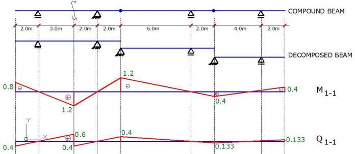
The figure below shows the influence line for internal stresses at section 1-1 when the load travels through the compound beam.
Interact with the structville community on facebook for more knowledge and information at www.facebook.com/structville


• I’m really enjoying the design and layout of your website. It’s a very easy on the eyes which makes it much more enjoyable for me to come here and visit more often. Did you hire out a developer to create your theme? Exceptional work! Documentation Services in India
ANIMATION SERVICES in India
CAD to BIM conversion in India
Reverse Engineering in India
So nice site, so much to learn, or at least to find a information. So long I plan to do it something like this on my native anguage….. I like this site so much