Overhead steel tank is one of the most adopted water storage system due to lots of reasons. The speed and ease of construction, flexibility in supporting different types of storage facilities, and diverse options are some of the most profound reasons. Furthermore, it can be easily dismantled and removed unlike their concrete counterpart that will offer more difficulties if it were to be removed at a later time.
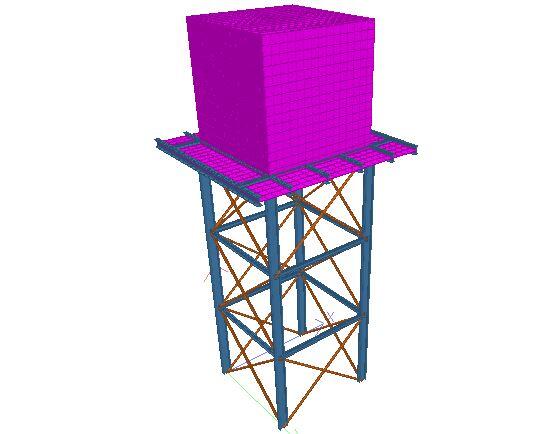
This post succinctly explains the process of carrying out the analysis of overhead tank using the popular Staadpro software. The tank to be modelled is as shown below. The stanchions are braced at intervals of 2.5m, and forms a square profile of 3m x 3m in plan. There are two primary beams sitting directly on top of the stanchions, and six secondary beams sitting on the primary beams. The secondary beams receive the tank directly, and are spaced at distance of 1m centre to centre at the middle span. The cantilever area has 0.8m projection (see image below). Note that this arrangement is just to briefly show modelling steps. I am convinced this structural arrangement could be made better especially when you look at the final result. That is what structural engineering is all about, you can treat this as a preliminary analysis that has been carried out, prior to final and more refined modelling, analysis and design.
Step 1: Create your nodes to form the base and the location of the stanchion.
To make this step easier, change your view to plan view. To switch to plan view, click on the icon circled in red at the top left corner of the screenshot below. Make sure that your UCS icon is as shown in the bottom left corner of the screen shot. You can create the first node, and use the copy and paste command to create the other nodes.
Step 2: Create other nodes to capture the exact geometry of the frame
Using the ‘copy and paste’ command can make this step very fast for you. The ‘translational repeat’ command can also be used. For instance to create the next level using the copy and paste command, you can highlight the entire nodes, right click, select the copy command, and paste in the positive Y direction.
Step 3: Connect the nodes to represent the form of the structure
You can use the ‘connect geometry’ command (go to geometry, and select ‘connect along’) but note that the members to be connected must be selected or highlighted. Alternatively, you can use the ‘add beam’ command.
Step 4: Assign the member properties
The properties that we are going to assign is as follows;
Stanchions – UB 254 x 102 x 25
Tie beams – UB 127 x 76 x 13
Top beams – UB 203 x 102 x 23
Bracings – UA 50 x 50 x 6
(Note that for practical purposes, it is very advisable to keep the variability of sections to a minimum).
To create properties, click on general, go to properties, and click on section database (circled on the screen shot below). Select the properties above, and click add.
Assign the properties to the designated members. Your rendered view should look as shown below;
Step 5: Model the steel tank
We want the frame shown above to carry a cube steel tank of dimension 3m. This can be achieved by using the mesh tool. We are going to use a steel plate of thickness 15mm to model the square tank. Just in case the steel frame is going to carry plastic tanks as usually obtainable in Nigeria, you can model the floor plate only, and apply pressure load on the plate to represent the weight of the tank and water.
As you can see, the storage tank has been modelled. You can notice from the 3D rendering above that the centroid of the plates coincide with the centroid of the main beams. We can model it to look as realistic as possible by offsetting the beams such the plates will rest on the beams (the way it appears in construction). However, the only difference is that Staad will see this as a form of geometric imperfection, and high magnitude of unrealistic axial forces will be induced in the beams. But for all design and practical purposes, leaving it this way is very okay, and gives a representation of the loads transferred so that appropriate sections can be selected.
However, we know that the primary beams are not receiving the loads from the tank directly. The load from the tank goes first to the secondary beams, which now transfer the loads to the primary beams, and to the stanchions. You can achieve this by merging the primary beams where necessary.
Step 6: Support
Assign pinned support to the structure. This shouldn’t be challenging to you at all.
Step 7: Loading
The height of the main storage tank is 3m, but the maximum water level is 2.8m before it is discharged through a spill way.
The loading of the structure is as given below;
(1) Hydrostatic pressure on the walls of the tank (trianular load of 28 kN/m2)
(2) Full pressure load of 28 kN/m2 on the bottom of the tank
(3) Dynamic wind pressure of 2.5 kN/m2 acting on one side of the tank
(4) A live load of 1.5 kN/m2 acting on the exterior perimeter of the tank (maintenance area)
(4) Self weight of structural members.
We will treat the weight of water as dead load in this case, since we know the maximum level it can get to.
Step 8: Analysis and results
When the structure is analysed, the following results are obtained;
Stanchions:
Maximum Axial loads:
Dead load – 82.2 kN (compression)
Live load – 4.39 kN (compression)
Wind load – 36.3 kN (compression) and 36.3 kN (tension)
Maximum bending moment
Dead load – 0.73 kNm
Live Load – 0.33 kNm
Wind Load – 4.21 kNm
Main beams
Bending Moment
Dead load = 28.6 kNm
Live load = 0.913 kN
A sample bending moment of the structure is as given in the image below;
The deflected profile of the structure due to wind load is given below;
After such analysis, you can take your time to view the results of your model. This was just to show some salient approaches that can be used to model overhead tank. I will keep improving on the post terms of delineating the steps, and reporting the results as appropriate as time goes bye……
Your reactions are highly welcome.
See you later……..


good Job, but your post didn't give details of connections, either bolts or welding and specifications.
The post was for internal forces only… Just analysis and not design
great Job Ranks
Thank you very much
After meshing the plates used to model the tank, how can I get to easily group select the plates (eg the walls of the tanks)? The meshed walls are now in smaller sections.
The meshed walls are expected to be broken (finite element analysis).
Great work!!! Can this be done in Etabs?
Great work engineer. Am really excited reading your blog. It will be very helpful if u will kindly show us hw to use dis internal stresses to design dis overhead tank. Thank u very much again.
Hi, what do you mean with “ You can achieve this by merging the primary beams where necessary.“ ?, does it need to merge the primary members first before run analysis?, does it have any effect or need specification to assign?, thanks
Great work sir, God bless you more.
Please Sir, how do you come about the loads of the tank, i mean the calculation procedure.
Thank you Sir
great job,
ramers are autonomous, invest heavily in their exchange and love to work and play outside a genuine red-blooded people. Commercial interior Contractors Vancouver
Thanks for the detailed information. Good Work.
Great job
though the post is from way back before, but is been so helpfully in most of our project done.
Good job Engineer, just saw this of recent. Could you show how these load cases in Orion and how they were applied. moreso if the tank were plastic how would the load be applied plate and secondary beams?