In our last post, I highlighted the different methods of loading sub-frames such as to obtain the maximum design moment on the columns (Follow the link below to see it). In this post, I am going to show with a practical solved example how to analyse sub-frames for obtaining the maximum moment.
Read….
How to Load R.C. Columns for Maximum Design Moment
We are going to use the general arrangement given below as a case study.
We have already analysed the load on this building. Just in case you missed it follow the link below;
Read
Analysis of Columns Loads in A Building By Considering Beam Support Reactions
We are going to pick column A1 as a case study, to obtain the design moment in the z direction. Due to the location of this column (corner column), we are going to consider one span (Beam A:1-2) only fully loaded at ultimate limit state 1.35gk + 1.5qk.
In our previous post following the link above, this has been determined as 41.752 kN/m .
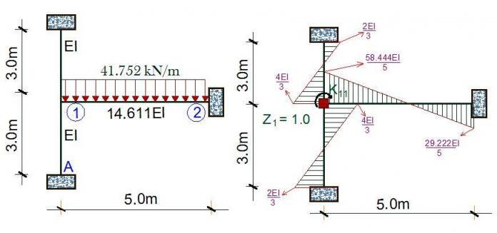
Therefore, the loading is as shown below;
We know that the preliminary dimensions of the columns are 230 x 230mm, while the beams are 230 x 450mm. However, we know that the beams are technically not rectangular sections (they are L- beams) by virtue of their location. Therefore, we have a little job of calculating the beams flange width, and moment of inertia. Note that at this stage, we do not consider the effect of reinforcement in determining the moment of inertia, and the main aim of this process is to determine the value of k in the picture above so that our calculation will be as accurate as possible.
For an L-beam, the flange width is as given below;
Beff = 0.2(5770/2) + 0.1 (0.85 × 50000 + 230 = 1232mm
To learn how to calculate flange width, click here;
Therefore, the section is as shown below;
We can use our knowledge of statics to find the moment of inertia of the shape above. I believe there are charts that can help us compute this faster based on the bw/beff and h/hf ratio or thereabout. But let us just go through this the old school way.
We can now calculate the moment of inertia using the parallel axis theorem;
For rectangle 1;
IG = bh3/12 = (1232 × 1503)/12 = 346500000 mm4
y = 375 – 313.829 = 61.171 mm
Ixx1 = IG + Ay2
Ixx1 = 346500000 + (184800 × 61.1712) = 1.038 × 109 mm4
For rectangle 2;
IG = bh3/12 = (230 × 3003)/12 = 517500000 mm4
y = 313.829 – 150 = 163.829 mm
Ixx2 = IG + Ay2
Ixx2 = 517500000 + (69000 × 163.8292) = 2.3694 × 109 mm4
Therefore, IB = Ixx1 + Ixx2
IB = (1.038 × 10⁹) + (2.3694 × 10⁹) = 3.4074 × 109 mm4
We have now gotten the moment of inertia for the beam
We can quickly verify that for the columns, the moment of inertia can be obtained by;
IC = bh3/12 = (230 × 2303)/12 = 2.332 × 108 mm4
Summarily, we can now say that;
k = IB/IC = (3.4074 × 10⁹)/(2.332 × 108) = 14.611
Having obtained our k, the diagram of the structure is as shown below. But because we are actually overestimating the stiffness of the structure by assuming all ends to be fixed, we have to reduce this value by half. Therefore k/2 = 7.3055
We are going to tackle this problem using the stiffness approach. Kinematically, the structure is indeterminate to the first order, being the rotation at node 1.
We are going to fix the node up, so as to restrain it from any form of rotation. This forms the basic system of the structure. Now, we will apply a unit rotation at the node, and the resulting bending moment on the basic system is as given below;
The appropriate cannonical equation is given by;
k11Z1 + k1P = 0
The bending moment at point 1 due to unit rotation at point 1 (k11) is given by;
k11 = (4EI/3) + (4EI/3) + (29.222EI/5) = 8.511
k1P = fixed end moment due to external load at that point = -ql2/12 = (-41.752 × 52)/12 = -86.983 kNm
8.511Z1 = 86.983
On solving;
Z1 = (10.22/EI) radians
Therefore the moment at the top of the column;
M1B = (10.22/EI) × (4EI/3) = 13.627 kNm
So by implication, the ground floor column A1 is subjected to a moment of 13.627 kNm in the z-direction at the top. Can you model this structure on Orion or Staad and see what your answer will be?
You can also follow the same procedure and obtain the design moment in the x-direction.
Just in case you are not very familiar with stiffness method of structural analysis, this post below will help.
Read…
Analysis of Sub-frames Using Stiffness Method
Thank you for visiting Structville today! See you next time.


• You really make it appear really easy together with your presentation but I to find this topic to be actually something that I believe I’d by no means understand. It sort of feels too complicated and extremely extensive for me. I am taking a look forward in your subsequent submit, I will try to get the hang of it!.
Reverse Engineering in India
Point Cloud to BIM conversion in US
Energy Analysis in India
Structural Analysis in India
Shop Drawings Preparation in India
very great job on your blog. and please do visit the link below
Energy Analysis in India
Pretty good post. I just stumbled upon your blog and wanted to say that I have really enjoyed reading your blog posts. Any way I'll be subscribing to your feed and I hope you post again soon. Big thanks for the useful info. Freezer repair Calabasas