Fixed offshore platforms are used by the petroleum industry for a variety of operations, including drilling, production, housing, and storage. These constructions are situated offshore but closer to the coast than regular offshore platforms as a result of the recent growth in demand for LNG terminals. With regard to loading and foundation design, LNG terminals and offshore platforms are very similar, and the majority of what is covered here also applies to LNG terminals.
Steel constructions that are supported by piles or suction foundations or gravity platforms (GBS = “Gravity Based Structure”) that rest on the ocean floor can be used for permanent, fixed offshore platforms. Typically, open-ended tubular piles are driven for this purpose. Instead of driven piles, a few steel platforms are supported by steel suction caissons. The gravity platforms are made of steel or concrete and have skirts that reach the seafloor.
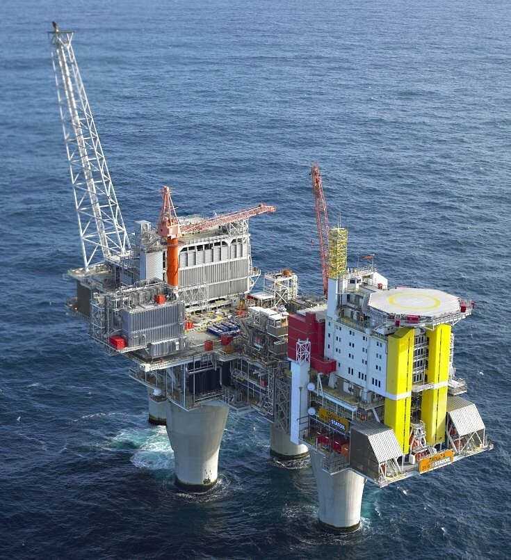
The Ekofisk Oil Storage Tank, which is situated in approximately 60 meters of water, has short skirts that only penetrate about 0.6 meters into extremely dense sand, in contrast to the tallest GBS to date, which is located in the Troll field in the North Sea in about 330 meters of water. All of this serves to illustrate how important a site’s geotechnical properties are to the design of any structure.
Offshore platforms frequently have large deck loads and, in exposed places, will be subject to powerful storm loads. High dynamic loads are imposed by earthquakes in seismic regions, which may weaken the soil. Because of the loads that the foundation must support, foundation engineering is an important step in the design process.
Jack-up platforms can only be used in shallow waters, are often only installed for a short time (months rather than years), and are usually supported by spudcans.
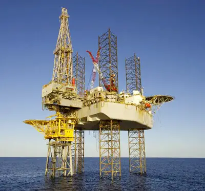
The installation of various kinds of big floating structures is one of the most recent technologies for oil and gas exploration in the deep sea. These floating structures must be properly anchored.
Most offshore oil and gas fields have a small number of buildings. This is in contrast to an offshore wind farm, which is made up of numerous independently created wind turbines placed throughout the wind farm region. Suction caissons, monopiles, jacket piles, tripods, and gravity-type foundations are available for wind energy towers.
Foundation Design Issues for Offshore Platforms
For offshore platforms, some significant foundation design concerns include:
Bearing Capacity
Regardless of the structure, the subsoil needs to be able to support the static and cyclic loads with a safe enough margin against excessive displacements or failure. Potentially distinct from the bearing capacity under monotonic loading is the capacity under cyclic loading. Design considerations such as the soil’s bearing capacity under cyclic loads are also very important.
The parameters required for the evaluation of the bearing capacity are;
− Monotonic shear strengths under different stress paths
− Cyclic shear strength under combined average and cyclic shear stresses for triaxial and simple shear stress paths.
− Undrained angle of shearing resistance (sand).
Permanent Displacement (e.g. settlement)
Static actions will result in initial settlements as well as settlements in the soil outside and beneath the platform as a result of consolidation and creep. Due to increasing shear stresses and the dissipation of cyclically produced pore pressure, the cyclic loading from waves and/or earthquakes will result in extra permanent displacements.
The permanent displacements will decrease the freeboard—the distance between the deck of the platform and the water’s surface—and may put mechanical connections to things like oil wells, risers, and pipelines attached to the platform under stress.
The parameters required for the evaluation of the permanent displacement are;
− Compressibility
− Permeability
− Permanent shear strain and pore pressure under combined average and cyclic shear stresses for triaxial and simple shear stress paths
− Compressibility after cyclic loading
Cyclic displacements
The soil and the platform are displaced cyclically as a result of cyclic loads. Cyclic displacements of the platform could make it difficult for the people and equipment on the platform to function optimally. Cyclical displacements, like permanent displacements, can lead to stresses in the structural components and any connections to the structure.
The parameters required for the evaluation of the cyclic displacements are;
− Cyclic shear strain as a function of cyclic shear stress under combined average and cyclic shear stresses for triaxial and simple shear stress paths.
− Initial shear modulus.
Foundation Stiffness
For structural dynamic assessments under wave and/or earthquake loads, equivalent soil spring stiffness data are required. For platforms in deep water, the resonance period may be close to the period of the wave load, resulting in a large amplification of the wave load. Therefore, it’s crucial to either calculate and design for the wave load amplification factor or make sure the resonance period is sufficiently far from the wave load period.
The parameters required for the evaluation of the foundation stiffness are;
− Cyclic shear strain as a function of cyclic shear stress under combined average and cyclic shear stresses for triaxial and simple shear stress paths
− Initial shear modulus
− Damping
Reaction stresses in the soil
GBS constructions need to be built to withstand the stresses that the soil will experience from both static and cyclic loads. The soil reaction stresses may be particularly severe in some areas of an uneven seabed that is made up primarily of dense sand. Due to creep and the cyclical erosion of the soil modulus, the soil response stresses may also redistribute over time.
The parameters required for the evaluation of the reaction stresses are;
− Monotonic and cyclic shear strengths.
− Compressibility under virgin loading and reloading.
− Cyclic and permanent shear strains and permanent pore pressure under combined average and cyclic shear stresses for triaxial and simple shear stress paths.
− Seabed topography, objects on the seafloor.
Skirt penetration
To ensure that GBSs with skirts will reach the intended penetration depth, the skirt penetration resistance must be computed.
The parameters required for the evaluation of the skirt penetration are;
− Undrained anisotropic monotonic shear strengths.
− Remoulded shear strength (or sensitivity).
− Drained angle of shearing resistance (sand).
− Residual interface angle of shearing resistance (sand).
− CPT resistance (sand).
− Seabed topography and objects on the seafloor.
− Boulders in the soil within the skirt penetration depth.
Pile driveability
The selection of pile driving equipment must be carefully considered in order to guarantee that the pile can withstand the driving stresses and that an acceptable penetration depth is achieved.
The parameters required are;
− Axial and lateral response.
− Shear strength.
− Soil modulus or strain at 50% ultimate strength
− CPT cone resistance
Punch-through
The legs of a jack-up rig are often preloaded with ballast water before the footings (spudcans) are placed. Due to the rising ballast burden, these will pierce the seabed. In soils with a limited increase in soil strength with depth and in soils where a strong layer of limited thickness lays on top of a weaker layer, rapid, uncontrolled penetration may happen.
Analyses of liquefaction potential
This is necessary for locations with sands or silty sands, as well as seismically active regions and areas with the potential for high wave loading.
Liquefaction potential can be assessed using the following parameters;
− Initial shear modulus
− Cyclic shear modulus degradation curves
− Damping
− Coefficient of reconsolidation (sand)
Erosion and scour
Around offshore sites, erosion and scour may be brought on by waves and currents. In comparison to clay, sand has a higher propensity for scouring, which normally rises as water depth falls. A graded gravel fill may be necessary around the perimeter of gravity platforms constructed on sand in order to prevent erosion. Skirts around the edge will assist stop the base from scouring. Scour can be accommodated in the case of piles by including a specific scour depth in the design.
Permeability tests can be used to assess erosion and scour potential.
Soil and Rock Parameters Required
To address these design issues highlighted for offshore platforms, geotechnical and geological information needs to be collected. The sections below list the basic and specific soil and rock parameters needed for a typical offshore platform’s foundation design.
Clays
− General description
− Layering
− Grain size distribution
− Water content
− Total unit weight
− Atterberg (plastic and liquid) limits
− Indicative shear strength (miniature vane, torvane, pocket penetrometer, fall cone, UU, etc.)
− Remoulded shear strength
− Sensitivity
− Soil stress history and overconsolidation ratio
− Organic material content
Sand, silt, or gravel
− General description
− Layering
− Grain size distribution
− Water content (silt)
− Maximum and minimum densities
− Relative density
− Drained angle of shearing resistance
− Soil stress history and overconsolidation ratio
− Angularity
− Carbonate content
− Organic material content
Rock
− General description
− Rock Quality Designation (RQD)
− Water absorption
− Total unit weight
− The unit weight of solid blocks
− Unconfined compression strength
− Mineralogy
− Carbonate content
Typical Scope of Geophysical Investigations
The following are the typical scope of work for the geophysical investigation.
Seabed Topography
Minimum survey area: Usually 1 km x 1 km in shallow water, 2 km x 2 km in deep water. Possible extension to 5 km x 5 km in areas with geohazards to incorporate possible platform location shifts etc.
Means of survey: Swath bathymetry, preferably multibeam
Seabed features
Minimum survey area: Usually 1 km x 1 km in shallow water, 2 km x 2 km in deep water. Possible extension to 5 km x 5 km in areas with geohazards to incorporate possible platform location shifts etc.
Means of survey: Sidescan sonar, line spacing 100-200 m depending on water depth, with sonar range set to provide 200 % coverage from line overlap.
Subsurface Information
Minimum survey area: Usually 1 km x 1 km in shallow water, 2 km x 2 km in deep water. Possible extension to 5 km x 5 km in areas with geohazards to incorporate possible platform location shifts etc.
Means of survey: High-resolution / ultra high-resolution seismic survey for shallow geology and fault offset analysis. Line spacing: 100 m to 200 m depending on water depth. May be performed simultaneously with sidescan sonar. Also, 3D exploration seismic data (where available) to approximately 1.5 milliseconds for regional geohazard analysis and drilling hazard analysis to approximately 1000 m depth.
Typical Scope of Geotechnical Investigation
Gravity Platforms
The typical scope of work for the geotechnical survey of a gravity platform includes the following;
(1) 1 no. BH with continuous sampling down to 15 m, thereafter sampling with less than 0.5 m gaps to 0.5 – 0.7 times the platform diameter, followed by alternate sampling and CPT (preferably (P)CPT) with less than 0.5 m gaps. The minimum depth of penetration should be 1.5 times the platform diameter.
(2) 3 nos. BHs with continuous sampling to 15 m, thereafter sampling with less than 0.5 m gaps. The minimum depth of penetration should be 50 m.
(3) 10 nos. continuous (P)CPTs. The minimum depth of penetration should be 50 m or 1.5 times the platform diameter.
Sample testing
The samples retrieved from the subsurface exploration should be subjected to the following engineering tests;
- Index testing,
- Triaxial tests
- Oedometer tests.
- Permeability tests.
- Simple shear tests and anisotropically consolidated compression and extension triaxial tests, monotonic and cyclic.
- Shear wave velocity measurements by bender elements to determine initial shear modulus.
- Resonant column tests.
- X-ray photographs to determine soil layering within the tube, inclusions, sample quality.
- Radioactive core logging (optional).
Piled Platform
The typical scope of work for the geotechnical survey of a piled offshore platform includes the following;
(1) 1 no. BH with samples every metre down to 15 m, thereafter sampling with less than 0.5 m gaps to 30 m, followed by alternate sampling and CPT (preferably (P)CPT) with less than 0.5 m gaps or 2 nos. BHs: one with sampling only and one with near-continuous CPT. The minimum penetration should be 4 pile diameters or pile penetration plus pile group, diameter, whichever is greater.
(2) Continuous (P)CPTs at a location 5-10 m from the main borehole. The penetration depth should be 30m.
Sample Testing
- Index testing,
- Testing for pile capacity and drivability, and for (static mudmat) bearing capacity
Jack-up Rig Platform
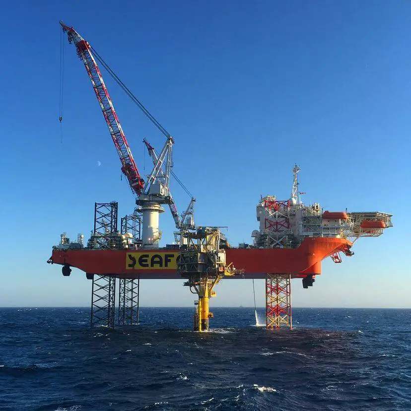
The typical scope of work for the geotechnical survey of a jack-up offshore platform includes the following;
(1) 1 no. BH with samples at every metre down to 15 m, and thereafter gaps less than 0.5 m. The minimum depth of penetration should be 30 m or anticipated spudcan penetration + 1.5 times spudcan diameter, whichever is deeper.
(2) 1 no. Continuous (P)CPT at a location 5 to 10 m from the main borehole and/or at each leg location. The minimum depth of penetration should be 20 m.
Sample Testing
- Index testing
- Testing for static bearing capacity
The scopes of work listed above are representative of common platforms and uniform soil types. The size of the platform and the soil’s heterogeneity over the platform’s footprint determine how many boreholes are needed. Additionally, one should account for potential adjustments to the footprint’s size or precise placement.
Once the design is underway, it’s also feasible that the platform’s type will be changed. The intended use of the proposed platform and the implications of risk analysis for potential subpar performance of the structure or the soil also influence the number of test sites.
The number of borings, (P)CPTs, and other in-situ tests are also based on the site’s ground variability as identified by preliminary geophysical investigations. Additional borings or (P)CPTs are especially required close to geophysical anomalies or close to discontinuities in the layers of the soil or rock.
Therefore, depending on size and soil variability, a GBS may require one or two deep boreholes in addition to shallow boreholes/CPTs. For a larger structure, more shallow boreholes are likely to be required. Depending on the size and soil variability, between one and four deep boreholes may be needed for piled construction.
For the measurement of horizontal soil resistance on piles and the design of mudmats, further CPTs or sample borings may be necessary. For axial pile design at sand sites utilizing existing CPT-based design approaches, near-continuous CPT profiles are necessary. It has been recognized that deeper penetration of piles leads to an increase in the axial capacity for piles, hence it’s important to characterize these deeper soils properly. For instance, one wouldn’t want to overlook clay bands, at the intended point elevation in a deep sand.
Conclusion
Site investigations for offshore platforms should ideally be carried out in stages. The number of in-situ testing may be limited in the early stages of a project to the data required to assess the viability of various construction forms. In this case, extra testing will be needed before moving on to the detailed design step.
The chance that the platform location will change due to changes in the field layout, the platform’s qualities, and the mooring leg properties should be taken into account throughout the site investigation. A more trustworthy evaluation of in-situ strength and stiffness parameters would include penetration tests (cone, T-bar, or ball), vane shear tests, and pressuremeter testing in addition to sample borings.




I’m very much interested in getechinical investigation assignment