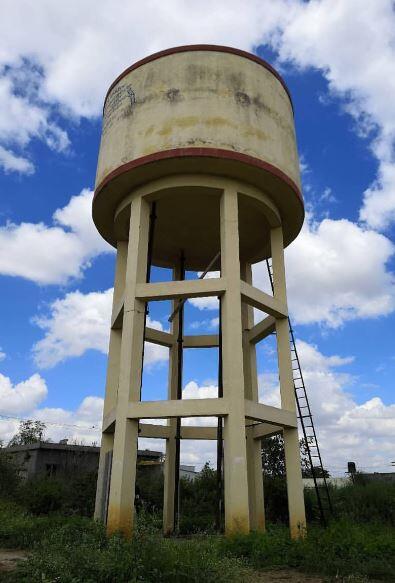
Water tanks are usually rectangular or cylindrical in shape. Cylindrical tanks are normally used for surface or elevated water tanks, while rectangular tanks can be used for underground, surface, or elevated water tank construction. The aim of this article is to compare the analysis of cylindrical water tanks subjected to hydrostatic load using the classical method and finite element analysis.
Some researchers have tried to compare the structural performance of cylindrical and rectangular water tanks under the same conditions such as volume, height above the ground, or aspect ratio. A study carried out in the year 2017 showed that circular water tanks require lesser materials than rectangular water tanks. However, some of the challenges in the construction of cylindrical tanks are increased cost of setting out, formwork preparation/installation, reinforcement installation, and general increased labour cost when compared with a rectangular tank.
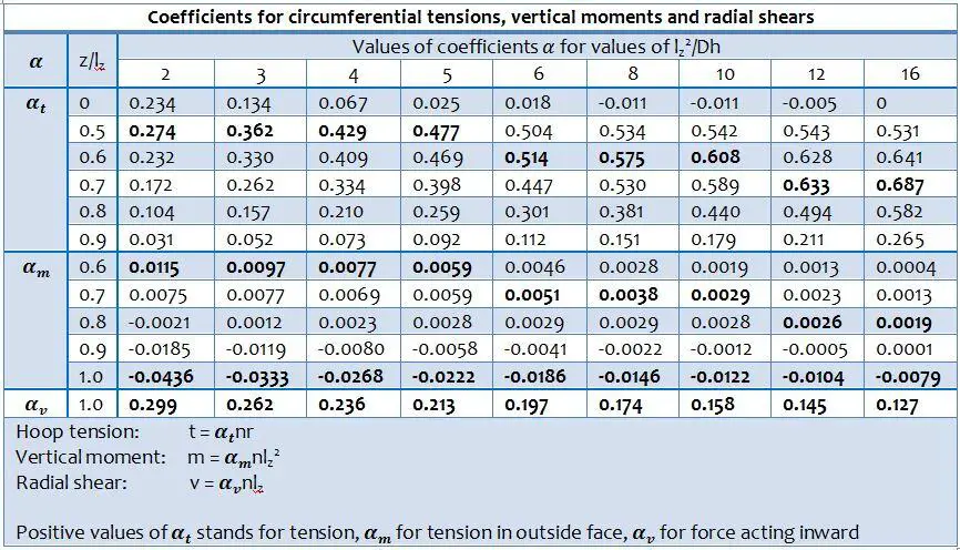
Cylindrical tanks are subjected to radial pressure from the stored water, and/or from the retained earth when they are buried under the ground. Just like rectangular water tanks, the analysis of cylindrical water tanks can be easily done with the use of coefficients picked from tables (see Table 1). The values of the coefficients are usually based on the support condition of the wall relative to the base.
The internal stresses normally analysed for in circular tanks are;
- Circumferential tension (hoop tension)
- Radial shears
- Vertical moments
If the walls of the tank are supported on the base in such a way that no radial movement can occur, radial shear and vertical bending result, and the circumferential tension are zero at the bottom of the wall. This is usually referred to as the fixed joint condition and has been considered in this article.
Analysis of Cylindrical Water Tanks – Worked Example
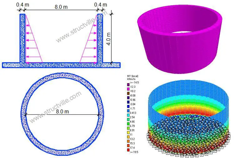
Determine the maximum service values for circumferential (hoop) tension, vertical moment and radial shear in the wall of a cylindrical tank that is free at the top edge and fixed at the bottom. The wall is 400 mm thick, the tank is 4 m deep, the diameter is 8 m, and the water level is taken to the top of the wall.
Hydrostatic pressure at the base of the tank (n) = 10 kN/m3 × 4 m = 40 kN/m2
From Table 1;
lz2/Dh = 42/(8 × 0.4) = 5
Maximum hoop tension (t) = αtnr = 0.477 × 40 × 4 = 76.32 kN/m
Table 1: Coefficients for Analysis of Cylindrical Tanks Fixed at the Base (Reynolds and Steedman, 2008)
Maximum vertical negative moment (outside face) = αmnlz2 = 0.0059 × 40 × 42 = 3.776 kNm/m
Maximum vertical positive moment (inside face) = αmnlz2 = 0.0222 × 40 × 42 = 14.208 kNm/m
Radial shear V = αvnlz = 0.213 × 40 × 4 = 34.08 kN/m
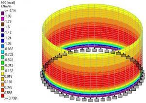
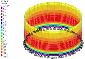
When analysed on Staad Pro as a concrete cylindrical tank with a Poisson ratio of 0.2, fixed at the bottom, and subjected to a hydrostatic pressure of 40 kN/m2 the following results were obtained;
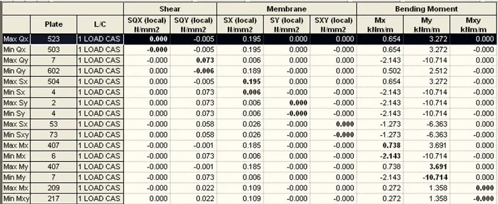
The summary of the finite element analysis results from Staad Pro is shown in Table .
Table 2: Summary of the finite element analysis results from Staad Pro
Maximum vertical bending moment = 10.714 kNm/m
Maximum vertical shear stress = 0.073 N/mm2 = 29.2 kN/m
Maximum hoop stress (membrane) = 0.195 N/mm2 = 78 kN/m
Let us compare the results from Staad Pro with results from the use of coefficients (see Table 3).
Table 3: Comparison of analysis result using classical method and finite element analysis

Thank you for visiting Structville today and God bless you. If you have some time, you take a look at our QUIZ and evaluate your performance.





Thank you very much!
I high appreciate this post. It’s hard to find the good from the bad sometimes, but I think you’ve nailed it!
Good day, pls why is the self weight of this structure not considered in the design?
Thank you sir