In the design of a pile foundation, the geotechnical engineer is expected to hand over the soil investigation report to the structural engineer, who will proceed to provide the longitudinal reinforcements needed for the piles and also design the pile cap. The structural design of a pile cap is an important aspect of pile foundation design and the method of carrying out the design has been presented in this article.
The soil investigation report handed to the structural engineer for the design of pile foundation purpose should contain the embedment length of the piles, the recommended sizes of the pile, the safe working load of each pile size, and other information that may be necessary for the structural engineer to do his design properly. All aggressive materials in the soil should be stated as well so that adequate protection will be given to the pile material(s) for durability.
The first step in the structural design of a pile cap usually involves obtaining the number of piles required to support each column load. This is usually done using the service loads of the column, and relating them to the safe working load of the piles from the soil investigation report. In this article, we are going to show how the structural design of reinforced concrete pile foundations and pile caps can be done based on practical design and site experience.
Design Example
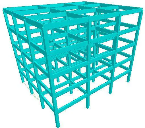
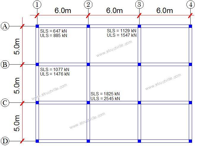
The frame of a 5 storey building is shown in Figure 1, and it is expected to be supported on piles with an embedment length of 20 m. The allowable working loads of the bored pile (CFA) is shown in Table 1. fy = 460 Mpa, fcu = 30 Mpa
Table 1: Pile safe working load
| Pile diameter (mm) | 300 | 450 | 600 | 750 | 900 |
| Safe working load (kN) | 246.74 | 370.11 | 493.48 | 616.85 | 740.22 |
Design for Column A1
Service axial load on column = 647 kN
Ultimate axial load on column = 885 kN
Size of column = 450 x 230 mm
Try 2 No of piles
Service load per pile = 647/2 = 323.5 kN
Let us adopt 600 mm diameter piles for uniformity and to have fewer pile boring points
Safe working load of φ600 mm piles = 493.48 kN > 323.5 kN Okay
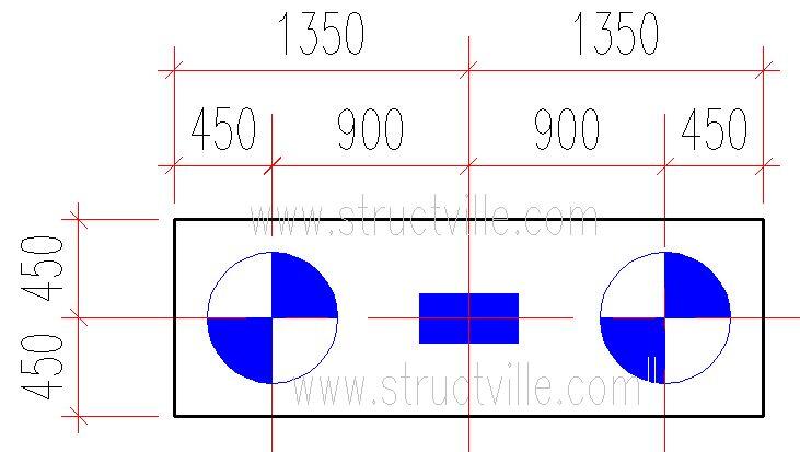
Centre to centre spacing of piles = 3φ = 3 x 600 = 1800 mm
Overhang of pile cap edge from the pile = 150 mm
Total length of pile cap = 1800 + 600 + 2(150) = 2700 mm
Width of pile cap = 600 + 150 + 150 = 900 mm
Thickness of pile cap = 2φ + 100 = 2(600) + 100 = 1300 mm
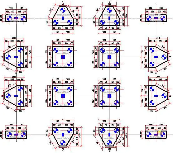
The layout of the pile cap is therefore given as shown in Figure 3.
Let us quickly carry out the structural design of pile cap Type 1 according to BS 8110-1:1997. You can also read Design of Pile Cap According to Eurocode 2.
From Table 3.61 of Reynolds et al. (2008), the tensile force to be resisted within the pile cap is given by;
Ft = N/(12ld)[3l2 – a2]
Where;
N = Column axial load at ultimate limit state
l = Centre to centre spacing of the piles
d = Effective depth of the pile cap
a = dimension of the column side parallel to the length of the pile cap
Self weight of the pile cap (ULS) = 1.4 x Area x depth x 24 kN/m3 = 1.4 x 2.7m x 0.9m x 1.3m x 24 kN/m3 = 106.14 kN
N = 885 kN + 106.14 = 991.142 kN
l = 1.8 m
d = 1300 – 100 = 1200 mm = 1.2 m
a = 0.45 m
Ft = [991.142/(12 x 1.8 x 1.2)] x [3 x 1.82 – 0.452] = 364 kN
Ast = Ft/0.95fy = (364 x 1000)/(0.95 x 460) = 833 mm2
Asmin = 0.13bh/100 = 1690 mm2
Provide 6T20 @ 175 c/c (Asprov = 1974 mm2)
Check for shear
Critical position for shear on vertical section across full width of pile-cap occurs at distance from face of column given by:
av = 0.5(l – c) – 0.3φ = 0.5(1800 – 450) – (0.3 x 600) = 495 mm
The shear force carried by the piles V = 991.142/2 = 495.571 kN
The shear stress ν = V/bd = (495.571 x 1000)/(900 x 1200) = 0.458 MPa
Concrete resistance shear stress vc = 0.632(100As/bd)1/3(400/d)1/4
vc = 0.632 x [(100 x 1974)/(900 x 1200)]1/3 x (400/1200)1/4 = 0.632 x 0.557 x 0.759 = 0.275 MPa
For grade 30 concrete, vc = 0.275 x (30/25)1/3 = 0.292 Mpa
vc(2d/av) = 0.292 x [(2 x 1200)/495] = 1.415 MPa > 0.458 MPa This is okay
Shear stress at column perimeter
ν = V/ud = (885 x 1000)/[(2 x 225 + 2 x 450) x 1200] = 0.546 MPa
This is less than 0.8√fcu = 4.38 Mpa. Therefore, this is okay.
Anti-burst bars of T12 @ 200 spacing should be provided
Main bars should be returned at least 900 mm into the sides to satisfy anchorage length requirements. You can take anchorage length to be conservatively 50 x diameter of reinforcement = 50 x 20 = 1000 mm
Design of Pile Cap Type 2
Service axial load on column = 1077 kN
Ultimate axial load on column = 1476 kN
Size of column = 450 x 225 mm
The number of φ600 mm piles required = 1077/493.48 = 2.184
Using 3 No of φ600 piles
Service load per pile = 1077/3 = 359 kN
Safe working load of φ600 mm piles = 493.48 kN > 359 kN This is okay
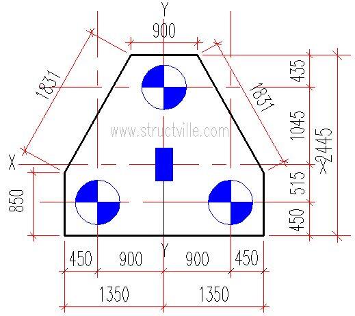
Let us adopt a triangular pile cap arranged in such a way that the column load will be equally distributed to the piles. This arrangement can be found in Table 3.16 of Reynolds et al (2008), and it is shown in Figure 4.
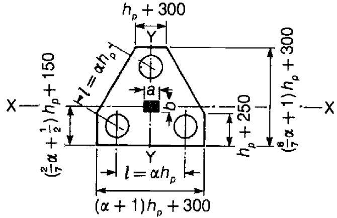
hp = φ = diameter of pile = 600 mm
Spacing of piles = 3φ = 3 x 600 = 1800 mm
Overhang of pile cap edge from the pile = 150 mm
(α + 1)φ + 300 = (3 + 1)600 + 300 = 2700 mm
φ + 250 = 600 + 250 = 850 mm
φ + 300 = 600 + 300 = 900 mm
(6α/7 + 1)φ + 300 = 2442.857 mm (say = 2445 mm)
(2α/7 + 0.5)φ + 150 = 964.285 mm (say = 965 mm)
Thickness of pile cap = 2φ + 100 = 2(600) + 100 = 1300 mm
The layout of the pile cap is shown in Figure 5.
Self weight of the pile cap (ULS) = 1.4 x Area x depth x 24 kN/m3 = 1.4 x 5.166 m2 x 1.3m x 24 kN/m3 = 225.61 kN
Total load on pile cap at ULS = 1476 kN + 225.61 kN = 1701.61 kN
l = 1.8 m
a = 0.225 m
b = 0.45 m
Tensile force to be resisted by the reinforcement in the direction parallel to X-X;
Ft,x = N/(36ld)[4l2 + b2 – 3a2]
Ft,x = [1701.61/(36 x 1.8 x 1.2)] x [4 x 1.82 + 0.452 – 3 x 0.2252] = 284 kN
Tensile force to be resisted by the reinforcement in the direction parallel to Y-Y;
Ft,y = N/(18ld)[2l2 – b2]
Ft,y = [1701.61/(18 x 1.8 x 1.2)] x [2 x 1.82 – 0.452] = 275 kN
Let us use the highest value for design in anticipation that we will provide the same reinforcement in both directions
Ast = Ft/0.95fy = (284 x 1000)/(0.95 x 460) = 649 mm2
Asmin = 0.13bh/100 = 1690 mm2
Provide T20 @ 175 c/c in both directions (Asprov = 1974 mm2)
Shear resistance
The shear force carried by the piles V = 1701.61/3 = 567.2 kN
The shear stress ν = V/bd = (567.2 x 1000)/(1000 x 1200) = 0.472 MPa
vc(2d/av) = 0.292 x [(2 x 1200)/495] = 1.415 MPa > 0.472 MPa This is okay
Shear will obviously not be a problem.
Design of Pile Cap Type 3
Service axial load on column = 1825 kN
Ultimate axial load on column = 2545 kN
Size of column = 400 x 400 mm
The number of φ600 mm piles required = 1825/493.48 = 3.69
Use 4 No of φ600 piles
Service load per pile = 1825/4 = 456.25 kN
Safe working load of φ600 mm piles = 493.48 kN > 456.25 kN This is okay
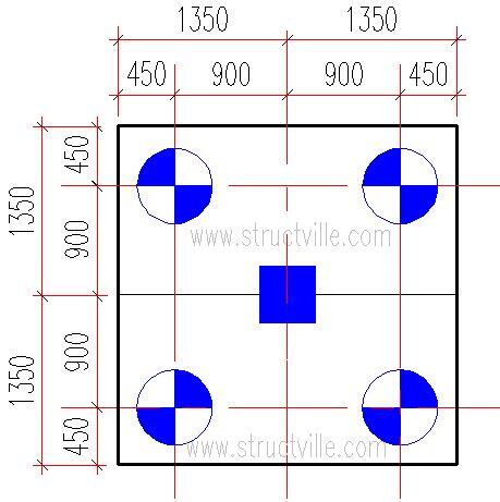
Let us adopt a square pile cap arranged in such a way that the column load will be equally distributed to the piles. This arrangement can be found in Table 3.16 of Reynolds et al (2008), and it is shown in Figure 6.
Self weight of the pile cap (ULS) = 1.4 x Area x depth x 24 kN/m3 = 1.4 x 7.29 m2 x 1.3m x 24 kN/m3 = 318.43 kN
Total load on pile cap at ULS = 2545 kN + 318.43 kN = 2863.43 kN
Tensile force to be resisted by the reinforcement in both directions;
Ft = N/(24ld)[3l2 – a2]
Ft = [2863.43/(24 x 1.8 x 1.2)] x [3 x 1.82 – 0.402] = 528 kN
Ast = Ft/0.95fy = (528 x 1000)/(0.95 x 460) = 1208 mm2
Asmin = 0.13bh/100 = 1690 mm2
Provide T20 @ 175 c/c in both directions (Asprov = 1974 mm2)
Shear resistance
The shear force carried by the piles V = 2863.43/4 = 715.9 kN
The shear stress ν = V/bd = (715.9 x 1000)/(1000 x 1200) = 0.595 MPa
vc(2d/av) = 0.292 x [(2 x 1200)/495] = 1.415 MPa > 0.472 MPa This is okay
The structural engineer is expected to provide the following drawings;
(1) Setting out drawing showing the piling points and layout with a known reference point
(2) General column/pile cap layout/arrangement
(3) Pile cap/ground beam/ground floor slab layout
(3) Columns, piles and pile cap reinforcement drawings (detailing)
(5) Ground beams and ground floor slab reinforcement detailing
(6) Construction procedure sketches
Construction Considerations
(1) Ground beams are usually provided to chain the pile caps together, and to provide the needed support for the ground floor slab. There are construction scenarios where the ground floor slab is placed directly on the pile caps, but note that this concept is quite different from piled raft foundation. The ground beams are usually embedded into the pile caps, or may be allowed to sit directly on the pile caps depending on the site level. A typical construction drawing showing this interaction is given in Figure 7.
(2) Contractor should maintain a minimum concrete cover of 75 mm
(3) There may be need to be cast the pile cap in two stages to achieve the configuration shown in Figure 7. The first casting will get to the bottom level of the ground beams (see Figure 8), then the ground beam reinforcements are laid (see Figure 9), before the final casting of the pile cap and ground beams to the required level (see Figure 10). Read about bonding of old and new concrete.

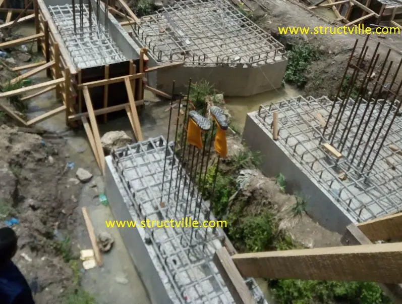
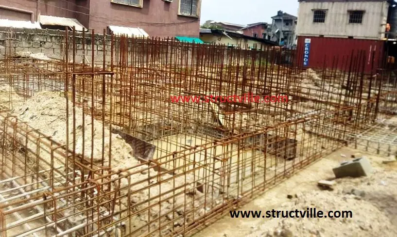
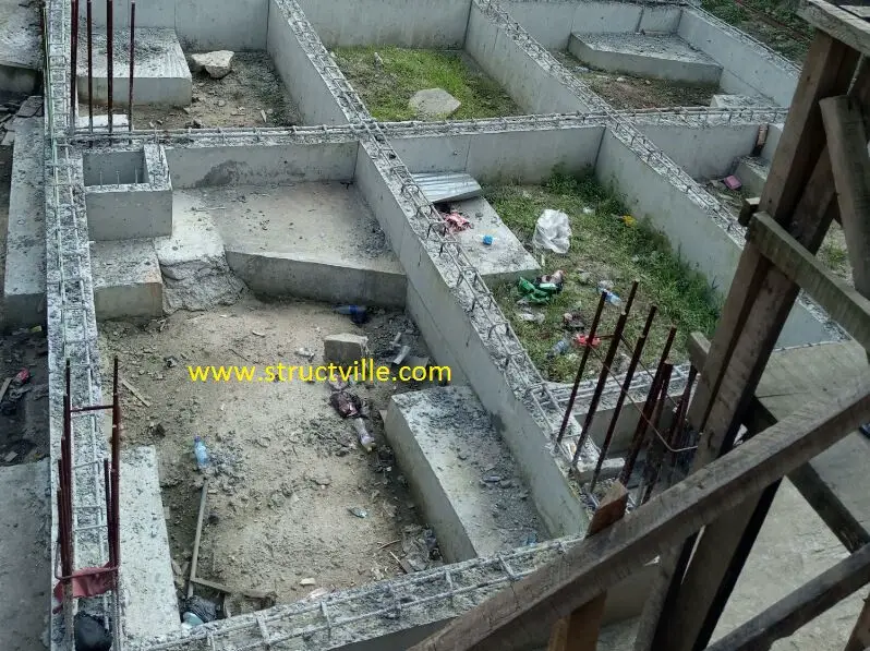
On getting to the stage shown in Figure 10, the bays are filled with sharp sand, and the ground floor slab is cast as appropriate.
Do you need help in design, consultancy, production of construction drawings, supervision, and project management, contact us today at Structville Integrated Services Limited. We are excellent at what we do, and we pride ourselves in professionalism and integrity. Send an e-mail now to info@structville.com copy structville@gmail.com or send a whatsapp message to +2347053638996.
References
[1] Reynolds C.E., Steedman J.C., Threlfall A.J. (2008): Reynolds’ Reinforced Concrete Designer’s Handbook 11th Edition. Taylor and Francis, New York




Dear Sir,
I was hoping to get a copy of this report/ design guide. It’s very nice. I am doing a research report for dynamic foundation on piles for my MS Degree and looking for good resources.
Thanks,
Jeff Leach
what is the allowable settlement limits for the piles. what about the effect group efficiency factor. How about modeling them on the FEM packages with Modulus of subgrade reaction & what will be value of modulus of subgrade reaction to be adopted in that case.
Allowable settlements can be computed using the recommended approaches. This is, however, a geotechnical thing. Pile group efficiency is also geotechnical thing and can be calculated using the famous Converse-Laborre formula. The settlement of piles should not exceed 10% of the pile diameter. All these can be checked when carrying out the pile load test, and incorporated into the safe working load of the pile.
I need this article engr
Good afternoon sir,
Hope youre having a splendid day? Please how do I download this article.
great
Very good job.
I was wondering if I could download it in a pdf format.
It would be very useful.
Can I have acces to this article sir Ubani
Excelente trabajo, gracias
Great well done Engr. Keep it up
Nice job sir.
What about the longitudinal reinforcement (size
and numbers) of the pile itself
Thanks
Find the link to that below;
https://structville.com/2018/06/provision-of-longitudinal-reinforcement-in-piles.html
Do we required the soil bearing capacity for the pile design as one of it’s parameters
This is just a wonderful basic explanation. Kudos to you
Any spread sheet ??
Is it necessary we reinforced the slab foundation or just mass concrete since the load is transferred through the column to the pile cap
It is usually reinforced. However, whether it is necessary depends on the assumptions made during the design.
Hi Ubani,
Would it be possible to have a copy of this design guide in PDF format. That would be very helpful!
Great job Engr Ubani, how do I relate this to a bridge construction?
I found this very instructive for quantity take off/measurement as a quantity surveyor. Helped me understand, in very simple terms, the connections between the ground beams and pile caps. Thanks a lot engineer Ubani.
Excellent Job =save life ??
In between two pile caps,is the ground beam start from natural ground level
On getting to the pile cap the ground beam vary in height?
Thanks
The height of the ground beam usually depends on the expected level of the ground floor slab. I have seen so many configurations. In some cases, the top of the beam flushes with the top of the pile cap, while in some cases it rises above the pile cap and receives the ground floor slab.
Fantastic breakdown of the relevant physics of the pile design process. You are no doubt a first-class engineer, cheers