Telecommunication masts or towers are tall structures that are designed for the transmission of telecommunication signals or for radio/television broadcasting. Telecom masts are usually made of steel structures of which the members can be made of hot rolled angle sections or circular hollow tube sections. Due to their height above the ground, the effect of wind is quite significant in the design of telecom masts and may govern the structural design.
Telecom masts can collapse for a variety of reasons of which wind can be one of them. According to Balczo et al (2006),
There are very few cases where masts collapsed, and the reasons for them are in most cases not the wind forces which were taken according to the standard into consideration at stress analyses, but coincidence of other fatal circumstances. … Out of 225 mast failures in Europe only 7 were caused by wind overload. It is also thought-provoking that the wind-storm in 1999 in Denmark caused no collapse of any masts although a number of masts should have been crashed according to the stress analyses carried out by using Eurocode.
Read Also…
Structural stability of a braced ten-storey steel frame
How to apply wind load on high-rise buildings
However, in Nigeria, a telecom mast was reported to have collapsed in Jalingo after a heavy storm in May 2018, which led to loss of lives. A similar incident was also reported in Edo State in the year 2018, after a heavy storm. However, no technical analysis was done to evaluate the cause of the collapse of the telecommunication masts.
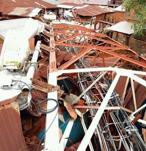
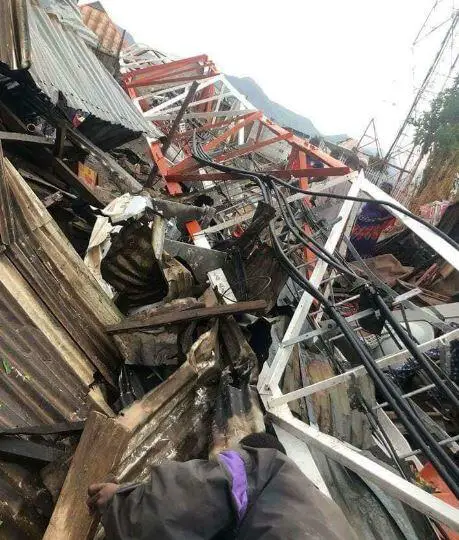
Different structural configurations can be adopted for telecom masts but it appears that the structural efficiency of all configurations is not the same. Therefore, this article aims to explore the effect of wind on different configurations of steel telecom masts.
In Europe, wind action on telecom mast can be evaluated according to the procedure described in EN 1991-1-4:2005 (Eurocode 1 Part 4) with emphasis on clause 7.11 of the code. In America, this can be evaluated according to the procedure described in ASCE-7 (2010).
In this article, the response of cross-bracing configuration (X-braced) and V-bracing structural configuration to wind load will be investigated using Staad Pro software and ASCE-7-2002.
The models used in the study are shown below.
Model 1: X-braced telecom masts
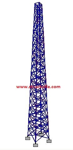
Type: X-Bracing
Height: 30 m
Width at the base: 3m x 3m
Width at the top: 1m x 1m
Section of the legs: UA 100 x 100 x 8
Section of the horizontal bracings and diagonals: UA 50 x 50 x 6
Design wind speed: 50 m/s
Building classification category: II
Exposure category: Category B
Solidity ratio: 20.6 %
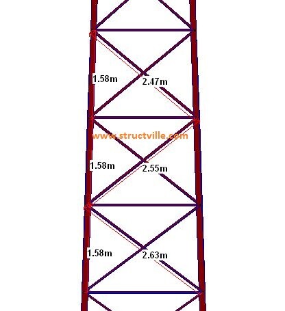
The following results were obtained when analysed for self-weight and the effect of wind load.
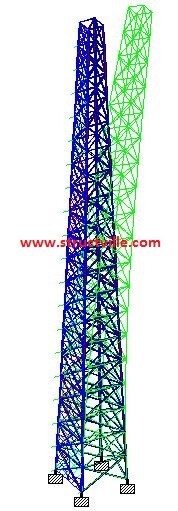
Maximum deflection at the top = 52.63 mm
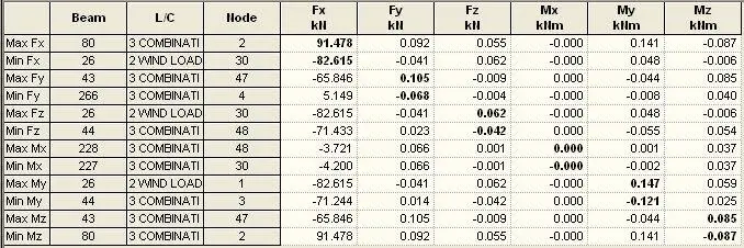
The maximum internal forces are shown below;
Model 2: V-braced telecom masts
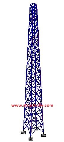
Type: V-Bracing
Height: 30 m
Width at the base: 3m x 3m
Width at the top: 1m x 1m
Section of the legs: UA 100 x 100 x 8
Section of the horizontal bracings and diagonals: UA 50 x 50 x 6
Design wind speed: 50 m/s
Building classification category: II
Exposure category: Category B
Solidity ratio: 19.51 %
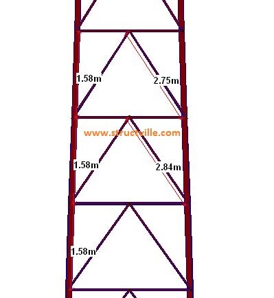
When analysed for the effect of wind, the result below was obtained;
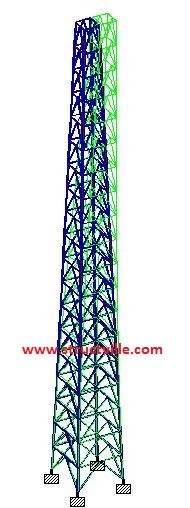
Maximum deflection at the top = 42.802 mm
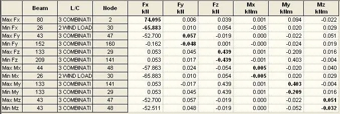
The maximum internal forces are shown below;
The table of comparison is shown below;
| Action Effect | X-Bracing | V-Bracing | % Difference |
| Deflection (mm) | 52.63 | 42.80 | 18.67% |
| Maximum axial tension (kN) | 82.615 | 65.883 | 20.25 % |
| Maximum axial compression (kN) | 91.478 | 74.095 | 19.00% |
From the table above, it can be seen that under the same conditions, V-braced masts perform better than X-braced masts under the effect of the wind.
When a lateral load is applied to an X-braced frame, the diagonal braces are subjected to compression while the horizontal web acts as the axial tension member in order to maintain the frame structure in equilibrium under lateral load. For V-braced frames (chevron bracing), one of the braces resists the tension while the other brace resists compression at each storey.
Both the tension and compression brace distribute the lateral load equally in the elastic range before the buckling point. However, the tension brace will remain in tension while the compression brace will lose all the axial load capacity after buckling. This contributes to the unbalanced distributed lateral load and can cause a large bending moment in the intersection of the beam and braces.
However, V-braced frames possess high elastic stiffness and strength when compared with X-braced frames.





Nice article and thanks for maintain Structville!. It is sad that the failure was not investigated, the steel members looks intact, I would guess anchors failed at tension?, or insufficient anchor length?, it would be nice a picture from the base of the mast.
About the model, I would check the drift at the “first level” within the chevron bracing model, it looks like “almost all” the deflection you got it at first level and the rest of the mast will have little drift as you reach the top. The X bracing model gives a cantilever-like deflection, as one can expect.
If you add a diamond in the center at all the levels, you’ll find displacement even lesser