When the most economical number of piles that will satisfy design requirements is three, a triangular-shaped pile cap can be adopted. In this case, the piles are arranged in a triangular manner, and equidistant from each other (usually spaced at 3 times the diameter of the pile).
Following the same arrangement, a similarly shaped pile cap can be used to transfer the loads to the piles. Triangular pile caps can be analysed and designed using the strut-and-tie method, beam analogy, or finite element analysis.
In our post on Structural Aspects of Pile Foundation Design, we showed how we can determine the number of piles required to support a column load, and we went ahead to design a triangular pile cap based on the strut-and-tie method (truss analogy).
In this article, we are going to analyse the same triangular pile cap using bending theory and finite element analysis and compare the results obtained.
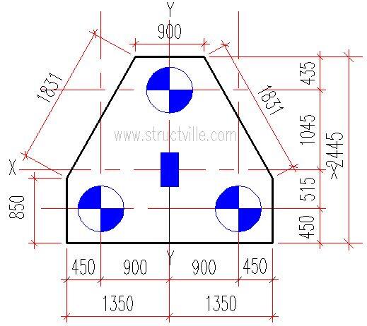
The layout of the pile cap is shown in Figure 1 and we are going to assume that it is subjected to an axial load of 2500 kN from a 300mm x 300mm column (neglecting the orientation of the column in Figure 1).
Bending Theory Analysis of Triangular Pile Cap
The load on each pile is computed based on its distance from the centroid of the column
Load on the single pile
N1 = N(Ay – Ay‘)/Ay
Where:
N = Axial load from column = 2500 kN
Ay = Vertical distance between the centriod of piles in the y-direction = 515 + 1045 = 1560 mm
Ay‘ = Vertical distance between the centroid of the column to the centroid of the single pile in the y-direction = 1045 mm
Hence N1 = 2500 x (1560 – 1045)/1560 = 825. 321 kN
Load on the twin piles
N2 = (N – N1 ) / 2
N2 = (2500 – 825.321)/2 = 837.3395 kN
Bending moment in the x-direction
Mx = N2 x (Ax – Cx)/2
Ax = Spacing of the twin piles = 1800 mm
Cx = Width of the column parallel to x-direction = 300 mm
Mx = 837.3395 x (1.8 – 0.3)/2 = 628 kNm
Bending moment in the y-direction
My = N1 x (Ay‘ – Cy/2)
Ay‘ = Spacing of the twin piles = 1045 mm
Cy = Width of the column parallel to y-direction = 300 mm
My = 825. 321 x (1.045 – 0.3/2) = 738.662 kNm
Finite Element Analysis of Triangular Pile Cap
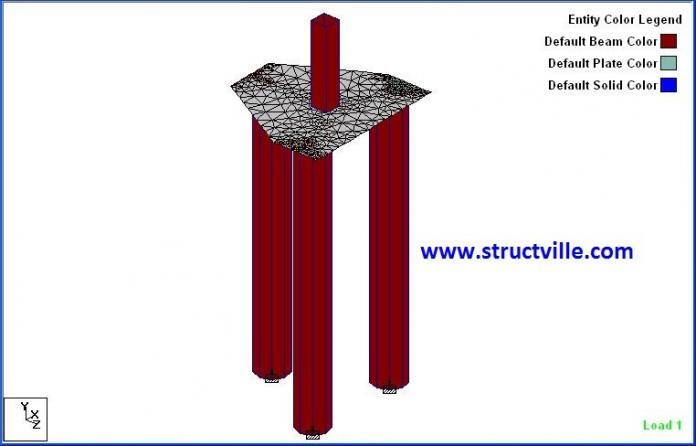
The pile cap was modelled as a 1300 mm thick concrete plate element on Staad Pro, while the piles were modelled as 600 mm diameter columns with a length of 2m supported on a fixed base. The short column was adopted to avoid wide variation of result due to second-order effects and to avoid large displacement which is not very practicable and also not considered in manual analysis.
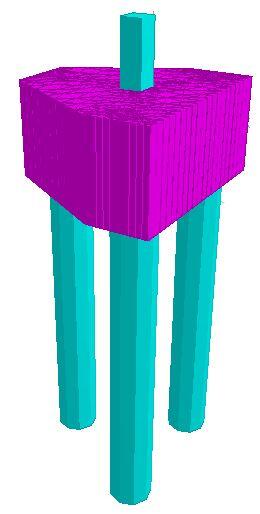
The results obtained from Staad Pro are given in Figures 3 – 6 below;
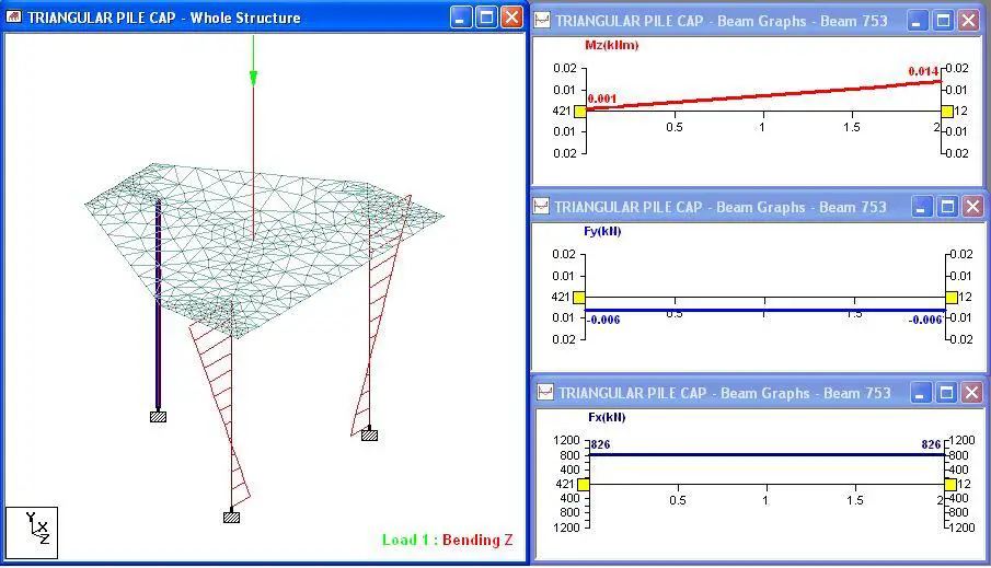
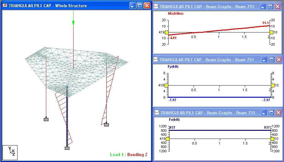
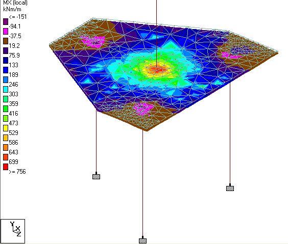
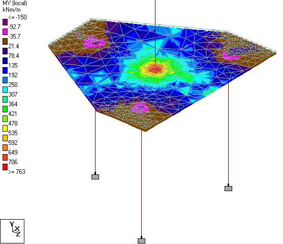
The summary of the results between manual analysis (bending theory) and Staad Pro (finite element analysis) is shown in Table 1.
| Action effect | Bending theory | FEA (Staad Pro) | Percentage difference |
| Single pile load (kN) | 825.32 | 825.77 | 0.054% |
| Twin pile load (kN) | 837.32 | 837.12 | 0.024% |
| Mx (kNm) | 628 | 756.07 | 18.507% |
| My (kNm) | 738.66 | 762.904 | 3.22% |
From Table 1, it could be seen that the distribution of load to the piles was found to be approximately the same for both approaches, but a wide variation was observed for Mx bending moment between the two methods. The My bending moment was found to be close with a percentage difference of about 3.229%.
Therefore, Staad Pro can be used to model triangular pile caps and the result can be used for design purposes. The result obtained from this study is open to discussion, especially based on the difference obtained in bending moment values. We will be glad to hear from you!
To download the full structural analysis and design calculation sheet, click HERE



A perfect analysis in a simple way. Excellence shows in the work.Keep doing things great..Many congrats to Author Ubani…