In civil engineering practice, two methods for modelling structure-soil interaction are commonly used. The beam/plate sitting on an elastic foundation is one way, while the continuum method, which employs finite element analysis (FEA), is another. These approaches take into account the soil and structure deformation.
The Winkler foundation model is connected to the beam/plate resting on an elastic foundation. The Finite Element Analysis (FEA) is a sophisticated method of calculating mechanical problems where the constitutive equation (stress – deformation relationship) determines the outcome of the finite element (FE) computation. Although the FEA is a more advanced method of modeling the interaction, it is still a complicated method that may require a large number of input parameters depending on the model. On the one hand, these input parameters are not always known ahead of time and can be difficult to determine. The Winkler model, on the other hand, just requires one parameter to model the structure-soil interaction.
Soil-structure foundation models can be created in one dimension, two dimensions, or three dimensions. Each of these models has its own set of boundary conditions, calculation method, and, ultimately, advantages and disadvantages when applied to civil engineering calculations.
Models in One Dimension
Analytical or numerical procedures can be used to calculate one-dimensional (1D) models. To characterize the system’s behaviour, an ordinary differential equation can be used which can be solved using the boundary conditions of the system (see analysis beams on elastic foundation). For example, suppose the classical beam theory is used to represent the plate and the Winkler model is used to model the soil (assuming that the soil behavior is entirely linear-elastic). When analyzing slender structures that sit on an elastic foundation, this method is frequently used.
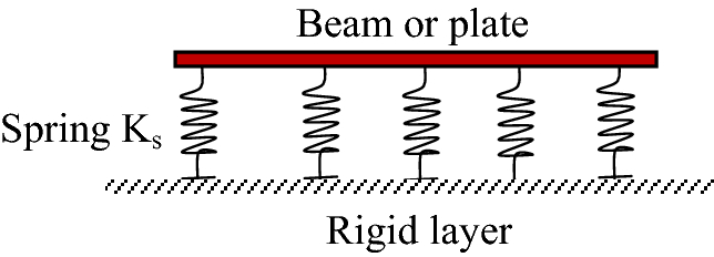
This model has the advantage of taking less time, but it has the disadvantage of being overly basic when it comes to superstructures, particularly slabs. The stiffness parameters for the structure and soil are especially crucial because they are the only parameters in the model that describe the structure and soil medium.
Models in Two Dimensions
This 2D model gives the soil-structure interaction system another dimension and can be used to represent plate structures (see plates on elastic foundation). When using 2D elements in structural software, the soil-structure interaction must be taken into account.
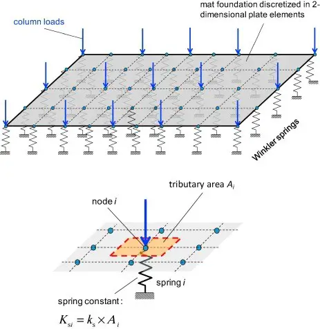
Because of the additional dimension, this model gets near to matching reality. The output results are easy to understand. However, the interaction between the soil and the structure is still difficult to simulate in 2D spaces, which is a disadvantage.
Models in Three Dimensions
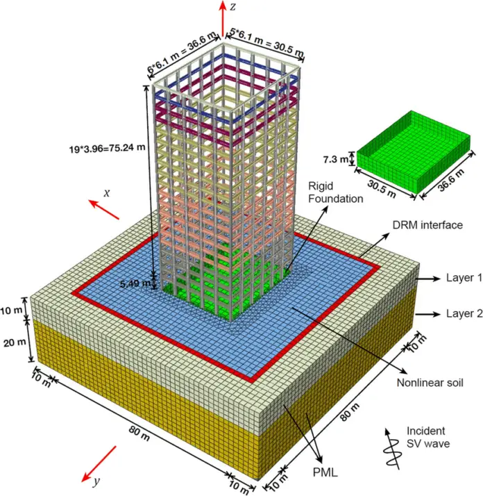
These models are the most accurate representations of reality. All of the dimensions are taken into account. Both the structure, foundation, and soil are modelled using three-dimensional elements.
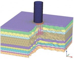
These 3D models have the following advantages:
(1) More dispersal of the loads, which could result in material savings.
(2) Load interactions from several directions are considered.
(3) The model is more accurate.
The disadvantages are as follows:
(1) It is time-consuming (modelling, analysis, and interpretation).
(2) During the design process, not all parameters may be known.
(3) In comparison to a 2D model, the outcomes are more difficult to control.
(4) There is a possibility of apparent accuracy.
Modelling of Soils
For computational analysis, soils are modelled by making some idealisations and following some well-documented approaches which are discussed in the sub-sections below.
Winkler’s Model
The Winkler foundation concept idealizes the soil as a set of springs that displace as a result of the load applied to it. The model has a flaw in that it does not account for the interaction between the springs. Furthermore, a linear stress-strain behavior of the soil is also assumed in the model. This linear relationship simplifies calculations, but the truth is that soil does not exhibit linear elastic behaviour when loaded.
The Wikler model does not portray the settlement in a particularly accurate way, but it does provide an indication of what will happen in reality. The benefit of this model is that it only has one parameter to represent the soil (the modulus of sub-grade reaction, also known as the “k” parameter). This is why it is commonly referred to as a one-parameter model.
For Winklers Model,
p = wk
p = pressure
w = settlement
k = modulus of sub-grade reaction
Pasternak’s Model
Improved versions of the Winkler model have been developed to address the model’s weaknesses. The Pasternak foundation model is one of these variations. The major difference is that the springs in Pasternak’s model are connected to one another. To account for this, it includes an additional factor in addition to the ‘k’ factor, hence this model is also known as a two-parameter model. The word for this is “the Gp parameter.” This parameter physically describes the contact between the spring elements due to shear action. When compared to a one-parameter model, the displacement of the model with this extra parameter can be more realistic.
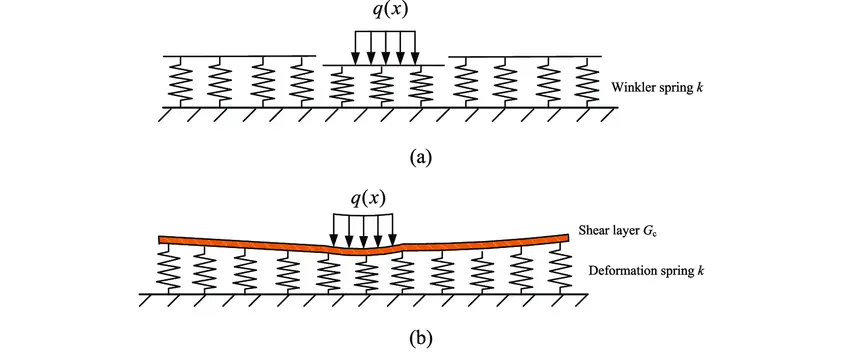
The differential equation is:
p = wk – (Gp)d2w/dx2
p = pressure
k = modulus of sub-grade reaction
Gp = shear modulus of the shear layer
The shear modulus (G) is related to the Gp value, however they are not the same. In a three-dimensional space, their dimensions, G is kN/m2 and Gp is kN/m, show that they are not the same. Gp is G times the effective depth of shearing in the soil. There isn’t a lot of literature or theory on this Gp parameter. Gp is an interaction parameter, according to the available and consulted publications on the Pasternak foundation model. The interaction of the springs is taken into account with this parameter. With this additional parameter, the Winkler model’s flaw is improved. This parameter physically describes the contact between the spring parts owing to shear action.
Soil-Structure Interaction
The difference in stiffness between the structure and the soil can be used to explain the soil-structure interaction. A flexible slab foundation, for example, has the largest settlement in the centre and uniformly distributed contact stresses and low moments. On the other hand, the length of a rigid slab foundation settles uniformly. The contact stresses are higher at the edge because the soil acts more stiffly there since the load can spread there. As a result, the slab’s contact stress has a parabolic shape, with maximum stresses at the edge and minimal values in the centre. The stiff slab’s bending moment is substantially greater than that of a flexible foundation slab.
The interaction between soil and foundation is caused by the linear elastic behavior of the foundation slab and the non-linear elastic behavior of the soil. The difference in stiffness, on the other hand, is the cause of the interaction between structure and soil and can be utilized to explain it.
A method for determining a system’s stiffness category is offered in the literature. The stiffness ratio (kr) can be used for this purpose;
kr = Et3/12EsL3
kr = stiffness ratio
E = young’s modulus of the slab
Es = young’s modulus of the soil
t = thickness of the slab
L = length of the slab
The terms t and L can be straightforwardly determined by the designer, while E and Es can be determined experimentally or using correlations.
For a kr ≤ 0.01 the structure may be defined as flexible and for kr > 0.1 the structure may be defined as stiff.
According to Annex G of EN 1992-1-1:2004, the column forces and the contact pressure distribution on the foundations are both influenced by relative settlements. For general design purposes, the problem can be solved by ensuring that the soil and structure’s displacements and accompanying reactions are compatible.
If the superstructure is considered flexible, then the transmitted loads do not depend on the relative settlements, because the structure has no rigidity. In this case, the loads are no longer unknown, and the problem is reduced to the analysis of a foundation on a deforming ground. If the superstructure is considered rigid, then the unknown foundation loads can be obtained by the condition that settlements should lie on a plane. It should be checked that this rigidity exists until the ultimate limit state is reached.
An analysis comparing the combined stiffness of the foundation, superstructure framing components, and shear walls with the stiffness of the soil can be used to calculate the approximate rigidity of the structural system. Depending on the relative stiffness KR, the foundation or structural system will be considered rigid or flexible. For building structures, expression (G1) of EN 1992-1-1:2004 can be used:
KR = (EJ)S / (EL3)
where:
(EJ)S is the approximate value of the flexural rigidity per unit width of the building structure under consideration, obtained by summing the flexural rigidity of the foundation, of each framed member and any shear wall
E is the deformation modulus of the ground
L is the length of the foundation
Relative stiffnesses higher than 0.5 indicate rigid structural systems.




Very Interesting matter. It educated me a lot. Thanks for sharing your knowledge