During the design and construction of pile foundations, there are instances of eccentric loading that may arise because column positions do not align with the centroid of the pile group. This eccentricity usually induces bending moments which affect the axial load on each pile in a group. Therefore, the evaluation of axial load distribution of piles under eccentric vertical loading is very important, so that the safe working load on each individual pile in not exceeded. In this article, we will discuss the effects of eccentric loading on a group’s axial load on piles.
Every deep foundation project is unique. Most clients frown at soil test reports recommending pile foundations for their projects due to the cost implication of deep foundations. Since there are a variety of pile types, professionals in the construction industry should always assure their clients of the most economical pile type for their projects.
Generally, pile foundations are used when suitable foundation conditions are not present at or near ground level, making the use of shallow traditional foundations uneconomical. Furthermore, it is often recommended to use more than one pile below a column, depending on the pile’s safe working load and the service axial load from the column. Piles in group are usually preferred, particularly if the piles are driven because driven piles in group have large load bearing capacity, a small settlement, and good stability.
Axial Load on Eccentrically Loaded Piles
When a pile group is subjected to eccentric loading, it raises questions about how safe and reliable the piles will become, especially if they were designed initially with zero loading eccentricity. Therefore, designers and construction engineers need to ascertain the eccentricity limit within which a design is still safe and applicable.

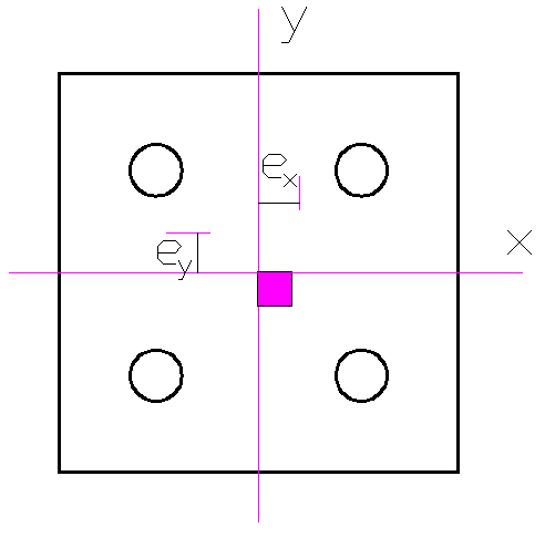
For a group of piles, the vertical load (P) is the sum of the column loads, the self-weight of the pile cap, any backfilling, and the surcharge on the pile cap. Using the figure above, the axial load (Rp) on any pile in a group can be calculated using the equation below.
Rp = P/n ± [(Myy × x)/(∑x2 )] ± [(Mxx × y)/(∑y2)] ———- (1)
Where;
Rp = Axial load on any pile
P = Vertical load on pile group
n = Number of piles in pile group
Mxx and Myy = Moment about x-x and y-y on pile group respectively
x and y = Distance of any pile from x-x and y-y respectively
⅀x2 and ⅀y2 = Sum of the squares of the distances of all piles from x-x and y-y respectively
However, this method of calculating the axial load on any pile in a group is only valid for rigid pile caps, that is, very stiff pile caps. Therefore, large pile caps and rafts should be treated as flexible, and a rigorous grillage or finite element analysis should be undertaken to determine the axial load on any pile.
Solved Example
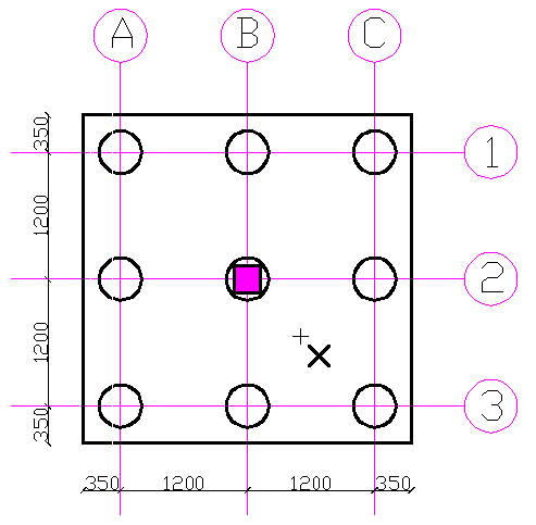
With reference to the pile layout in the diagram below, column position is on grid B2. Column load = 4500 kN. Assuming pile diameter = 400mm, pile cap depth = 900mm, and there is a surcharge load of 18.8 kN/m2
a) Determine the axial load on each pile in the group.
b) If the column moves to a position x, that is, the right of gridline B by 0.3 m and below gridline 2 by 0.6 m simultaneously. What is the effect on the axial load on each pile?

Solution
Column load = 4500 kN
Length and breadth of pile cap = 3100 mm
Pile diameter = 400 mm
Pile cap depth = 900mm
Number of piles (n) = 9
Unit weight of concrete = 24 kN/m3
Surcharge load = 18.8 kN/m2
Vertical load (P) = Column load + Surcharge + self-weight of pile cap
P = 4500 + (18.8 × 3.1 × 3.1) + (3.1 × 3.1 × 0.9 × 24) = 4888.244 kN
a) The axial load on each pile is the same because the vertical load is applied concentrically, and the piles are spaced at sufficient and equal distances apart.
Axial load (Rp) = P/n= 4888.244/9 = 543.14 kN
b) Using equation (1)
⅀x2 = ⅀y2 = (1.2)2 + (1.2)2 + (1.2)2 + (1.2)2 + (1.2)2 + (1.2)2 + (0)2 + (0)2 + (0)2 = 8.64 m
Mxx = Column load × eccentricity = 4500 × 0.6 = 2700 kN
Myy = Column load × eccentricity = 4500 × 0.3 = 1350 kN
PA1 = 4888.244/9 – (1350 × 1.2)/8.64 – (2700 × 1.2)/8.64 = -19.36 kN
PA2 = 4888.244/9 – (1350 × 1.2)/8.64 ± (2700 × 0)/8.64 = 355.64 kN
PA3 = 4888.244/9 – (1350 × 1.2)/8.64 + (2700 × 1.2)/8.64 = 730.64 kN
PB1 = 4888.244/9 ± (1350 x 0)/8.64 – (2700 x 1.2)/8.64 = 168.14 kN
PB2 = 4888.244/9 ± (1350 x 0)/8.64 ± (2700 x 0)/8.64 = 543.14 kN
PB3 = 4888.244/9 ± (1350 x 0)/8.64 + (2700 x 1.2)/8.64 = 918.14 kN
PC1 = 4888.244/9 + (1350 x 1.2)/8.64 – (2700 x 1.2)/8.64 = 355.64 kN
PC2 = 4888.244/9 + (1350 x 1.2)/8.64 ± (2700 x 0)/8.64 = 730.64 kN
PC3 = 4888.244/9 + (1350 x 1.2)/8.64 + (2700 x 1.2)/8.64 = 1105.64 kN
Check
-19.36 + 355.64 + 730.64 + 168.14 + 543.14 + 918.14 + 355.64 + 730.64 + 1105.64 = 4888.260 kN ~ Vertical load (P = 4888.244 kN)
Conclusion
From the solved example above, we can see that loading eccentricity significantly impacts the axial load on any pile in a pile group. Moreover, the effect is quite profound on PC3, with a 103.6% increment in axial load compared to when the vertical load (P) acts on the pile group concentrically.
Furthermore, piles are usually designed to transfer compression loads. As a result of the eccentric loading of the pile group, PA1 is now in tension. This means the pile is subjected to uplift forces that might otherwise cause it to be pulled out of the ground. Therefore, the pile group will fail if the piles are not designed to resist uplift forces.
Construction engineers must give more attention to the positioning of columns to ensure that column centerlines align with the centroid of pile groups. Indeed, the load capacity of piles is usually factored by 2 – 2.5, but this should not prevent construction engineers from constructing with due diligence.
Reference(s)
[1] Di Laora, R., de Sanctis, L. & Aversa, S. Bearing capacity of pile groups under vertical eccentric load. Acta Geotech. 14, 193–205 (2019). https://doi.org/10.1007/s11440-018-0646-5


I will lake to know more about full pile Design and how to adentifine soil types in foundation Geotechnical.