Cost is a major controlling factor in civil engineering construction projects. Different types of floor systems are adopted in reinforced concrete slab designs such as solid slabs, waffle slabs, ribbed slabs, flat slabs, etc. Each floor system has its advantages, applications, and cost implications in construction. This article aims to evaluate the cost comparison of solid and ribbed slabs.
The idea behind the adoption of the ribbed slab system is the need to reduce the volume of concrete in the tension zone of a concrete slab. Theoretically, the tensile strength of concrete is assumed to be zero during the structural design of flexural structural elements such as beams and slabs. By implication, all the tensile stresses from bending are assumed to be resisted by the reinforcements (see the stress block of flexural concrete sections in Figure 1).
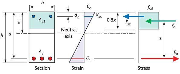
If concrete is assumed to do no work in the tension zone, it then makes economical sense to reduce the volume of concrete in that zone (bottom of the slab). To achieve this, beams of relatively shallow depths (ribs) are spaced at intervals to resist the flexural stresses due to the bending of the floor, with a thin topping (of about 50 mm). When this is done, a thick volume of concrete is no longer uniformly provided in the tensile zone of the concrete.
As the span of a floor increases, the thickness of the concrete and the quantity of reinforcements required to satisfy ultimate and serviceability limit state requirements also increase. However, by introducing ribbed slabs, longer spans can be economically spanned.
To reduce the cost and labour of constructing ribbed slabs, clay hollow pots, sandcrete blocks, or polystyrene are usually provided as infills between the ribs. While clay hollow pots and sandcrete blocks will improve the stiffness of the floor, the same, however, cannot be confidently said about polystyrenes.

There are significant cost implications of adopting either solid or ribbed slabs. In a study by Ajema and Abeyo (2018), they observed that frames with solid slabs are more economical than frames with a ribbed slab when subjected to seismic action. In another study by Nassar and Al-Qasem (2020) on the cost of different slab systems, they observed that the flat slab system reduces the total cost of construction by 7% compared to the solid slab system, 4 % compared to the one-way ribbed slab system, and 3.33% compared to the two-way ribbed slab system.
Mashri et al (2020) compared the cost of constructing solid slabs and hollow block ribbed slabs and concluded that ribbed slabs are cheaper than solid slabs. In a study on the assessment of the cost difference between solid and hollow floors, Dosumu and Adenuga (2013) observed that the cost of in-situ solid slabs are higher than that of hollow slab provided the hollow slab is a one-way hollow floor and not a waffle floor.
However, it is important to note that the scenario on the issue of cost can vary depending on the size and geometry of the slab. For short one-way slabs, solid slabs may be cheaper than ribbed slabs, while in large-span two-way slabs, ribbed slabs may be cheaper than solid slabs.
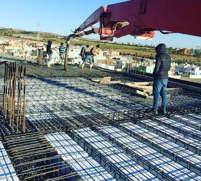
With the aid of design examples and quantity estimation, let us compare the cost of constructing a two-way slab of dimensions 5.225m x 7.426m that is discontinuous at all edges using ribbed slab and solid slab. The slab is to support a live load of 2.5 kN/m2.
Design of Ribbed Slab
Reinforcement details
Characteristic yield strength of reinforcement; fyk = 410 N/mm2
Partial factor for reinforcing steel – Table 2.1N; γS = 1.15
Design yield strength of reinforcement; fyd = fyk/γS = 357 N/mm2
Concrete details
Concrete strength class; C25/30
Aggregate type; Quartzite
Aggregate adjustment factor – cl.3.1.3(2); AAF = 1.0
Characteristic compressive cylinder strength; fck = 25 N/mm2
Mean value of compressive cylinder strength; fcm = fck + 8 N/mm2 = 33 N/mm2
Mean value of axial tensile strength; fctm = 0.3 N/mm2 × (fck)2/3 = 2.6 N/mm2
Secant modulus of elasticity of concrete; Ecm = 22 kN/mm2 × (fcm/10)0.3 × AAF = 31476 N/mm2
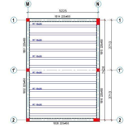
Design Information
Spacing of ribs = 450 mm
Topping = 50 mm
Rib width = 150 mm
Span = 5.225 m (simply supported)
Total depth of slab = 250 mm
Design live load qk = 2.5 kN/m2
Weight of finishes = 1.2 kN/m2
Partition allowance = 1.5 kN/m2
Load Analysis
Dead Load
Self-weight of topping = 24 × 0.05 × 0.45 = 0.54 kN/m
Self-weight of ribs = 24 × 0.15 × 0.2 = 0.72 kN/m
Weight of finishes = 1.2 × 0.45 = 0.54 kN/m
Partition allowance = 1.5 × 0.45 = 0.675 kN/m
Self-weight of heavy duty EPS = (0.156 × 0.2 × 0.45) = 0.014 kN/m
Total dead load per rib gk = 2.489 kN/m
Live Load
Characteristic live load = 2.5 kN/m2
Total live load per rib = 2.5 × 0.45 = 1.125 kN/m
At ultimate limit state;
PEd = 1.35gk + 1.5qk = 1.35(2.489) + 1.5(1.125) = 5.047 kN/m
Flexural Design
Design bending moment; MEd = 17.2 kNm
Effective flange width; beff = 2 × beff,1 + b = 450 mm
Effective depth of tension reinforcement; d = 209 mm
K = M / (beff × d2 × fck) = 0.035
K’ = 0.207
Lever arm; z = 199 mm
Depth of neutral axis; x = 2 × (d – z) / l = 26 mm
lx <= hf – Compression block wholly within the depth of flange
K’ > K – No compression reinforcement is required
Area of tension reinforcement required; As,req = M / (fyd × z) = 243 mm2
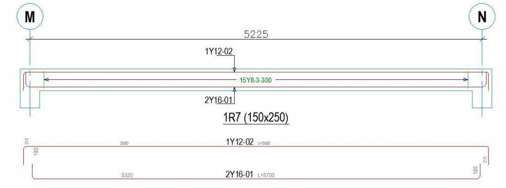
Tension reinforcement provided; 2Y16 (As,prov = 402 mm2)
Minimum area of reinforcement – exp.9.1N; As,min = max(0.26 × fctm / fyk, 0.0013) × b × d = 51 mm2
Maximum area of reinforcement – cl.9.2.1.1(3); As,max = 0.04 × b × h = 1500 mm2
PASS – Area of reinforcement provided is greater than area of reinforcement required
Deflection control
Reference reinforcement ratio; ρm0 = (fck )0.5 / 1000 = 0.00500
Required tension reinforcement ratio; ρm = As,req / (beff × d) = 0.00259
Required compression reinforcement ratio; ρ’m = As2,req / (beff × d) = 0.00000
Structural system factor – Table 7.4N; Kb = 1.0
Basic allowable span to depth ratio ; span_to_depthbasic = Kb × [11 + 1.5 × (fck)0.5 × ρm0 / ρm + 3.2 × (fck)0.5 × (ρm0 / ρm – 1)1.5] = 39.900
Reinforcement factor – exp.7.17; Ks = min(As,prov / As,req × 500 N/mm2 / fyk, 1.5) = 1.500
Flange width factor; F1 = if(beff / b > 3, 0.8, 1) = 1.000
Long span supporting brittle partition factor; F2 = 1.000
Allowable span to depth ratio; span_to_depthallow = min(span_to_depthbasic × Ks × F1 × F2, 40 × Kb) = 40.000
Actual span to depth ratio; span_to_depthactual = Lm1_s1 / d = 25.000
PASS – Actual span to depth ratio is within the allowable limit
Shear Design
Angle of comp. shear strut for maximum shear; θmax = 45 deg
Strength reduction factor – cl.6.2.3(3); v1 = 0.6 × (1 – fck / 250 N/mm2) = 0.540
Compression chord coefficient – cl.6.2.3(3); acw = 1.00
Minimum area of shear reinforcement – exp.9.5N; Asv,min = 0.08 N/mm2 × b × (fck )0.5 / fyk = 146 mm2/m
Design shear force at support ; VEd,max = 13 kN
Min lever arm in shear zone; z = 199 mm
Maximum design shear resistance – exp.6.9; VRd,max = acw × b × z × v1 × fcwd / (cot(θmax) + tan(θmax)) = 134 kN
PASS – Design shear force at support is less than maximum design shear resistance
Design shear force at 209 mm from support; VEd = 12 kN
Design shear stress; vEd = VEd / (b × z) = 0.407 N/mm2
Area of shear reinforcement required – exp.6.8; Asv,des = vEd × b / (fyd × cot(θ)) = 69 mm2/m
Area of shear reinforcement required; Asv,req = max(Asv,min, Asv,des) = 146 mm2/m
Shear reinforcement provided; 2Y 8 legs @ 150 c/c
Area of shear reinforcement provided; Asv,prov = 670 mm2/m
PASS – Area of shear reinforcement provided exceeds minimum required
Maximum longitudinal spacing – exp.9.6N; svl,max = 0.75 × d = 157 mm
PASS – Longitudinal spacing of shear reinforcement provided is less than maximum
However, calculations have shown that shear reinforcements are not required since VEd (13 kN) is less than VRdc (25.2 kN). According to clause 6.2.1(4) of EN 1992-1-1:2004, when, on the basis of the design shear calculation, no shear reinforcement is required, minimum shear reinforcement should nevertheless be provided according to clause 9.2.2. The minimum shear reinforcement may be omitted in members such as slabs (solid, ribbed or hollow core slabs) where transverse redistribution of loads is possible.
Therefore to save cost, let us provide a triangular pattern link spaced at 300mm c/c, and 1Y12 (Asprov = 113 mm2) at the top of the rib.

Design of Solid Slab
RC slab design
In accordance with EN1992-1-1:2004 incorporating corrigendum January 2008 and the UK national annex
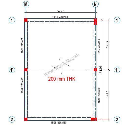
Slab definition
Type of slab; Two way spanning with restrained edges
Overall slab depth; h = 200 mm
Shorter effective span of panel; lx = 5225 mm
Longer effective span of panel; ly = 7426 mm
Support conditions; Four edges discontinuous
Loading
Characteristic permanent action; Gk = 6.5 kN/m2
Characteristic variable action; Qk = 2.5 kN/m2
Partial factor for permanent action; γG = 1.35
Partial factor for variable action; γQ = 1.50
Quasi-permanent value of variable action; ψ2 = 0.30
Design ultimate load; q = γG × Gk + γQ × Qk = 12.5 kN/m2
Quasi-permanent load; qSLS = 1.0 × Gk + ψ2 × Qk = 7.2 kN/m2
Concrete properties
Concrete strength class; C25/30
Characteristic cylinder strength; fck = 25 N/mm2
Partial factor (Table 2.1N); γC = 1.50
Compressive strength factor (cl. 3.1.6); acc = 0.85
Design compressive strength (cl. 3.1.6); fcd = 14.2 N/mm2
Mean axial tensile strength (Table 3.1); fctm = 0.30 N/mm2 × (fck )2/3 = 2.6 N/mm2
Maximum aggregate size; dg = 20 mm
Reinforcement properties
Characteristic yield strength; fyk = 410 N/mm2
Partial factor (Table 2.1N); γS = 1.15
Design yield strength (fig. 3.8);fyd = fyk / γS = 356.5 N/mm2
Concrete cover to reinforcement
Nominal cover to outer bottom reinforcement; cnom_b = 25 mm
Fire resistance period to bottom of slab; Rbtm = 60 min
Axial distance to bottom reinft (Table 5.8); afi_b = 10 mm
Min. btm cover requirement with regard to bond; cmin,b_b = 12 mm
Reinforcement fabrication; Not subject to QA system
Cover allowance for deviation; Dcdev = 10 mm
Min. required nominal cover to bottom reinft; cnom_b_min = 22.0 mm
PASS – There is sufficient cover to the bottom reinforcement
Reinforcement design at midspan in short span direction (cl.6.1)
Bending moment coefficient; bsx_p = 0.0881
Design bending moment; Mx_p = bsx_p × q × lx2 = 29.9 kNm/m
Reinforcement provided; 12 mm dia. bars at 200 mm centres
Area provided; Asx_p = 565 mm2/m
Effective depth to tension reinforcement; dx_p = h – cnom_b – fx_p / 2 = 169.0 mm
K factor; K = Mx_p / (b × dx_p2 × fck) = 0.042
Redistribution ratio; δ = 1.0
K’ factor; K’ = 0.598 × d – 0.18 × d2 – 0.21 = 0.208
K < K’ – Compression reinforcement is not required
Lever arm; z = min(0.95 × dx_p, dx_p/2 × (1 + √(1 – 3.53 × K))) = 160.5 mm
Area of reinforcement required for bending; Asx_p_m = Mx_p / (fyd × z) = 523 mm2/m
Minimum area of reinforcement required; Asx_p_min = max(0.26 × (fctm/fyk) × b × dx_p, 0.0013 × b × dx_p) = 275 mm2/m
Area of reinforcement required; Asx_p_req = max(Asx_p_m, Asx_p_min) = 523 mm2/m
Check reinforcement spacing
Reinforcement service stress; ssx_p = (fyk / gS) × min((Asx_p_m/Asx_p), 1.0) × qSLS / q = 190.7 N/mm2
Maximum allowable spacing (Table 7.3N); smax_x_p = 262 mm
Actual bar spacing; sx_p = 200 mm
PASS – The reinforcement spacing is acceptable
Reinforcement design at midspan in long span direction (cl.6.1)
Bending moment coefficient; bsy_p = 0.0560
Design bending moment; My_p = bsy_p × q × lx2 = 19.0 kNm/m
Reinforcement provided; 12 mm dia. bars at 250 mm centres
Area provided; Asy_p = 452 mm2/m
Effective depth to tension reinforcement; dy_p = h – cnom_b – fx_p – fy_p / 2 = 157.0 mm
K factor; K = My_p / (b × dy_p2 × fck) = 0.031
Redistribution ratio; d = 1.0
K’ factor; K’ = 0.598 × d – 0.18 × d2 – 0.21 = 0.208
K < K’ – Compression reinforcement is not required
Lever arm; z = min(0.95 × dy_p, dy_p/2 × (1 + √(1 – 3.53 × K))) = 149.2 mm
Area of reinforcement required for bending; Asy_p_m = My_p / (fyd × z) = 358 mm2/m
Minimum area of reinforcement required; Asy_p_min = max(0.26 × (fctm/fyk) × b × dy_p, 0.0013 × b × dy_p) = 255 mm2/m
Area of reinforcement required; Asy_p_req = max(Asy_p_m, Asy_p_min) = 358 mm2/m
PASS – Area of reinforcement provided exceeds area required
Check reinforcement spacing
Reinforcement service stress; ssy_p = (fyk / γS) × min((Asy_p_m/Asy_p), 1.0) × qSLS / q = 163.1 N/mm2
Maximum allowable spacing (Table 7.3N); smax_y_p = 296 mm
Actual bar spacing; sy_p = 250 mm
PASS – The reinforcement spacing is acceptable
Basic span-to-depth deflection ratio check (cl. 7.4.2)
Reference reinforcement ratio; ρ0 = (fck)0.5 / 1000 = 0.0050
Required tension reinforcement ratio; ρ = max(0.0035, Asx_p_req / (b × dx_p)) = 0.0035
Required compression reinforcement ratio; ρ’ = Ascx_p_req / (b × dx_p) = 0.0000
Structural system factor (Table 7.4N); Kd = 1.0
Basic limit span-to-depth ratio (Exp. 7.16);
ratiolim_x_bas = Kd × [11 +1.5 × (fck)0.5 × ρ0/ρ + 3.2 × (fck)0.5 × (ρ0/ρ -1)1.5] = 26.20
Mod span-to-depth ratio limit;
ratiolim_x = min(40 × Kd, min(1.5, (500 N/mm2/ fyk) × (Asx_p / Asx_p_m)) × ratiolim_x_bas) = 34.54
Actual span-to-eff. depth ratio; ratioact_x = lx / dx_p = 30.92
PASS – Actual span-to-effective depth ratio is acceptable
Reinforcement summary
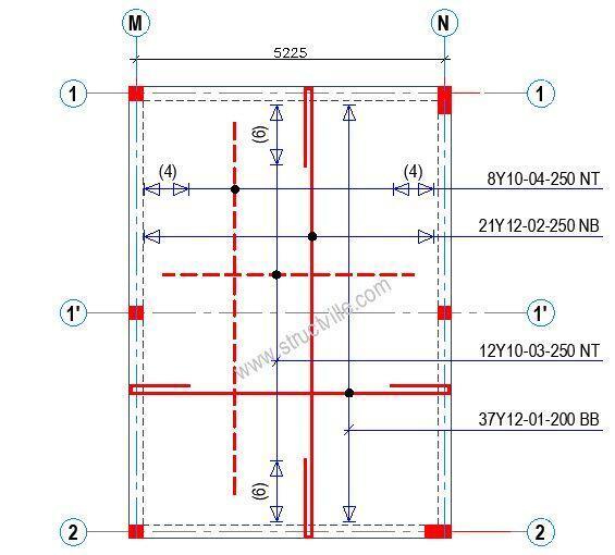
Midspan in short span direction; 12 mm dia. bars at 200 mm centres B1
Midspan in long span direction; 12 mm dia. bars at 250 mm centres B2
Discontinuous support in short span direction; 12 mm dia. bars at 200 mm centres B1
Discontinuous support in long span direction; 12 mm dia. bars at 250 mm centres B2

Cost Comparison of Solid and Ribbed Slabs
In this section, we are going to consider the cost of constructing ribbed slab and the cost of constructing solid slabs (considering the cost of materials only). In this case, the cost of labour is assumed to be directly proportional to the quantity of materials.
Cost analysis of solid slab
Concrete
Volume of concrete required for the slab = 5.45 × 7.65 × 0.2 = 8.3385 m3
Current unit cost of concrete materials = ₦55,000/m3
Cost of concrete materials = 8.3385 × 55000 = ₦ 458,618
Quantity of steel required
Bar mark 1 = 37 × 7.645 × 0.888 = 251.184 kg
Bar mark 2 = 21 × 10.485 × 0.888 = 195.524 kg
Bar mark 3 = 12 × 4.225× 0.617 = 31.28 kg
Bar mark 3 = 8 × 6.625 × 0.617 = 32.701kg
Total = 510.689 kg
Unit cost of reinforcement = ₦ 450/kg
Cost of reinforcement = 510.689 × 450 = ₦ 229,810
Formwork Required
Soffit of slab = 36 m2 (treated as a constant)
Cost of constructing solid slab = ₦ 229,810 + ₦ 458,618 = ₦ 688,428
Cost Analysis of Ribbed Slab
Concrete
Volume of concrete required for the topping = 5.45 × 7.65 × 0.05 = 2.084 m3
Volume of concrete required for the ribs = 12 × 0.2 × 0.15 × 5 = 1.8 m3
Total volume of concrete = 3.884 m3
Cost of concrete materials = 3.884 × 55,000 = ₦ 213,620
Quantity of steel required
Bar mark 1 = 2 × 12 × 5.7 × 1.579 = 216 kg
Bar mark 2 = 1 × 12 × 5.8 × 0.888 = 61.8 kg
Bar mark 3 (triangular links) = 17 × 12 × 0.612 × 0.395 = 49.314 kg
Total = 327.114 kg
Cost of reinforcement = 327.114 × 450 = ₦ 147,205
BRC Mesh for Topping (A142) – 41.7 m2
Unit cost of BRC mesh = ₦ 1580/m2
Cost of BRC mesh = 41.7 × 1580 = ₦ 65,886
Total cost of reinforcement works = 147,205 + 65,886 = ₦ 213,620
Clay hollow pot/Sandcrete Blocks/Polystyrene
Number of block units required = 240 units
Unit price of hollow blocks = NGN 400 per unit
Cost of hollow blocks = 240 × 400 = ₦ 96,000
Formwork Required
Soffit of slab = 36 m2 (treated as a constant)
Cost of constructing ribbed slab = ₦ 213,620 + ₦ 213,091 + ₦ 96,000 = ₦ 522,711
The Table for comparison is shown below;
| Material | Solid Slab | Ribbed Slab | Percentage Reduction |
| Concrete | ₦ 458,618 | ₦ 213,620 | 53.42% |
| Reinforcement | ₦ 229,810 | ₦ 213,620 | 7.04% |
| Hollow Pots/Blocks | – | ₦ 96,000 | – |
| Total | ₦ 688,428 | ₦ 522,711 | 24.07% |
Conclusion
From the analysis of the two-way slab carried out, it can be seen that the volume of concrete required for a ribbed slab is 53.42% less than that required for a solid slab. Furthermore, the reinforcement required in the ribbed slab is 7.04% less than that required for a solid slab. If the same type of formwork is adopted (completely flat soffit supported with props), and if the cost of labour is directly related to the quantity of materials, then the adoption of the ribbed slab is expected to save cost by about 24.07% compared to solid slab.
References
[1] Ajema D. and Abeyo A. (2018): Cost Comparison between Frames with Solid Slab and Ribbed Slab using HCB under Seismic Loading. International Research Journal of Engineering and Technology 05(01):109-116
[2] Dosumu O. S. and Adenuga O. A.(2013): Assessment of Cost Variation in Solid and Hollow Floor Construction in Lagos State. Journal of Design and Built Environment 13(1):1-11
[3] Mashri M., Al-Ghosni K., Abdulrahman A., Ismaeil M., Abdussalam A. and Elbasir O. M. M. (2020):Design and cost comparison of the Solid Slabs and Hollow Block Slabs. GSJ 8(1):110-118 www.globalscientificjournal.com
[4] Reema R. Nassar 1, Imad A. Al-Qasem 2 (2020): Comparative Cost Study for A residential Building Using Different Types of Floor System. International Journal of Engineering Research and Technology 13(8): 1983-1991

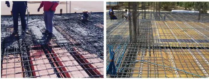








due to the weight reduction, the net saving by using ribbed slab will be more than 24.07% due to the reduction in sizes of column, beam and foundation members.