When two structural elements are designed to move relative to one another, an expansion joint is usually required to seal the gap between the two elements while also accommodating their relative movements. Expansion joints in bridges are usually provided to allow for thermal expansion and contraction of the bridge deck, and to also allow for movement due to traffic actions on the bridge. The gap between the deck end and the abutment wall is frequently the case for bridges. On long viaducts or continuous bridges, however, additional joints may be required between deck portions to limit the movement at any one place.
Expansion joints are a point of weakness within a bridge due to its function, and there have been several occurrences of joints leakage, which can cause problems to the bridge. For example, corrosion of the bridge reinforcement has commonly occurred when de-icing salt-laden water has seeped onto bearing shelves or pier supports.
The required repairs are substantially more expensive than the joint’s initial capital cost, especially when traffic delays are included. It is therefore important to pay careful attention to the design, detailing, and installation of bridge expansion joints in order to reduce the risk of future high repair costs for the bridge owner.
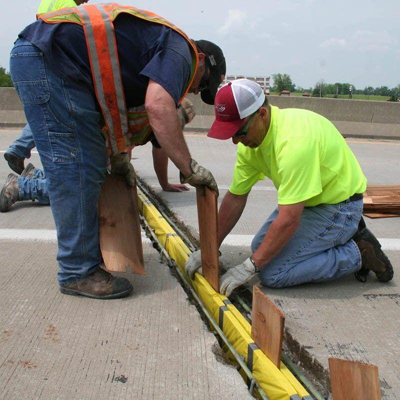
One of the main reasons for the rising use of integral bridge design is the susceptibility of expansion joints. Integral bridge construction eliminates the requirement for expansion joints by attaching the deck directly to the abutments. The removal of expansion joints is often recommended where possible due to the problems they can cause.
An integral bridge, on the other hand, will have the same load effects and causes of movement as an expansion joint, however, the effects of the movement will need to be considered in its design. However, integral construction will not be a possibility for many bridges, especially those already built, and expansion joints will always be required.
Performance Criteria of Expansion Joints in Bridges
For an expansion joint to function well, it must possess a number of qualities. Some of them are listed below;
- It must withstand loads and movements without causing failure to itself or other sections of the structure.
- It should be watertight
- It should provide a smooth ride, and pose no danger to road users such as cyclists, pedestrians, or equestrians.
- The joint’s skid resistance should equal that of nearby surfacing
- Noise emissions from the expansion joint should be kept to a minimum, especially if it’s going to be used in residential areas.
- The joint should be easy to inspect and maintain.
Types of Expansion Joints in Bridges
Different types of expansion joint are presented below, together with an indication of typical movement ranges for each type of joint. Different types of expansion joints are listed in Reid et al (2008) and reproduced here.
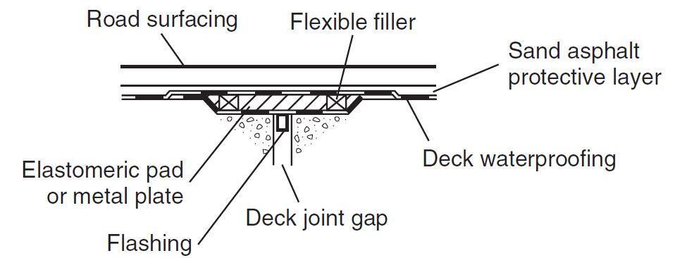
Buried Expansion Joint
This expansion joint is essentially covered by the road surfacing. It permits movement up to 20 mm (±10 mm). For movements up to 10 mm the joint can be formed on top of the deck using a flashing and waterproofing layer to bridge the gap. For larger movements the flashing is dropped down into a recess below the top of the deck and an elastomeric pad used to fill the recess.
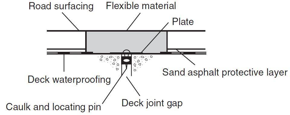
Asphaltic Plug Expansion Joint
This expansion joint consists of an in-situ joint of flexible bituminous material, which provides both an expansion medium and the running surface. The deck joint gap is covered by a thin plate. It permits a movement range of up to 40 mm (±20 mm).
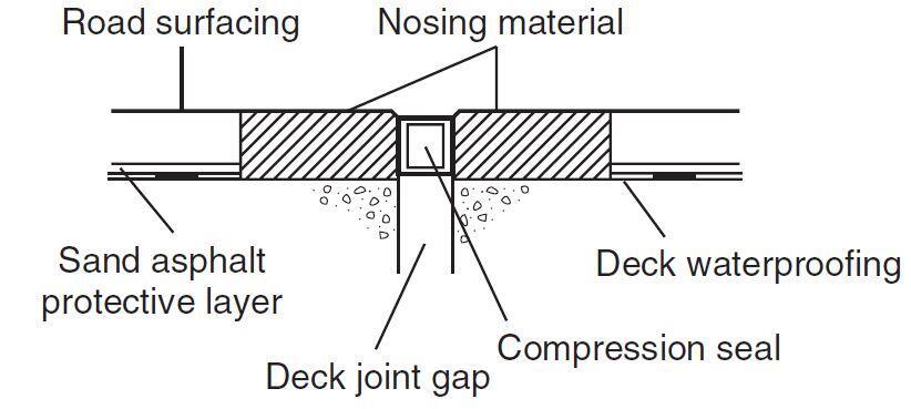
Nosing Expansion Joint
This type of joint consists of a relatively stiff nosing material of cementitious polyurethane, polyuride or epoxy binders protects the adjacent edges of the surfacing and a compression seal (or poured sealant) protects against ingress of water. It permits a movement range of up to 12 mm with poured sealant and up to 40 mm with a preformed compression seal.
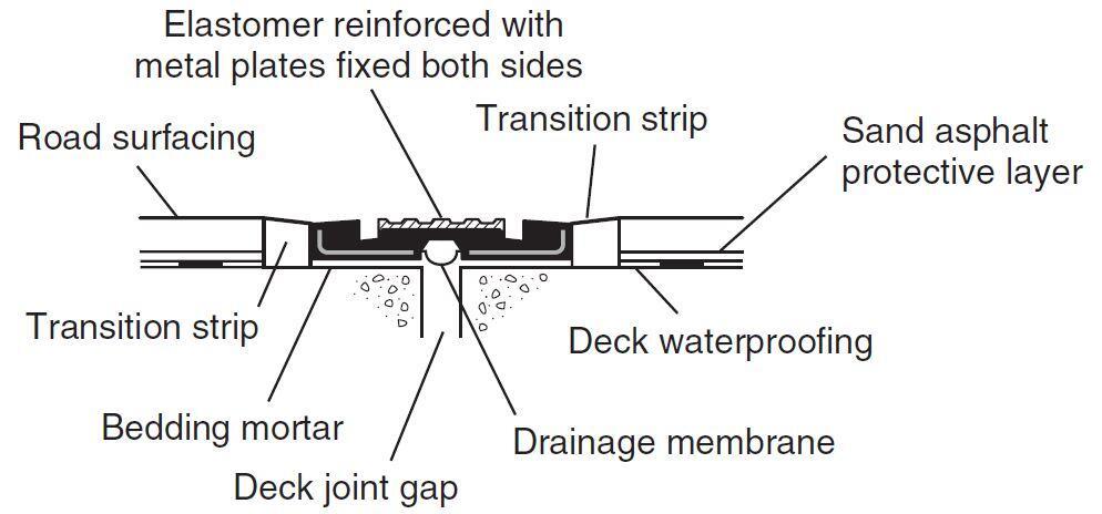
Reinforced Elastomeric Expansion Joint
This joint consists of a prefabricated segmental joint of neoprene rubber with reinforcing angles and plates. It is bolted down to the concrete and epoxy resin mortar nosing transition strips protect the adjacent surfacing. There are various sizes giving movement range of up to ±165 mm.
Elastomeric in Metal Runners Expansion Joint
In this type of expansion joint, an elestomeric seal is fixed between two metal runners cast into recesses in the abutment and deck concrete. By introducing intermediate runners, multi-element joints can be provided (as illustrated) with greater capacity. As an alternative the rails can be embedded in a resin bonded to the concrete or a rubber element bolted to the concrete.
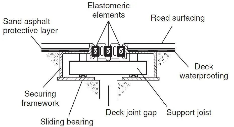
Movement range:
Single element up to 80 mm (±40 mm)
Multi-element up to 960 mm (±480 mm)
Embedded up to 150 mm (±75 mm)
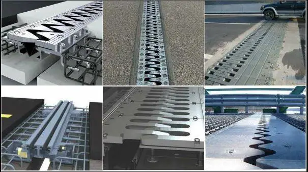
Cantilever Comb or Tooth Expansion Joint
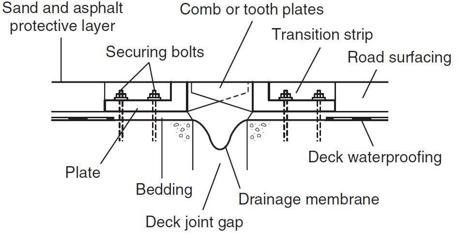
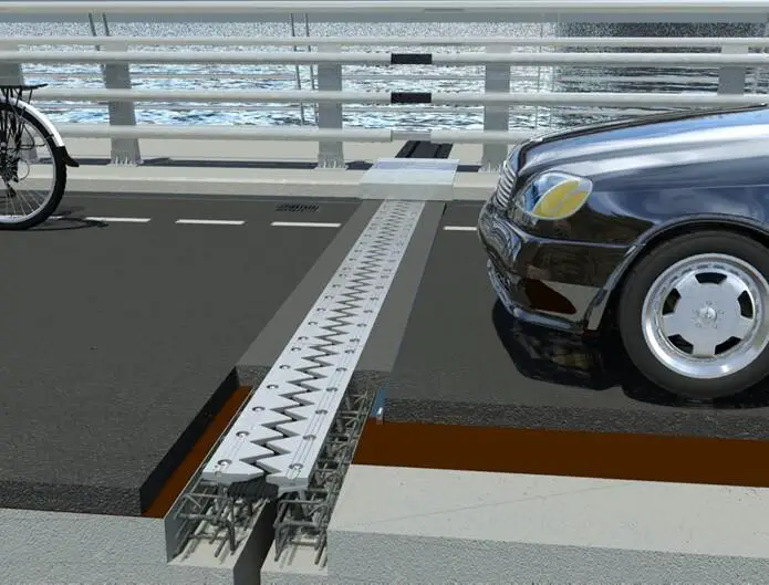
In this type of expansion joint, a prefabricated joint in which metal comb or tooth plates slide back and forth between each other across the gap. They are bolted down to the concrete and a drainage membrane is provided underneath to collect water. The movement range is typically up to 600 mm (±300 mm).
A variety of factors will influence the selection of the type of expansion joint for bridges. On an individual joint, different types of joints should not be mixed, and this will often define the type of maintenance work performed on an existing joint. For novel applications, the joint must clearly be able to accommodate the anticipated movements, but there are other factors to consider when evaluating the joint’s performance.
The treatment of the verges and footways, which may contain a variety of services, the road alignment (gradient, cross-fall, and curvature), the vicinity of junctions (where longitudinal loads will be more common), and how heavily trafficked the joint will be are all factors to consider. All of these factors can affect the performance and hence the life of an expansion joint, and they must be considered when calculating the total cost of the joint.
Design of Expansion Joints in Bridges
In the UK, BD 33 specifies the design loads and movements for expansion joints (Highways Agency, 1994a). Expansion joints in bridges should be designed for both serviceability and ultimate limit states to ensure that they function well without requiring unnecessary maintenance and that they can withstand ultimate design loads and movements.
For vertical loads, BD 33 specifies a 100kN single wheel load or a 200kN single axle load with a 1.8m track, as well as an 80 kN/m horizontal load. Vertical loads at the ultimate limit state (ULS) and serviceability limit state (SLS) have partial load factors of 1.50 and 1.20, respectively, whereas horizontal loads have partial load factors of 1.25 and 1.00. There are two key elements to remember.
In the Eurocodes, it is important to determine the traffic loads and combinations on expansion joints for (quasi-) static assessment at Ultimate Limit State and, where requested at Serviceability Limit State, and fatigue loads and relevant conditions for assessment of seismic behaviour. It shall be used in combination with pre-stressing, imposed deformations, dead loads and seismic loads.
Furthermore, it is important to verify and guarantee;
- The movement capacity,
- The water tightness,
- The drainage capacity,
- The content, emission and/or release of dangerous substances.
The vertical and horizontal loads for design of expansion joints are derived from EN 1991-2, 4.3, Load Model 1. Only tandem systems TS apply, not the uniformly distributed loads (UDL) as they are not relevant for the expansion joints. The selected position(s) of the axle loads shall be such that they produce the most adverse load effect on the underlying structure between the kerbs. This may result in several load cases with different positions.
First, the supporting structure should be designed to sustain the above loads. Second, to the above loads should be added those resulting from strains developed in the joint fillers over their design range of movement.

At both ULS and SLS, calculation of movements are based on partial load factors of unity. Joint movements can come from a variety of sources, and they should all be added up to get a total movement range from which to choose a joint type. Because not all movements are reversible, it is desirable to analyse and establish limitations for both the closure and opening of the joint, rather than just the overall range of movement, because it is unclear if movements in either direction balance.
Temperature changes are determined by the effective bridge temperatures experienced by the deck and should be assessed in line with the applicable bridge design standard. Irreversible movements are caused by concrete creep and shrinkage, and they must be assessed using concrete or composite bridge design standards.
On curved or skew bridges, lateral movement of the joint should be considered because it can alter the joint design. Movements can be caused by settlement of supports, as well as sway of the bridge under longitudinal braking or traction stresses, depending on the articulation of the bridge. Rotation of the deck ends under live load on bridges with flexible or deep decks can produce significant displacement at the joint level. This explains why even a joint located above a fixed bearing will move. Installing the expansion joint as late as possible, after the majority of permanent movements have already occurred, avoids a comparable impact for permanent loads.
Drainage of Expansion Joints
Expansion joints rarely fail because their maximum movement capacity is surpassed. This is ensured by partial factors of safety embedded into their design. Because they are locally subjected to higher than expected stresses, parts of joints may deteriorate more quickly on occasion, maybe due to increased dynamic influences on wheel loads induced by uneven pavement.
Water leaks through the joints is usually the main cause of failure. This can be caused by inadequate joint details, poor installation technique, or just the inherent challenge of completely sealing any junction between two pieces moving relative to each other. Water management on the bridge deck is critical to an expansion joint’s success, and it should be addressed early in the design process rather than as an afterthought.
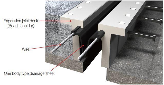
While every effort should be made to make expansion joints waterproof, there is always the possibility of water from the surface leaking through the joint over time. It is usual practice to install a drainage system beneath the deck joint gap to collect water that leaks through the expansion joint. This system should allow for easy inspection and maintenance, as well as discharge into a proper road drainage system or soak away.
Before it reaches the expansion joint, water coming through the surfacing and running along the waterproofing should be collected and discharged through a subsurface drainage system.
Detailing of Expansion Joints
Good expansion joint details will go a long way toward making the joint low-maintenance and functional. A variety of regulations relating to bridge user safety are included in the Highways Agency document BD 33. Any open gap not bridged by a load-bearing part, for example, shall not be wider than 65 mm, and no gaps are allowed where pedestrians have access to the bridge.
A loadbearing seal or a cover plate can be used to solve this problem. Cover plates should be contoured and positioned in shallow recesses in the footway to prevent slipping. On one side of the joint, they are bolted, but on the other, they can slide. These plates are normally 12mm thick since they must withstand inadvertent wheel stresses. Over the parapet string course, thinner cover plates are frequently installed to hide what would otherwise be an open expansion junction.
At these potentially impact-prone locations, kerb cover plates should be provided to protect the expansion joint. To guarantee that cyclists may ride through tooth-and-comb joints where the gaps are oriented generally in the direction of traffic, extra care must be exercised during the installation.
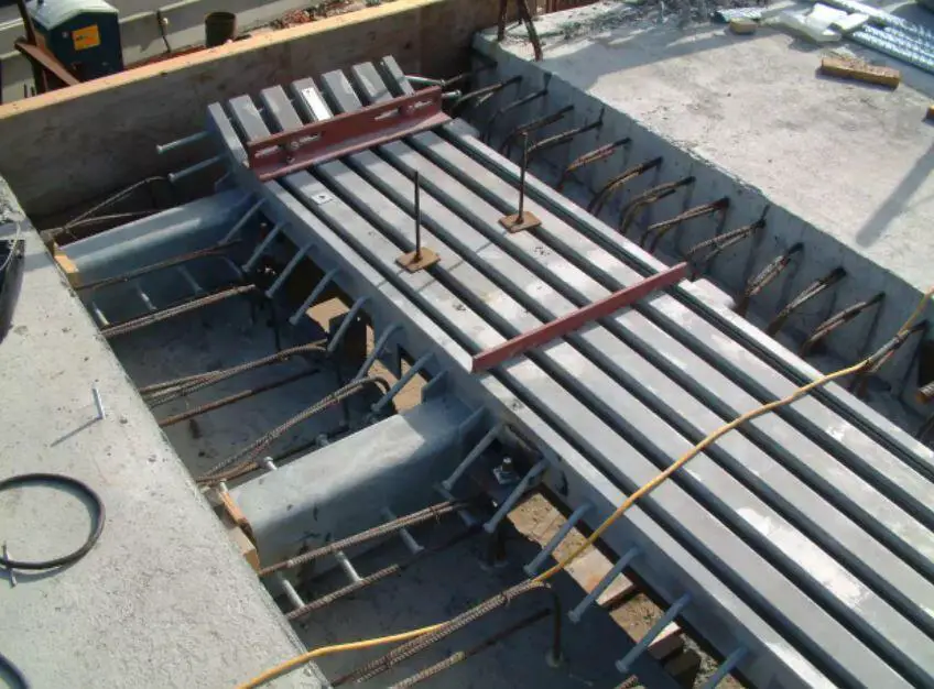
It’s also vital to describe any services that pass through expansion joints, and the need to accommodate services may well decide which of the aforementioned alternatives for detailing joints in verges is used. Certain couplings require specific clearances to any service ducts, which should be examined. Service ducts should be sufficiently spaced to allow for the flow of joint material around them as well as the placement of fixings between ducts.
Installation and maintenance
Faulty installation and inferior materials are two of the most common causes of expansion joint failure. When installing expansion joints, take care and follow the manufacturer’s instructions. Trained workers should be used, with special attention paid to identified weak spots such the interaction with the bridge deck waterproofing.
Bridge expansion joints should be inserted as late as feasible in the construction process to allow for shrinkage, creep, and settlement movements to occur before the expansion joint gap is filled.
Expansion joints should be built such that all wearable pieces can be replaced or reset quickly, ideally during off-peak hours. Joints should be inspected regularly to ensure that they are still functioning correctly and have not blocked up or leaked. Because of the dangers of allowing water to spill onto other bridge parts, any blocked drainage should be cleaned as soon as possible. To avoid the transmission of excessive stresses across the joint, and silting up of joints must be cleaned.
Reference
Reid I. L. K., Thayre P. A., Jenkins D. E., Broom R. A. and Grout D. J. (2008): Bridge Accessories in ICE Manual of Bridge Engineering (Institution of Civil Engineers) doi: 10.1680/mobe.34525.0553.






Having worked on bridges and done my part installing seal specs for these expansion joints I must commend you for this summary you have given to further explain the use of the design. A very interesting read anyone with a bit of interest and knowledge in this area will follow and understand. Thank you.
if length of Road bridge slab is 27 meters width 8m and depth is 0.60meter expansion joint is required or not