The purpose of a raft foundation is to spread the superstructure load across as much ground as possible and to provide the substructure some rigidity so that it can bridge over weaker or more compressible soil. The rigidity of a raft foundation also lowers differential settlement in soft clays. The principle of buoyancy is used in buoyancy rafts and basements (or box foundations) to lower the net weight on the soil. By so doing, the foundation’s total and differential settlements are therefore lowered. Bouyancy rafts are also called compensated foundations.
Buoyancy is produced by constructing a hollow substructure with a depth such that the weight of the soil excavated for it is equal to or slightly less than the combined weight of the superstructure and substructure.
Worked Example on Buoyancy Raft Foundation
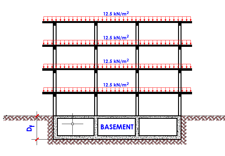
A four storey building is to be founded on soft clay which extends up to a depth of about 8m. The ultimate load per floor on the building is 12.5 kN/m2 while the proposed basement raft and the entire substructure is expected to weigh 25 kN/m2. By what depth should the basement be excavated such that there is no net pressure on the foundation? Take unit weight of clay as 18 kN/m2.
Solution
Total load from the superstructure = 12.5 x 4 = 50 kN/m2
Weight of substructure = 25 kN/m2
Total load transmitted to the foundation = 75 kN/m2
Effective pressure at the required depth = (18 x Df) = 18Df
For zero net pressure on the foundation;
18Df = 75
Depth of foundation Df = 75/18 = 4.167 m (say 4.2 m)
In the example shown above, excavation to a depth of 4.2 m for the basement relieves the soil at foundation level of a pressure of about 75.6 kN/m2. Since substructure itself weighs about 25 kN/m2, a loading of 50 kN/m2 can be placed on the basement before any additional loading causing settlement comes on to the soil at foundation level. A bearing pressure of 50 kN/m2 is roughly equivalent to the overall loading of a four-storey block of flats or offices.
Note that a reinforced concrete framed structure with brick and concrete external walls, lightweight concrete partition walls, and plastered finishing weighs about 12.5 kN/m2 each storey, which is a good rough estimate for calculating the weight of a multistory block of apartments. This figure includes a dead load of 100% and a maximum design live load of 60%.
As a result, a building of this height can theoretically be sustained on a basement founded in very soft and very compressible soil without settling.
If we assume that the building in the example studied above is placed on a mat foundation with dimensions of 20m x 15m, and the cohesion of the clay Cu is 30 kN/m2. We can determine the depth of the foundation for a factor of safety of 3 against bearing capacity failure. This will now be a case of partially compensated foundation.
The net ultimate bearing capacity of a mat foundation founded on clay is given by;
qnet(u) = qu – q = 5.14Cu[(1 + 0.195B/L)(1 + 0.4Df/B) (Das, 2008)
For a partially compensated foundation, the factor of safety is given by;
FS = qnet(u) / q = qnet(u) / (Q/A – γDf)
Hence, FS = 5.14Cu[(1 + 0.195B/L)(1 + 0.4Df/B) / (Q/A – γDf)
We can verify that Q/A = 75 kN/m2
B/L = 15/20 = 0.75
5.14Cu[(1 + 0.195B/L)(1 + 0.4Df/B) = [5.14(30) × [1 + (0.195 × 0.75)] × (1 + 0.4(Df/15)] = 176.751 + 4.719Df
(Q/A – γDf) = 75 – 18Df
Therefore;
3 = (176.751 + 4.719Df)/(75 – 18Df)
225 – 54Df = 176.751 + 4.719Df
48.249 = 58.719Df
On solving, Df = 0.821 m
Challenges in the Construction of Buoyancy Rafts
In practice, however, balancing the loads so that no additional pressure is applied to the soil is not easily achievable. Fluctuations in the water table alter the foundation’s buoyancy, and the intensity and distribution of live loading cannot be accurately predicted in most circumstances. Another aspect that contributes to the settlement of a buoyant foundation is the reconsolidation of swollen soil caused by the elimination of overburden pressure during substructure excavation.
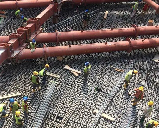
When the superstructure is built up, any swelling caused by elastic or long-term movements must be followed by reconsolidation when loading is replaced on the soil. For economy in the depth of foundation construction it is the usual practice to allow some net additional load to come on to the soil after the total of the dead load of the structure and its full live loading has been attained. The allowable intensity of pressure of this additional loading is determined by the maximum total and differential settlements which can be tolerated by the structure.
Both the ultimate and serviceability limit states must be considered in terms of limit states. Although a well designed buoyancy raft or basement should not experience bearing capacity failure, there is a danger of suffering an eventual limit condition owing to flotation of a fully or partially completed substructure.
An overestimation of soil density and ground-water table height could result in an underestimation of soil bearing pressure, resulting in excessive settling. Factors such as future groundwater table lowering or, conversely, future groundwater level rising due to site floods should be considered. In multi-cell buoyancy rafts, the weights of constructional materials and wall thicknesses (geometrical data) can be very critical.
Surcharges such as placing fill around a semi-buoyant substructure can be critical particularly if placed on one side only causing tilting. The latter can also be caused by variations in the position of imposed loading (spatial distribution), for example by stacked containers in a warehouse.
According to the EN 1997-1 (EC 7) regulation (Section 8, Retaining Structures), design values for the unit weight of water must take into account whether the water is fresh, saline, or chemically contaminated. Design parameters for water pressure and seepage forces are necessary to represent the limit state conditions with severe effects. The design values for limit states with less severe effects (often serviceability limit states) should represent the most unfavourable values that could occur in normal conditions.
Design of Buoyancy Rafts
It is very important to understand the differences between a basement and a buoyancy raft foundation. Although a basement functions as a type of buoyancy raft, it is not always constructed for that purpose. The main purpose of a basement is to provide the owner more room in the building, and the fact that it lowers the net bearing pressure due to the weight of the displaced soil may be purely coincidental. Basements are sometimes required for their function in decreasing net bearing stresses, and this is taken advantage of to create additional substructure floor area.
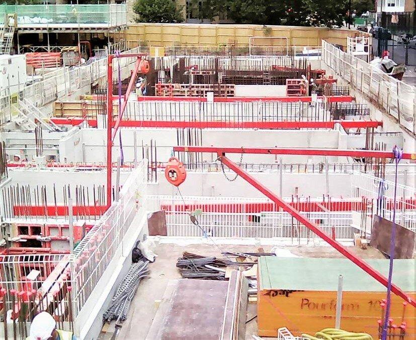
The genuine buoyancy raft, on the other hand, is a foundation that is built only to sustain the structure using the buoyancy provided by the displaced earth, with no consideration for other uses of the space. The raft is designed to be as light and rigid as possible to achieve this goal. Cellular or ‘egg-box’ architecture is the best way to combine lightness with rigidity.
This structural form limits the usefulness of the space within the substructure to accommodate any pipework or service ducts passing through holes in the walls of the cells. Because of the many problems inherent in the design and construction of buoyancy rafts, they have, in most cases, been supplanted by other expedients, mainly by various types of piling.
Maintaining buoyancy under ground conditions that need the cells to be waterproof might cause issues. Where the rafts are built in the shape of caissons, asphalt tanking or other membrane protection is not possible, and any water that seeps through fractures in the exterior walls or base shall be pumped out. Interior cell walls should have openings to allow water to drain to a sump where an automated pump can be placed.
In structures supported by buoyancy rafts, when gas is used for household heating or industrial activities, the cells should be sealed to prevent dangerous gas accumulations within the substructure.
Buoyancy rafts can be constructed either as open well caissons or in-situ in an open excavation. The caisson method is appropriate for soft clays because the soil within the cells can be grabbed as the raft sinks under its own weight. This approach, however, is inadequate for ground conditions when rigidity and weight are required to facilitate sinking through obstructions. When the soil is disturbed by grabbing reconsolidates under the superstructure loading, some settling should be expected where the caissons are terminated within the soft clay.
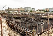
Construction in open excavations is appropriate for sites where the ground-water level can be maintained by pumping without risk of ‘boiling,’ and where soil heave at the excavation’s base is not extreme.




Love the infomation