8.7 C
New York
Monday, October 28, 2024
Home Blog Page 55

Punching Shear in Flat Slabs: A Design Example to Eurocode 2

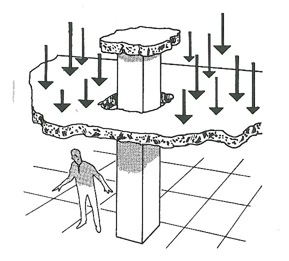
Punching shear failure occurs in a slab when the magnitude of a concentrated load (such as that from a column) exceeds the shear strength or resistance of the slab or the column punches through the slab. The failure plane is located at a certain distance from the perimeter of the column and has a funnel-shaped failure pattern. The design for punching shear resistance in flat slabs normally involves controlling the thickness of the slab or providing punching shear reinforcement.

Generically, punching is a three-dimensional, brittle failure mechanism leading to a truncated cone that separates from the slab. The shear crack develops from tangential flexural cracks and propagates into the direction of the compression zone near the column edge constricting the circumferential compression ring with increasing loads. Once the punching shear resistance is reached the shear crack intersects the uncracked compression ring leading to a sudden penetration of the column into the slab.
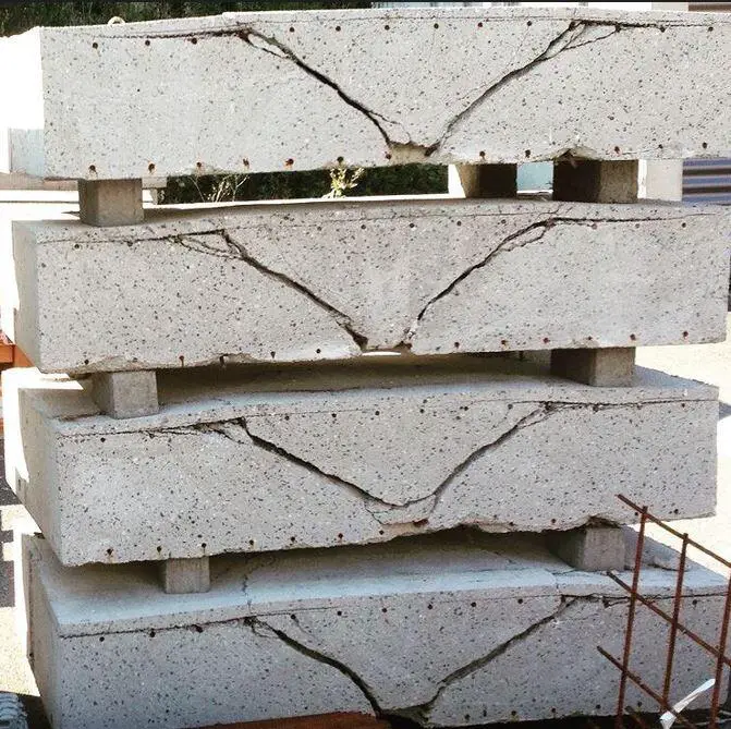
punching shear failure pattern
Typical failure pattern for punching shear

The recommendations found in BS EN 1992 (Eurocode 2) are usually followed when designing punched shear reinforcement. To assess whether punched shear reinforcement is necessary, the shear stress in the concrete is computed at the column face and at the fundamental control perimeter u1 (2d from the column face).

The position of the outside control perimeter where shear reinforcement is no longer needed (uout) is then determined if reinforcement is necessary. Shear studs are placed starting at 0.3d or 0.5d from the column face to within 1.5d of the outer control perimeter (uout), with intermediate studs spaced at 0.75d intervals.

The most cost-effective approach will often be a radial arrangement, with rails spaced either 30° or 45° apart. To meet this requirement, extra secondary rails are installed as necessary. The tangential spacing between studs is kept to within 1.5d for studs inside the basic control perimeter (u1) and 2d for studs outside the basic control perimeter.

The suggested values from BS EN 1992 can be used to design shear load VEd for internal, edge, and corner columns where lateral stability does not depend on frame action between slabs and columns and where neighbouring spans differ by less than 25%.

Design for punching shear should take moment transfer into account at the intersection of the column and slab. The design punching shear can be obtained for structures whose lateral stability is not dependent on the frame action between the slab and columns and where adjacent spans do not differ in length by more than 25% by increasing VEd by 1.15 for internal columns, 1.4 for edge columns, and 1.5 for corner columns.

image 7

Generally, the following checks should be carried out: 

  • Ensure that maximum punching shear stress is not exceeded, i.e. vEd < vRd,max at the column perimeter
  • Determine whether punching shear reinforcement is required, i.e. whether vEd > vRd,c at the basic perimeter, u1
  • Determine whether punching shear reinforcement is required, i.e. whether vEd > vRd,c at at successive perimeters to establish uout    = the length of the perimeter where vEd = vRd,c. Perimeters within 1.5 d from uout need to be reinforced.

Where required provide reinforcement such that vEd ≤ vRd,cs.

where

vEd  =    applied shear stress. The shear force used in the verification should be the effective force taking into account any bending moment transferred into the slab (see above)

vRd,max = design value of the maximum punching shear resistance, expressed as a stress
vRd,c = design value of punching shear resistance of a slab without punching shear reinforcement, expressed as a stress
vRd,cs    = design value of punching shear resistance of a slab with punching shear reinforcement, expressed as a stress.

vRd,cs = 0.75 vRd,c + 1.5 (d/sr)Asw fywd,ef (1/u1d)sin a

where:

Asw = area of shear reinforcement in one perimeter around the column (subject to Asw,min)
sr    = radial spacing of perimeters of shear reinforcement
fywd,ef = effective design strength of reinforcement (250 + 0.25d) ≤ fywd
d    = mean effective depth in the two orthogonal directions (in mm)
u1   = basic control perimeter at 2from the loaded area
sin a = 1.0 for vertical shear reinforcement

Where required each perimeter should have
Asw = (vEd – 0.75 vRd,c)sr u1/(1.5 fywd,ef)

The punching shear resistance of a slab should be assessed for the basic control section (see Figure 6.12). The design punching shear resistance [MPa] may be calculated as follows:

vRd,c = CRd,c k (100 ρl fck)1/3 + k1 σcp   ≥ (vmin + k1 σcp)

where:
fck is the characteristic compressive strength of concrete, see Table 3.1
k= 1 + √200/d   ≤ 2.0
where d is the effective depth, in [mm]ρl= (ρlyρlz)1/2 ≤ 2%
ρlyρlz are longitudinal reinforcement ratios in y- and z- directions respectively. Their values should be calculated as mean values taking into account a slab width equal to column width plus 3d each side σcp= (σcy + σcz)/2,
where σcyσcz are the normal concrete stresses in the critical section in y- and z- directions (in [MPa], positive if compression):
σcy = NEd,y / Acy and σcy = NEd,z / Acz
NEd,yNEd,y are the longitudinal forces across the full bay for internal columns and the longitudinal force across the control section for edge columns. The force may be from a load or prestressing action.
AcyAcz are the areas of concrete according to the definition of NEd,yNEd,y respectively
CRd,c is a Nationally Determined Parameter, see § 6.4.4 (1)
vminis a Nationally Determined Parameter, see § 6.4.4 (1), or (6.3N) for the calculation of vmin following the Eurocode recommendation
k1 is a Nationally Determined Parameter, see § 6.4.4 (1).

Punching Shear Design Example

For the flat slab with the general arrangement as shown below, let us design the punching shear for column B1 given the following design information;

Ultimate axial force on column VEd = 400 kN
Thickness of slab = 250 mm
Dimension of column = 450 x 230 mm
Reinforcement of slab in the longer direction = H16@150mm (As,prov = 1340 mm2)
Reinforcement of slab in the shorter direction = H16@175mm (As,prov = 1149 mm2)
Grade of concrete = C30
Yield strength of reinforcement = 500 Mpa
Concrete cover to slab = 25mm

column%2Bstrips

Solution

Effective depth of slab in y-direction dy = 250 – 25 – (16/2) = 217 mm
Effective depth of slab in x-direction dx = 250 – 25 – 16 = 209 mm

ρly = (1340) / (1000 × 217) = 0.00617 (reinforcement ratio)
ρlx = (1149) / (1000 × 209) = 0.00549 (reinforcement ratio)

(a) Check shear at the perimeter of the column

VEd = β VEd/(u0d) < VRd,max

punching%2Blocations

From figure 6.21N of EN 1992-1-1;
β = 1.40
d = (217 + 209)/2 = 213 mm

u0 = c2 + 3d < c2 + 2c1 For edge columns (clause 6.4.5(3))

PUNCHING%2BAGAIN

u0 = 230 + (3 × 213) <  (230 + 2 × 450)
u0 = 869 mm
VEd = 1.40 × 400 × 1000/(869 × 213) = 3.025 MPa
VRd,max = 0.5 ν fcd
= 0.5 × 0.6(1 – fck/250) × αcc fckm
= 0.5 × 0.6(1 – 30/250) × 1.0 × (30 /1.5) = 5.28 MPa
VEd < VRd,max …OK


(b) Check shear at u1, the basic control perimeter
VEd = β VEd/(u1d) < VRd,c

β,VEd as before
u1 = c2 + 2c1 + π × 2d
u= 230 + (2 × 450) + (π × 2 × 213) = 2468 mm

VEd = 1.4 × 400 × 1000/(2468 × 213) = 1.065 MPa
VRd,c = 0.12 k(100 ρl fck)1/3

k = 1 + (200/d)1/2 = 1 + (200/213)1/2 = 1.969

ρl = (ρlyρlx)1/2 = (0.00617 × 0.00549)1/2 = 0.00582

VRd,c = 0.12 × 1.969(100 × 0.00582 × 30)1/3 = 0.613 MPa

VEd > VRd,c ?
1.065 MPa > 0.613 MPa … Therefore punching shear reinforcement required

NA check:
VEd ≤ 2.0VRd,c at basic control perimeter
1.06 MPa ≤ 2 × 0.613 MPa = 1.226 MPa – OK

(c) Perimeter at which punching shear no longer required
uout = β VEd/(dVRd,c)
= 1.4 × 400 × 1000/(213 × 0.613) = 4289 mm

Rearrange: uout = c2 + 2c1 + π rout
rout = (uout – (c2 + 2c1))/π
rout = (4289 – 1130)/π = 1005 mm

Position of outer perimeter of reinforcement from column face:
r = 1005 – 1.5 × 213 = 686 mm

Maximum radial spacing of reinforcement:
sr,max = 0.75 × 213 = 159.75 mm, say 150 mm

(d) Area of reinforcement
Asw ≥ (VEd – 0.75VRd,c)sru1/(1.5fywd,ef)
fywd,ef = (250 + 0.25d) = 303 MPa

Asw ≥ (1.065  – 0.75 × 0.613) × 150 × 2468/(1.5 × 303)
≥ 492 mm2 per perimeter

Provide 7H10 (Asprov = 549 mm2 per perimeter)

Within the u1 perimeter the link spacing around a perimeter,
st ≤ 1.5d = 1.5 × 213 = 319.5 mm

Outside the u1 perimeter the link spacing around a perimeter,
st ≤ 2d = 426 mm
Use say st,max = 300 mm

Minimum area of a link leg:
Asw,min ≥ [0.053 sr st sqrt(fck)] /fyk = (0.053 ×  150 ×  300 ×  √30) / 500
≥ 26 mm2

Use H10s (78.5 mm2) and 7 per perimeter.
@ 300 mm tangential spacing and @150 mm radial spacing
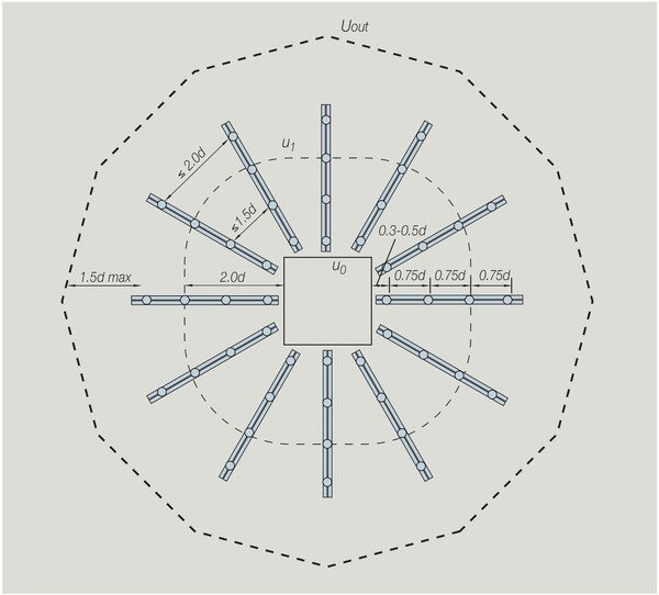
arrangement od punching shear reinforcement

Thank you for visiting Structville today and God bless you.


Design of Longitudinal Reinforcement in Piles

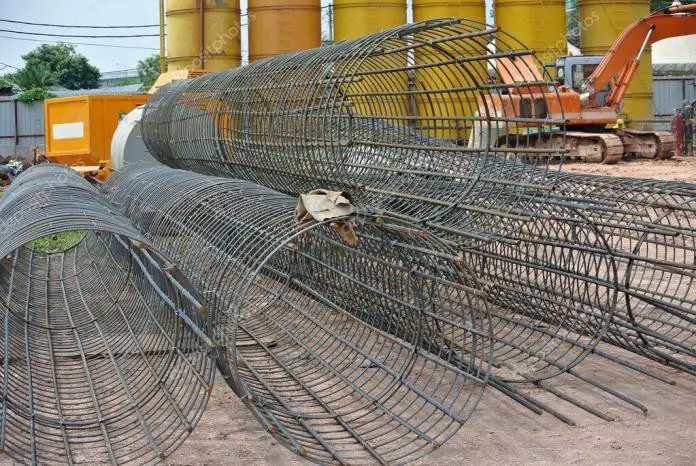
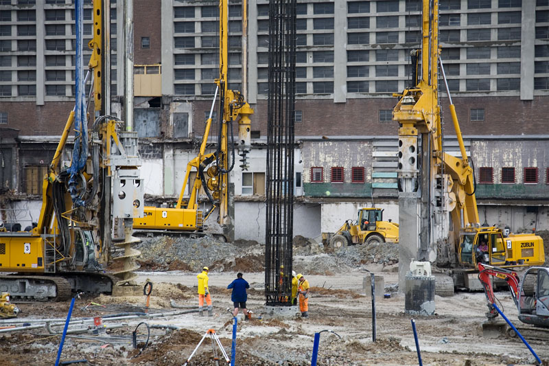
Precast piles are designed to withstand stresses caused during their installation, and the load from their service life. Bored piles on the other hand and usually designed to withstand the stresses they are subjected to while supporting the superstructure and other actions as may be anticipated. These could be earthquake forces, other lateral loads, or uplift forces.

Furthermore, piles of all types may be subjected to bending stresses caused by eccentric loading, either as a designed loading condition or as a result of the pile heads deviating from their intended positions. This post is aimed at exploring the methods of providing longitudinal reinforcement for bored piles, and the minimum reinforcement acceptable.

Buckling of piles that are embedded in a firm soil cannot occur unless they are loaded beyond their capacity, hence there is no need to design such piles as slender columns. However, when the piles are projecting above the ground level, then there is a need to consider such behaviour.

Also, when a pile passes through a very weak stratum of clay with low lateral stiffness, and is founded on a hard stratum, then buckling becomes a problem. If the undrained shear strength of the soil cu is less than 10 kN/m2, then there is a need to check for buckling.

Read Also….

Structural design of pile caps using strut and tie model
Design of piles in sand: Case Study of Lekki Pennisula Lagos

Reinforcement Requirement and Detailing of Bored Piles
Section 9.8.5 of EN 1992-1-1:2004 deals with the detailing requirements of bored piles. Clause 9.8.5(3) said that bored piles with a diameter not exceeding 600mm should be provided with a minimum longitudinal reinforcement of As,bpmin. The recommended minimum longitudinal reinforcement of cast-in-place bored piles is given in Table 9.6N of EN 1992-1-1:2004 and reproduced below;

Minimum%2Blongitudinal%2Breinforcement%2Bof%2Bbore%2Bpiles

The requirement further states that the minimum diameter for the longitudinal bars should not be less than 16 mm. Piles should have at least 6 longitudinal bars and the clear distance between bars should not exceed 200 mm measured along the periphery of the pile.

However, these rules differ from the requirements of BS EN 1536:2010 + A1(2015) which states that for reinforced piles, the minimum longitudinal reinforcement shall be 4 bars of 12 mm diameter, and the spacing should be maximised to allow proper flow of concrete but should not exceed 400 mm.

pile%2Breinforcement

According to clause 6.9.2.1 of BS 8004:2015, the design compressive resistance (Rc,d) of the reinforced length of a cast-in-place pile is given by;

Rc,d = fcdAc,d + fydAs,d

Where;
fcd = design compressive strength of the concrete = (αcc × fck)/(kf × γc)
αcc = factor taking into account the long-term reduction in strength of concrete (take as 0.85)
fck =  characteristic compressive strength of concrete
kf = A multiplier to the partial factor of concrete for concrete piles cast-in-place without permanent casing (value is 1.1)
γc = partial factor for concrete
Ac,d = cross-sectional area of pile

fyd = design yield strength of steel = (fyk / γs)
fyk =  characteristic yield strength of steel
γc = partial factor for steel
As,d = Area of steel required

The links, hoops, or helical reinforcements are required to be designed in accordance with EC2, but the diameter of the bar should not be less than 6 mm, or one-quarter of the maximum diameter of the longitudinal bars. The maximum reinforcement should be taken as 4% of the cross-sectional area.

According to clause 6.9.2.6, of BS 8004:2015, depending on the magnitude of loading, a cast-in-situ pile may be reinforced over its whole length, over part of its length, or merely provided with short splice bars at the top for bonding into the pile cap. If the concrete pile is expected to resist tensile forces, the reinforcement should be extended down to the full length.

Solved Example

A 500 mm diameter pile has a safe working load of 540 kN and the actual load it is being subjected to is 485 kN. Provide suitable reinforcement for the pile if it is a frictional pile embedded in dense sand and the characteristic strength of concrete and steel are 30 MPa and 500 MPa respectively.

Solution

Rc,d = fcdAc,d + fydAs,d

Ac,d = πd2/4 = (π × 5002)/4 = 196349.54 mm2
fcd = (0.85 × 30)/(1.1 × 1.5) = 15.45 N/mm2
fyd =  (500 / 1.15) = 434.782 N/mm2
Rc,d = 540000 N

540000  = (196349.54 × 15.45) + 434.782 As,d
A little consideration will show that solving for As,d will give us a negative value, therefore provide minimum reinforcement

Since Ac < 0.5 m2;
As,bpmin = 0.005 × Ac,d = 0.005 × 196349.54 = 982 mm2
Provide 6H16mm (As,prov = 1206 mm2)

567

Following strictly the detailing requirements of EC 2, a clear distance of 200 mm has not been exceeded.

Provide H10mm @ 300mm pitch spiral links

Read Also;

How to Apply Load Model 1 on Highway Bridges

Analysis of Trusses Using Direct Stiffness Method

Minimum Concrete covers (clause 7.6.4 BS 8004:2015)
60mm for piles with diameter > 600mm
50mm for piles with diameter ≤ 600 mm

The cover can be increased to 75mm under special circumstances.

Thank you for visiting Structville Today… God bless you


Question of the Day (04/06/2018)

Structville daily questions
From now henceforth, Structville will be publishing daily questions on different aspects of civil engineering. You are expected to enter your response in the comment section. At the end of every week, exceptional participants will stand a chance to win some gifts. This exercise is open to participants all over the world. Happy new month to you all.


Today’s Question
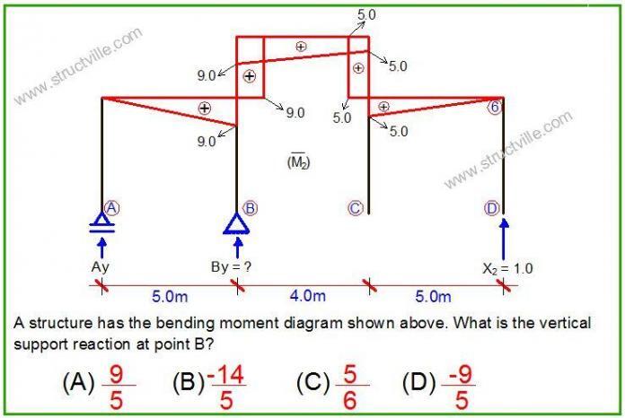
What is the vertical support reaction at point B of the frame?

Thank you for participating in exercise today, remember to enter your answer in the comment section. The main aim of this exercise to stimulate knowledge of structural analysis on the internet in a fun and exciting way. We are always happy to hear from you, so kindly let us know how you feel about Structville.

E-mail: info@structville.com
WhatsApp: +2347053638996

You can also visit Structville Research for downloads of civil engineering materials.

STRUCTVILLE REINFORCED CONCRETE DESIGN MANUAL
We have this very affordable design manual available…

final%2Bfront%2Bcover

Do you want to preview the book, click PREVIEW
To download full textbook, click HERE

Structville Online Professional Training and Webinars

Structville Integrated Services in our commitment to human capacity development, has decided to launch series of online lectures and webinars for civil engineering professionals and students. We wish to specify that this program is by choice, and there must be interest to participate before you can embark on this journey. We called it a journey because the whole program will be carried out online, and you should have enough data to download the videos, PowerPoint presentations, and papers that would circulated during the program. This is the only way you can maximize your benefits.

The program will last for 3 weeks (Friday 15/06/2018 to Friday 06/07/2018), and the arrangement is prepared in such a way that you will be able to download the resource materials and follow the discussions even if you are not online at a period that a particular session will be held. A time table would be published for the program, and it is advisable that you plan ahead and make yourself available so as to enable you ask questions. The promise is that all questions would be adequately attended to. We have mobilised distinguished resource persons from civil engineering profession all over the world to participate in the different sessions and give us the best ideas/interactions.

The online training has been divided into two categories;
– Category 1 –  ₦5,000
– Category 2 – ₦10,000

The topics to be treated are as follows;

Category 1 (₦5,000 / $15.00)
(1) Basis of Structural Design (PowerPoint Presentations, Papers, Case Studies, Discussions)

(2) Structural Analysis and Design of Office Complex Using Staad Pro Software (Video Tutorials, PowerPoint Presentations, Lecture notes)

(3) Structural Analysis and Design of Industrial Steel Structure Using Staad Pro Software (Video Tutorials, Powerpoint Presentations, Lecture Notes)

(4) Structural Analysis and Design of Beam and Raft Foundation Using Orion Software (Video Tutorials, Powerpoint Presentations, Lecture Notes)

(5) Matrix Methods of Structural Analysis – Force Method, Stiffness Method, and Finite Element Analysis (Lecture notes, Video Tutorials, Solved Examples)

(6) Life as a Civil Engineer and Challenges of the Industry (Power Point Presentations, Discussions, and Case Studies)

Category 2 (₦10,000 / $30.00)
(1) Leadership, Intelligence, Investment, and Capacity Building in Civil Engineering Profession (Papers, PowerPoint, Case Studies, Videos, Foreign Interactions)

(2) Basis of Structural Design (PowerPoint Presentations, Papers, Case Studies, Discussions)

(3) Limit State and Structural Reliability Theory (Papers, Lecture notes, and discussions)

(4) Structural Analysis and Design of Office Complex Using Staad Pro Software (Video Tutorials, PowerPoint Presentations, Lecture notes)

(5) Structural Analysis and Design of Industrial Steel Structure Using Staad Pro Software (Video Tutorials, Powerpoint Presentations, Lecture Notes)

(6) Structural Analysis and Design of Beam and Raft Foundation Using Orion Software (Video Tutorials, Powerpoint Presentations, Lecture Notes)

(7) Advanced Modelling and Analysis on Staad Pro – Bridges, Box Culverts, and Staircases (Video tutorials, PowerPoints,  and Lectures)

 
(8) Advances in Civil Engineering Materials (Videos, PowerPoint, Case studies, and Papers)
 
Followers of Structville blog can testify on our commitment to quality and excellence, and this webinar and online training will be another testimony. Just like I stated earlier, the idea is for you to have adequate data bundle beacause there will be excess downloads to make (especially for the videos). If you cannot afford it, do not bother yourself so much, but you would really miss. Structville’s vision and mission is very accommodating.
REGISTRATION WOULD RUN FROM MONDAY 04/06/2018 TO THURSDAY 14/06/2018
To participate in this program, and for further inquiries, all you need is to send an e-mail and/or whatsapp message to;
E-mail: ubani@structville.com
WhatsApp: +2347053638996

To register expressly click HERE


Solution to Questions of the Week and Winners (03/06/2018)

67777

Last week, we presented some questions on structural mechanics, and we wish to publish the answers and congratulate the winners.


Monday (28/05/2018)
We were required to obtain the column moment of the frame loaded as shown below.

challenge%2B1

We can simply obtain this by summing up the moment at point B due to the externally applied;

Let anticlockwise moment be negative;
MBBelow = (-2 × 2) + (6 × 2.5) = 11 kNm
It is as simple as that. So the correct option A.


Those that got the answers correct are;

  • Thaddeus Odinakachi Ekwughaa
  • Ogundare Folahanmi
  • Guiseppe Martino Erbi
  • Ogungbire Adedolapo
  • Romel Batongbakal
  • Ajit umar Mohanty
  • Abdul Basheer
  • Shrujal Barvaliya
  • Ovie Agbaga
  • Peter O.
A big congratulations to you all for contributing to knowledge and undersyanding.
Wednesday (30/05/2018)
We were required to plot the bending moment of the frame shown below due to the applied unit load;
question%2Bof%2Bthe%2Bday%2B2
The frame is statically determinate and stable.
Therefore the moment at point C due to the load at point C is given by;

MC = (1 × 3.0) = 3.0 kNm
This moment of 3 kNm acts as a couple from point C and goes all the way down to point B.

The moment at point A is given by;
MA = (1 × 11) = 11.0 kNm

Therefore, the correct option is A.

Those that got the answer correct are;

  • Guiseppe Martino Erbi
  • Ogungbire Adedolapo
  • Romel Sevilla Batongbakal
  • Feyisetan Kwasima
  • Ajit Kumar Mohanty
  • Charles
  • Thaddeus Odinakachi Ekwughaa
  • Palo Tuleja
  • Shrujal Barvaliya
  • Shah Ezud Din
  • Ovie Agbaga
  • Peter O.
A big congratulations to you all.

Friday (01/06/2018)
We are to calculate the deflection of the structure by considering the main moment diagram and unit state diagram.
QUESTION%2BOF%2BTHE%2BDAY%2B3
Solution;
Deflection = 1/4 × 6 × 2× 2 = 6/EI metres
Those that got the answers correct are;

  • Ogungbire Adedolapo
  • Ogunleye Emmanuel
  • Mezie Ethelbert
  • Giuseppe Martino Erbi
  • Romel Sevilla Batongbakal
  • Ovie Agbaga
Winners
From the rules of the competition, the winners for the week are as follows;
  • Ogungbire Adedolapo
  • Giuseppe Martino Erbi
  • Romel Sevilla Batongbakal
  • Ovie Agbaga

We say a big congratulations to you all, and we sincerely appreciate your valuable contributions. Kindly forward your e-mail addresses for some special gifts. Our sincere appreciation also goes out to those who participated on various social media platforms. God bless you all.


Crack Control of R.C. Slabs Using Simplified Rules

Cracking is the partial or complete separation of a section into two or more parts as a result of fracture. In concrete sections, cracking occurs when the tensile stress exceeds the tensile strength of the concrete. Due to the inherent weakness of concrete in tension, it is bound to crack easily and more often than not, steel reinforcements are used for crack control.

Cracking can occur in concrete in a plastic or hardened state. Autogenous shrinkage, differential settlement, drying shrinkage, thermal stresses, chemical reactions, imposed restraints, corrosion of reinforcement, poor construction techniques, construction overloads, errors in design and detailing, and externally applied loads are all potential causes of cracking in concrete.

Cracking is considered a serviceability limit state problem in reinforced concrete design. Reinforced concrete slabs are prone to cracking because they are predominantly subjected to flexural stresses. Therefore, crack control using reinforcements is very important in the design of reinforced concrete slabs. The serviceability limit states covered by Eurocode 2 are;

– Stress limitation (section 7.2)
– crack control (section 7.3) and
deflection control (section 7.4)

According to clause 7.3.1 of EN 1992-1-1:2004, the general considerations in the control of cracking in a building are as follows;

  • (1)P Cracking shall be limited to an extent that will not impair the proper functioning or durability of the structure or cause its appearance to be unacceptable.
  • (2) Cracking is normal in reinforced concrete structures subject to bending, shear, torsion or tension resulting from either direct loading or restraint or imposed deformations.
  • (3) Cracks may also arise from other causes such as plastic shrinkage or expansive chemical reactions within the hardened concrete. Such cracks may be unacceptably large but their avoidance and control lie outside the scope of this Section.
  • (4) Cracks may be permitted to form without any attempt to control their width, provided they do not impair the functioning of the structure.
  • (5) A limiting calculated crack width, wmax, taking into account the proposed function and nature of the structure and the costs of limiting cracking, should be established.

In Eurocode 2 cracking is controlled in the following ways:

Minimum areas of reinforcement Cl 7.3.2 & Exp (7.1)
• Limiting crack widths.

wkmax is determined from Table 7.1N (in the UK from Table NA.4)

These limits can be met by either:
– ‘deemed to satisfy’ rules (Cl. 7.3.3)
– direct calculation (Cl. 7.3.4) – design crack width is wk
Note: slabs ≤ 200 mm depth are okay if As,min is provided.

A little consideration will however show that the deemed to satisfy rules are more handy and applicable for all design purposes. A solved example on application of deemed to satisfy rules is presented in this post.

Worked Example on the Crack Control of RC Slab

Let us consider a simply supported slab in a proposed office building. The thickness of the slab is 150 mm, and the dead load on the slab gk = 5.6 kN/m2, and the live load qk is 3 kN/m2. The area of steel required is 698 mm2/m, and the area of steel provided is 753 mm2/m. (T12@150mm). Verify if the slab meets the cracking requirement according to Eurocode 2 limiting the crack width to 0.3mm.

Solution

In order to use Tables 7.2N or 7.3N of EC2, we need to determine the service stress in the bars by;

Service stress/Ultimate stress = [(Gk + ψ2Qk,1)/(γGGk + γQQk,1)] × (1/δ)
ψ2 = 0.3 (see the table below for combination factors)

Actionψ0ψ1ψ2
Category A: domestic, residential 0.70.50.3
Category B: office area0.70.50.3
Category C: congregation areas0.70.50.6
Category D: shopping area0.70.70.6
Category E: storage areas1.00.90.8
Category F: traffic area, ≤ 30 kN0.70.70.6
Category G: office area, 30 – 160 kN0.70.50.3
Category H: roofs00
Snow load: H ≤ 1000m a.s.l.0.50.20
Wind loads on buildings0.50.20

γG = 1.35
δ = 1.0
Service stress/Ultimate stress = (5.6 + 0.3 × 3)/(1.35 × 5.6 + 1.5 × 3) = 0.5389

The stress in the reinforcement under quasi-permanent loading is given by;
σs = 0.5389 × 0.87fyk × (As,req / As,prov) = 0.5389 × 0.87 × 460 × (698/753) = 199.94 Mpa

From Tables 7.2 and 7.3 of EC2;

crack%2Bcontrol

From table, maximum bar size = 25 mm
Maximum bar spacing = 250 mm

Therefore the size of the reinforcement spacing of the rebars is sufficient to limit the cracking of the slab to 0.3 mm.

Thank you for visiting Structville today.


Question of the Day (01/06/2018)

QUESTION%2BOF%2BTHE%2BDAY%2B3


Structville daily questions
From now henceforth, Structville will be publishing daily questions on different aspects of civil engineering. You are expected to enter your response in the comment section. At the end of every week, exceptional participants will stand a chance to win some gifts. This exercise is open to participants all over the world. Happy new month to you all.


Today’s Question
What is the deflection at point 2 of a structure if diagram (a) is the bending moment due to externally applied load, and (b) is the bending moment due to vertically applied virtual load at point 2? (The main bending moment diagram is obtained from equation of the form, wl2/2)

Thank you for participating in exercise today, remember to enter your answer in the comment section. The main aim of this exercise to stimulate knowledge of structural analysis on the internet in a fun and exciting way. We are always happy to hear from you, so kindly let us know how you feel about Structville.

E-mail: info@structville.com
WhatsApp: +2347053638996

You can also visit Structville Research for downloads of civil engineering materials.

STRUCTVILLE REINFORCED CONCRETE DESIGN MANUAL
We have this very affordable design manual available…

final%2Bfront%2Bcover

Do you want to preview the book, click PREVIEW
To download full textbook, click HERE

Question of the Day (30/05/2018)

question%2Bof%2Bthe%2Bday%2B2


Structville daily questions
From now henceforth, Structville will be publishing daily questions on different aspects of civil engineering. You are expected to enter your response in the comment section. At the end of every week, exceptional participants will stand a chance to win some gifts. This exercise is open to participants all over the world.


Today’s Question
For the  frame loaded as shown above, which of the options is the most likely bending moment diagram considering linear elastic response.

Thank you for participating in exercise today, remember to enter your answer in the comment section. The main aim of this exercise to stimulate knowledge of structural analysis on the internet in a fun and exciting way. We are always happy to hear from you, so kindly let us know how you feel about Structville.

E-mail: info@structville.com
WhatsApp: +2347053638996

You can also visit Structville Research for downloads of civil engineering materials.

STRUCTVILLE REINFORCED CONCRETE DESIGN MANUAL
We have this very affordable design manual available…

final%2Bfront%2Bcover

Do you want to preview the book, click PREVIEW
To download full textbook, click HERE

Problems of Civil Engineering Consultancy in Nigeria

The wealth creation cycle in construction industry revolves around the political climate, economy, government policies, availability of resources, technology, and skilled manpower. Thousands of engineering graduates leave school in Nigeria each year, and the job opportunities are getting leaner by the day. If I may say, this trend is worse in structural engineering consultancy sector in Nigeria.


In Nigeria currently, construction and real estate companies are recruiting more civil engineering graduates than any other sector. The consultancy sector has been stagnant in terms of job creation recently.  There are a lot of explanations to this trend, and the idea is to keep fresh graduates abreast of the current position of the industry.

Current challenges of the consultancy sector;

(1) Inadequate Regulation
In the classroom, there appears to be a scale of fees for professionals in a building project, but out there in the field, there seems to be no professional standard. For instance in the structural design of buildings, it is not very clear whether we charge on the basis of number of floors, or area of  the building, or a percentage of the estimated total cost of the building. It appears every organisation has its own way of charging for designs in order to balance their book.

Also fresh graduates and students who have acquired design skills do not hesitate in collecting design jobs directly from architects and clients. With all these challenges of no basic control, the consultancy sector has become a haven of negotiation and bargaining power, instead of professional standard. However, it is important to point out that a few Grade ‘A’ consultancy firms still maintain their standards, and those who need them knows where to find them.

(2) Availability of Design Softwares
The availability of commercial softwares have improved speed, accuracy, and output of many consultancy firms. The negative aspect of it is that the demand for man power has significantly reduced. If a consultancy firm lands one design job per month, then they can comfortably make do with just one design engineer depending on the complexity of the jobs. With these softwares guaranteeing speed in output, engineers spend less time in generating working drawings and documents, thereby making organisations realise that they need fewer hands.


(3) In-house Designs
In order to save cost, most construction and real estate companies have resolved to carrying out their designs in-house by employing the services of a structural engineer. As a result of this, fewer jobs get to real consultancy firms, and the sector continues to suffer.

(4) Crowded Industry
The built environment sector in Nigeria is currently crowded with a lot of professionals offering the same services. In our society today, civil engineers are building, builders are building, architects are building, masons are building, and even quantity surveyors are building. In this case, anyone can easily obtain their working drawings from any source at the cheapest rate, work hard on obtaining COREN stamp, and all the way the building goes. If this issue is notaddressed, the consultancy sector will continue to suffer. This has led to many certified professionals into mediocrity in the bid to survive.

civil

(5) Lack of research and creativity
The conventional system of building in Nigeria has remained largely the same over a long period of time. The advances that have been made in materials science and technology rarely reflects in the construction projects executed in Nigeria. Innovation and creativity is what drives any industry, and if there are no new trends, we will remain stuck where we are. Engineers are encouraged to continue exploits in the areas of adaptation, research, sustainability, cost reduction, and improved technology. This is one of the ways consultancy can be revitalised.

(6) Insignificant Public Private Partnership (PPP)
In Nigeria, the construction industry is still largely financed by public funds, apart from the real estate sector that can be said to be shared equally. So for the industry to thrive, there is need for more public Private Partnership (PPP) initiatives to drive the industry forward. It is obvious the government cannot no longer do it alone due to huge capital requirements. This will have significant impact in the consultancy sector.

Eko Atlantic Nigeria1

Finally, I wish to encourage engineers to keep up the acts of hard work and professionalism in all their endeavours. Positive entrepreneurship geared towards service to humanity, research, development, sustainability, and enterprise is highly encouraged. Footprints on the sands of time are not made by sitting down. Nigeria is ours… God bless.


On the Bearing Capacity of Shallow Foundations

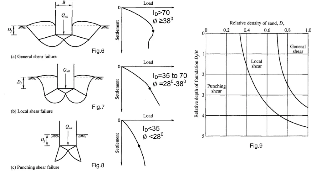
Bearing capacity is the maximum load a soil profile can withstand before undergoing excessive deformation and shear failure. It is the most popular and perhaps the most important information needed for the design of shallow foundations. The allowable bearing capacity of soil is used for the proper sizing of shallow foundations so that the load from the superstructure will not exceed the strength of the soil or lead to an excessive settlement.

If a load is applied gradually to a foundation, the settlement will increase. At a certain point when the load equals the bearing capacity of the soil, sudden failure of the soil supporting the foundation will take place. This sudden failure in which the failure surface will extend into the ground is known as ‘general shear failure‘.

When the soil supporting the foundation is of sand or clay soil of medium compaction, the failure surface of the soil will gradually extend outward from the foundation. When the applied load reaches the bearing capacity of the soil, the foundation movement will be accompanied by sudden jerks, and considerable movement will be required before the failure surface extends into the ground. This is generally referred to as ‘local shear failure‘, and the peak value of the load is not realised in this type of failure.

If the foundation is founded on loose soil, the failure surface will not extend into the ground surface. The load-settlement plot of this interaction will be steep and practically linear. Such failure is referred to as ‘punching shear failure‘.

types of foundation failure
Different types of bearing capacity failure

The methods of determining the ultimate bearing capacity of soils are;

  • General shear failure theory of Terzaghi
  • Theoretical solutions presented by Meyerhof, Hansen, and Vesic
  • Correlations from in-situ tests such as PLT, SPT, and CPT

Information needed for the evaluation of the bearing capacity of soil is obtained from site investigation. Laboratory study of undisturbed samples or in-situ soil tests can be done in order to obtain the shear strength parameters needed for the evaluation of the bearing capacity. Several correlations exist for relating in-situ soil properties from cone penetration test to bearing capacity of the soil.

Soil investigation is therefore one of the most important activities that must be carried out before the commencement of any construction project. In the soil test report, the geotechnical engineer is expected to state the strength of the soil at different layers, and ultimately recommend a suitable foundation. Some of the parameters used in describing the strength of a soil formation for the purposes of estimating the soil bearing capacity are the cohesion and the angle of internal friction of the soil.

In this article, we are going to present an example of how to determine the bearing capacity of soil using the general bearing capacity equation.

Background to the bearing capacity of shallow foundations

Terzaghi in 1943 extended the plastic failure theory of Prandtl to evaluate the bearing capacity for shallow strip footings. After the development of Terzaghi’s bearing capacity equation, several scholars such as Meyerhof (1951 and 1963), Vesic (1973), Hansen (1970), etc worked on this area and refined the solution to what is known as the general bearing capacity equation. This modification allowed for depth factor, shape factor, and inclination factors.

The modified general ultimate bearing capacity equation can be written as;

qu = c’FcsFcdFciNc + qFqsFqdFqiNq + 0.5FγsFγdFγiγBNγ

Where;
Fcs, Fqs, Fγs are shape factors which account for the shearing resistance developed along the surface in soil above the base of the footing
Fcd, Fqd, Fγd are depth factors to determine the bearing capacity of rectangular and circular footings
Fci, Fqi, Fγi are inclination factors to determine the bearing capacity of a footing on which the direction of load application is inclined at a certain angle to the vertical

Solved Example on the determination of bearing capacity

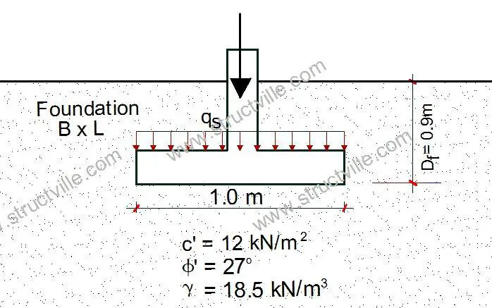
Let us determine the bearing capacity of a simple pad foundation with the following data;

Bearing capacity of shallow foundations

Depth of foundation Df = 0.9 m
Width of foundation B = 1.0 m
Effective cohesion of soil c’ = 12 kN/m2
Angle of internal friction φ’ = 27°
Unit weight of soil = 18.5 kN/m3

The water table is about 9 m below the surface

From table, we can determine the bearing capacity factors;

rtty
Bearing capacity factors culled from Das and Sobhan (2012)

Angle of internal friction φ’ = 27°
Nc = 23.94; Nq = 13.20; Nγ = 14.47

Fcs = 1 + (B/L)(Nq /Nc) = 1 + (1.0/1.0)(13.2/23.94) = 1.551
Fqs = 1 + (B/L)tanφ’  = 1 + (1.0/1.0)tan 27 = 1.509
Fγs = 1 + 0.4(B/L)  = 1 + 0.4(1.0/1.0) = 1.4

Fcd = 1 + 0.4(Df/B)  = 1 + 0.4(0.9/1.0) = 1.36
Fqd = 1 + 2tanφ'(1 – sin φ’)2(Df/B)  = 1 + 2tan27(1 – sin 27)2 (0.9/1.0) = 1.273
Fγd = 1.0

Since we are assuming vertical loads, take Fci = Fqi = Fγi = 1.0

q = (18.5 kN/m3 × 0.9 m) = 16.65 kN/m2

qu = c’FcsFcdFciNc + qFqsFqdFqiNq + 0.5FγsFγdFγiγBNγ
qu = (12 × 23.94 × 1.551 × 1.36 × 1.0) + (16.65 × 1.509 × 1.273 × 1.0 × 13.20) + (0.5 × 1.4 × 1.0 × 1.0 × 18.5 × 1.0 × 14.47) = 1215.55 kN/m2

Using a factor of safety (FOS) of 3.0
qallowable = qu /FOS = 1215.55/3.0 = 405.183 kN/m2

So with this, the allowable bearing capacity of the soil can be stated as 405 kN/m2