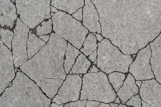
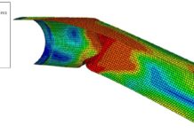
Cracking is the partial or complete separation of a section into two or more parts as a result of fracture. In concrete sections, cracking occurs when the tensile stress exceeds the tensile strength of the concrete. Due to the inherent weakness of concrete in tension, it is bound to crack easily and more often than not, steel reinforcements are used for crack control.
Cracking can occur in concrete in a plastic or hardened state. Autogenous shrinkage, differential settlement, drying shrinkage, thermal stresses, chemical reactions, imposed restraints, corrosion of reinforcement, poor construction techniques, construction overloads, errors in design and detailing, and externally applied loads are all potential causes of cracking in concrete.
Cracking is considered a serviceability limit state problem in reinforced concrete design. Reinforced concrete slabs are prone to cracking because they are predominantly subjected to flexural stresses. Therefore, crack control using reinforcements is very important in the design of reinforced concrete slabs. The serviceability limit states covered by Eurocode 2 are;
– Stress limitation (section 7.2)
– crack control (section 7.3) and
– deflection control (section 7.4)
According to clause 7.3.1 of EN 1992-1-1:2004, the general considerations in the control of cracking in a building are as follows;
- (1)P Cracking shall be limited to an extent that will not impair the proper functioning or durability of the structure or cause its appearance to be unacceptable.
- (2) Cracking is normal in reinforced concrete structures subject to bending, shear, torsion or tension resulting from either direct loading or restraint or imposed deformations.
- (3) Cracks may also arise from other causes such as plastic shrinkage or expansive chemical reactions within the hardened concrete. Such cracks may be unacceptably large but their avoidance and control lie outside the scope of this Section.
- (4) Cracks may be permitted to form without any attempt to control their width, provided they do not impair the functioning of the structure.
- (5) A limiting calculated crack width, wmax, taking into account the proposed function and nature of the structure and the costs of limiting cracking, should be established.
In Eurocode 2 cracking is controlled in the following ways:
• Minimum areas of reinforcement Cl 7.3.2 & Exp (7.1)
• Limiting crack widths.
wkmax is determined from Table 7.1N (in the UK from Table NA.4)
These limits can be met by either:
– ‘deemed to satisfy’ rules (Cl. 7.3.3)
– direct calculation (Cl. 7.3.4) – design crack width is wk
Note: slabs ≤ 200 mm depth are okay if As,min is provided.
A little consideration will however show that the deemed to satisfy rules are more handy and applicable for all design purposes. A solved example on application of deemed to satisfy rules is presented in this post.
Worked Example on the Crack Control of RC Slab
Let us consider a simply supported slab in a proposed office building. The thickness of the slab is 150 mm, and the dead load on the slab gk = 5.6 kN/m2, and the live load qk is 3 kN/m2. The area of steel required is 698 mm2/m, and the area of steel provided is 753 mm2/m. (T12@150mm). Verify if the slab meets the cracking requirement according to Eurocode 2 limiting the crack width to 0.3mm.
Solution
In order to use Tables 7.2N or 7.3N of EC2, we need to determine the service stress in the bars by;
Service stress/Ultimate stress = [(Gk + ψ2Qk,1)/(γGGk + γQQk,1)] × (1/δ)
ψ2 = 0.3 (see the table below for combination factors)
| Action | ψ0 | ψ1 | ψ2 |
| Category A: domestic, residential | 0.7 | 0.5 | 0.3 |
| Category B: office area | 0.7 | 0.5 | 0.3 |
| Category C: congregation areas | 0.7 | 0.5 | 0.6 |
| Category D: shopping area | 0.7 | 0.7 | 0.6 |
| Category E: storage areas | 1.0 | 0.9 | 0.8 |
| Category F: traffic area, ≤ 30 kN | 0.7 | 0.7 | 0.6 |
| Category G: office area, 30 – 160 kN | 0.7 | 0.5 | 0.3 |
| Category H: roofs | 0 | 0 | |
| Snow load: H ≤ 1000m a.s.l. | 0.5 | 0.2 | 0 |
| Wind loads on buildings | 0.5 | 0.2 | 0 |
γG = 1.35
δ = 1.0
Service stress/Ultimate stress = (5.6 + 0.3 × 3)/(1.35 × 5.6 + 1.5 × 3) = 0.5389
The stress in the reinforcement under quasi-permanent loading is given by;
σs = 0.5389 × 0.87fyk × (As,req / As,prov) = 0.5389 × 0.87 × 460 × (698/753) = 199.94 Mpa
From Tables 7.2 and 7.3 of EC2;
From table, maximum bar size = 25 mm
Maximum bar spacing = 250 mm
Therefore the size of the reinforcement spacing of the rebars is sufficient to limit the cracking of the slab to 0.3 mm.
Thank you for visiting Structville today.


