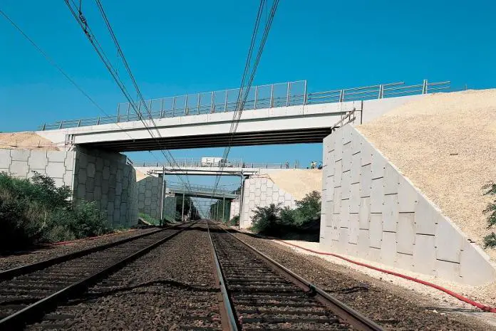
The main purpose of wing walls on an abutment is to contain backfill material behind the abutment wall and minimize carriageway settlement. High lateral earth pressures could result from the containment and compaction of backfill materials. Wingwalls can be found in abutments of bridges and and end of culverts.
The main purpose of wing walls on an abutment is to contain backfill material behind the abutment wall and minimize carriageway settlement. High lateral earth pressures could result from the backfill material being compacted and the soil being contained.
In essence, the retaining walls next to the abutment are wing walls. The walls may be separate from or a part of the abutment wall. The wing walls, which can be splayed at various angles or at a right angle to the abutment, hold the soil and fill that supports the roadway and approach embankment. The wing walls are often built at the same time as the abutments and from the same materials.
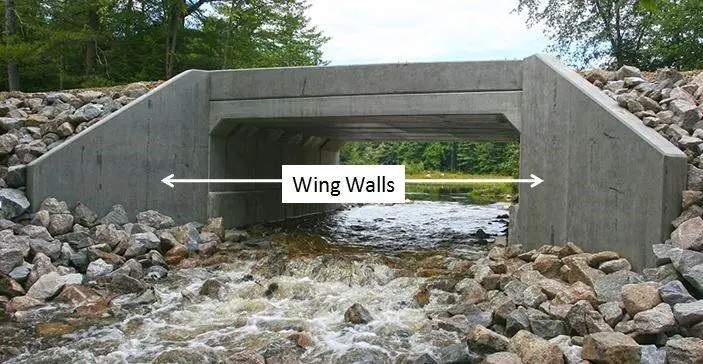
Types of Wing Walls
Wing walls can be categorised based on where they are located in relation to banks and abutments in the plan. The classification is as follows:
Free Standing Wing Walls
The foundation for free-standing wing walls is independent from the main abutment and is designed as a nominal cantilever retaining wall. In tis case, it is very possible for the abutment and wing walls to settle and tilt independently (differential settlement). Therefore, it is important to carefully plan the construction joints between the two structures in order to both allow for and conceal the relative movements. The wing walls can be positioned parallel to the abutment wall to accommodate the local topography, which makes compacting the backfill easy and eliminates any design issues, regardless of the deck’s skew angle.
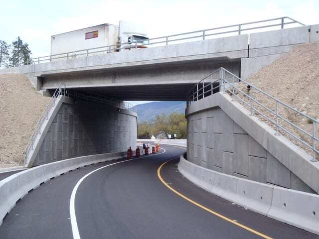
As an alternative, the wing walls can be constructed to follow the path of the over-road and support both the backfill and the parapet fencing. With this structural configuration, it will be more challenging to place the backfill material, and higher earth pressures will result from the restriction against sideways movement. As a result, building this type of design would be more expensive. Instead, wing walls that are tapered in height and spread out at 45 degrees to the abutment may be used.
Cantilevered Wing Walls
Use of horizontally cantilevered wings is a second method for creating wing walls parallel to the over-road. For lengths up to 12 m from the abutment, this type of construction is workable, although care must be used while planning the intersection of the wing and abutment wall. Although the building’s common base ensures that it settles as a single unit, it may be challenging to compact the backfill around the wings. This type of rigid construction supports high earth pressures, therefore at the very least, “at-rest” earth pressures should be taken into account when carrying out the design.
A three-dimensional structure is created using this style of abutment and wing wall arrangement. Although the typical metre-strip assumption is frequently utilised, it may not be the best foundation for a design. The existence of the wing walls greatly modifies the vertical and horizontal bending movements in the abutment, and if the wings are utilised to their full potential, an overall reduction in the steel needs is conceivable.
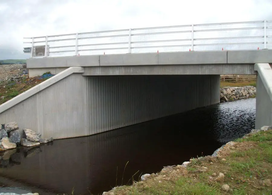
Since the wing walls’ self-weight significantly affects the stability and bending moments of the abutment wall, it is important to take this into account. Horizontal stresses on the wing walls are transmitted across the abutment wall and into the abutment corners. To carry the high torsional moments produced by the wing wall loading, the corner splays between the abutments and wing walls can be designed as vertical torsion blocks.
Design Considerations of Wing Walls
The following loads must be taken into account in the design of wing walls;
- Earth pressures from the backfill material
- Surcharge from live loading or compacting plant
- Hydrostatic loads from saturated soil conditions
The structural elements of the wall are typically designed to resist “at rest” earth pressures (K0), whereas the stability of the wall is typically designed to resist “active” earth pressures (Ka). The idea is that initial “at rest” pressures develop, and structural elements should be made to withstand these loads without failing. However, as the wall moves—either by rotating or sliding—the loads will be reduced to “active” pressure. Therefore, if the wall is built to withstand “active” earth pressures, it will stabilise if it shifts under “at rest” pressures.

