Statically determinate frames are usually two-dimensional planar structures whose unknown external reactions or internal member forces can be determined using only the three equations of equilibrium. Statically determinate frames are the basic functional frames of structural engineering, forming the backbone of countless structures from bridges to buildings. Understanding their analysis is fundamental to ensuring the stability and efficiency of most civil engineering structures.
The three equations of equilibrium sufficient for the analysis of statically determinate structures are;
∑Fx = 0; ∑Fy = 0; ∑Mi = 0
An indeterminate structure is one whose unknown forces cannot be determined by the conditions of static equilibrium alone. Additional considerations, such as compatibility conditions, are necessary for a complete analysis.
Nature of Statically Determinate Frames
As stated earlier, statically determinate frames are usually 2-dimensional structures. Three-dimensional frames are usually statically indeterminate and are more suited to computer-based finite element analysis.
The vertical members in statically determinate frames are referred to as the columns, while the horizontal members are referred to as the beams. Typically, the analysis of statically determinate frames involves the determination of the support reactions, internal stresses (bending moment, shear force, and axial force), and deflections.
Support Reactions
For simplified manual analysis, the support conditions considered in the analysis of frames are;
- Fixed support (consisting of three reactions)
- Pinned/hinged support (consisting of two reactions)
- Roller support (consisting of one reaction)
It therefore follows that when the number of support reactions in a frame exceeds three, special conditions such as internal hinges will be required to make the frame statically determinate. Such frames with internal hinges are usually referred to as compound frames. The degree of static determinacy or indeterminacy can then be calculated as follows;
ID = R – e – s
Where;
ID is the degree of static indeterminacy
e is the number of equilibrium equations (typically 3)
s is the number of special conditions in the structure
Alternatively,
If (3m + R = 3j + s), the structure is statically determinate.
Here:
m represents the number of members.
R represents the number of support reactions.
J represents the number of joints.
s represents the equations of condition (e.g., two equations for an internal roller and one equation for each internal pin).
Rearranging the equation above;
RD = (3m + R) – 3j – S
Where;
m = number of members.
r = number of support reactions.
j = number of nodes
S = number of special conditions
If the degree of static indeterminacy is less than 0, the frame is unstable. A structure is stable if it maintains its geometrical shape when subjected to external forces. Stability is important for ensuring the safety and functionality of a structure.
To obtain the support reactions in a statically determinate frame, it is usually sufficient to take the summation of moments about any of the supports or any point with a known condition (such as an internal hinge) and equate it to zero.
Loads and Actions on Frames
The skeletal framework of structural frames, composed of beams, columns, and trusses, bears the brunt of diverse forces and actions. Understanding and accurately analyzing these loads is paramount for ensuring the safety and functionality of the entire structure.
The types of loading found on frames are;
Point Loads: These concentrated forces act at discrete locations on a member. Columns sitting on a beam or the actions of secondary beams on primary beams are usually idealised as point loads. Their magnitude and position significantly influence the stress distribution within the frame.

Uniformly Distributed Loads (UDLs): Imagine a blanket of snow uniformly accumulating on a roof. This scenario represents a UDL, where the load acts with constant intensity across the entire length of a member. Self-weight of members is also idealised as uniformly distributed loads. Analyzing such loads involves calculating their total force based on the area they cover and their intensity.

Varied Distributed Loads: Not all distributed loads are uniform. Consider the wind pressure acting on a tall building, increasing in intensity towards the top due to aerodynamic effects. These loads can be modelled as linear (triangular loads) or non-linear (trapezoidal loads) functions of the member’s length, necessitating more complex analysis techniques like integration or employing equivalent uniform load representations.

Concentrated Moments: Imagine a child swinging on a monkey bar; the force applied at the bar’s end creates a concentrated moment, twisting the bar. This can also come from torsion being transmitted from another structural member or machinery. These moments directly influence the bending stresses within the member.

Beyond the fundamental loading idealisation, the world of structural loading extends beyond these fundamental categories:
- Line Loads: Picture the weight of a cable hanging on a support. These act along a linear element, requiring specialized analysis techniques.
- Hydrostatic and Earth Pressures: Retaining walls holding back water or soil experience continuous pressure from these fluids or packed earth, necessitating specialized analysis based on their specific intensity profiles.
- Impact Loads: A sudden blow, like a hammer strike, can create dynamic forces requiring specialized analysis to evaluate potential damage and ensure structural integrity.
Analysis of Statically Determinate Frames
The analysis of statically determinate frames involves several key steps. Let’s break it down:
- Identify the Frame: Begin by understanding the given frame’s geometry, member lengths, and support conditions. Clearly identify the structure and its supports (hinges, rollers, etc.). Determine the type and location of all applied loads (point loads, distributed loads, moments). Specify the material properties of the frame members (e.g., Young’s modulus, cross-sectional area). Confirm that the frame is statically determinate.
- Reaction Forces: Determine the reaction forces at each support using global equilibrium equations (vertical, horizontal, and moment equilibrium). Check for the force and moment equilibrium of the structure.
- Cut the Frame: Split the frame into separate members. Consider each member individually. Isolate each member by cutting it at a point of interest. Draw a free-body diagram of the isolated member. Apply the three equations of equilibrium to solve for the internal shear force, bending moment, and axial force (if applicable) at the point of interest. Repeat for other points of interest in each member.
- Internal Forces: Calculate the bending moment, shear, and axial force at selected locations of interest (typically member ends, midpoints, and points of maximum moment). These values help us understand the internal forces within the frame.
- Check for Deflections (Optional): Use beam deflection formulas or methods like the virtual work method to calculate deflections at specific points in the members. Compare the deflections to allowable limits specified in building codes or design criteria.
Solved Example
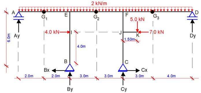
For the frame that is loaded as shown in the Figure below, find the support reactions and draw the internal stresses diagram. Internal hinges are located at points G1, G2, and G3 and beam JK cantilevers out at a height of 4m from column CF

Solution
RD = (3m + r) – 3n – S
m = 10 (ten members)
r = 6 (six reactions)
n = 11(eleven nodes)
S = 3 (three internal hinges)
RD = 3(10) + 6 – 3(11) – 3 = 0
This shows that the structure is statically determinate and stable.
Support reactions
Let ∑MG1L = 0; anticlockwise negative
(Ay × 2) – ((2 × 22)/2) = 0
Ay = 2.0 kN
Let ∑MG3R = 0; clockwise negative
(Dy × 4) – ((2 × 42)/2) = 0
Dy = 4.0 kN
Let ∑MG2L = 0; anticlockwise negative
(Ay × 7) – ((2 × 72)/2) + (By × 3) – (Bx × 6) – (4 × 2) = 0
But Ay = 2.0 kN
Hence, 7By – 6Bx = 43 ———— (a)
Let ∑MC = 0; anticlockwise negative
(Ay × 10) – ((2 × 10²)/2) + ((2 × 72)/2) + (4 × 4) + (By × 6) – (Dy × 7) + (5 × 1.5) – (4 × 7) = 0
But Ay = 2.0 kN, Dy = 4.0 kN
We then substitute the values into the above equation;
Hence By = 10.583 kN
Substituting the value of By into equation (a)
We obtain Bx = -1.1875 kN
Let ∑MB = 0; clockwise negative
(Cy × 6) + ((2 × 42)/2) – ((2 × 132)/2) – (4 × 4) + (Dy × 13) + (7 × 4) – (5 × 7.5) – (Ay × 4) = 0
But Ay = 2.0 kN, Dy = 4.0 kN.
We then substitute the values into the above equation;
Hence Cy = 22.417 kN
Let ∑MG2L = 0;
(Dy × 10) + (Cy × 3) – (Cx × 6) – ((2 × 10²)/2) – (5 × 4.5) – (7 × 2) = 0
But Dy = 4.0 kN, Cy = 22.42 kN
Therefore, Cx = -4.875 kN

Internal Stresses
Section A – EL (0 ≤ x ≤4.0)
Moment
Mx = Ay∙x – ((2x2)/2) = 2x – x2
At x = 0, MA = 0 (simple hinged support)
At x = 2.0m, MG1 = 2(2) – (2)2 = 0
∂Mx/∂x = Qx = 2 – 2x
When ∂Mx/∂x = 0, M = Maximum at that point
Hence, 2 – 2x = 0
x = 2/2 = 1.0m
Mmax = 2(1) – (1)2 = 1.0 kNm
At x = 4m
MEL = 2(4) – (4)2 = -8 kNm
Shear
∂Mx/∂x = Qx = 2 – 2x
At x = 0
QA = 2 kN
At x = 4m
QEL = 2 – 2(4) = -6 kN
Axial
No axial force in the section
Section B – IB (0 ≤ y ≤ 4.0)
Moment
My = Ax.y = 1.875y
At y = 0, MB = 0 (simple hinged support)
At y = 4m, MIB = 1.875(4) = 7.5 kNm
Shear
∂My/∂y = Qy = 1.875
QB – QIB = 1.875 kN
Axial
Ny + 10.483 kN = 0
NB – N1B = -10.483 kN
Section IUP – EB (4 ≤ y ≤ 6.0)
Mx = Ax.y – 4(y – 4) = 1.875y – 4y + 16
Mx = -2.125y + 16
At x = 4m, MIUP = -2.125(4) + 16 = 7.5 kNm
At x = 6m, MEB = -2.125(6) + 16 = 3.25 kNm
Shear
∂My/∂y = Qy = -2.125
QIUP – QEB = -2.125 kN
Axial
Ny + 10.483 kN = 0
NB – N1B = -10.483 kN
Section ER – G1L (4 ≤ x ≤7.0)
Mx = Ay.x – ((2x2)/2) + By (x – 4) + (1.875 × 6) – (4 × 2)
Mx = 2x – x2 + 10.483(x – 4) + 3.25
Mx = -x2 + 12.483x – 38.682
At x = 4m, MER = -(4)2 + 12.483(4) – 38.682 = -4.75 kNm
At x = 7m, MG1L = -(7)2 + 12.483(7) – 38.682 = 0
∂Mx/∂x = Qx = – 2x + 12.483
When ∂Mx/∂x = 0, M = Maximum at that point
Hence, – 2x + 12.483 = 0
x = 12.483/2 = 6.2415m
Mmax = -(6.2415)2 + 12.483(6.2415) – 38.682 = 0.274 kNm
Shear
∂Mx/∂x = Qx = – 2x + 12.483
At x = 4m, QER = -2(4) + 12.483 = 4.483 kN
At x = 7m, QG1L = -2(7) + 12.483 = -1.517 kN
Axial
Nx – 1.875 + 4 = 0
Nx = -2.125 kN
NER – NG1L = -2.125 kN
Coming from the right-hand side
Section D – FR (0 ≤ x ≤ 7.0)
Moment (clockwise negative)
Mx = Dy.x – ((2x2)/2) = 4x – x2
At x = 0, MA = 0 (simple hinged support)
At x = 4.0m, MG3 = 4(4) – (4)2 = 0
∂Mx/∂x = Qx = 4 – 2x
When ∂Mx/∂x = 0, M = Maximum at that point
Hence, 4 – 2x = 0
x = 4/2 = 2.0m
Mmax = 4(2) – (2)2 = 4.0 kNm
At x = 7m, MEL = 4(7) – (7)2 = -21 kNm
Shear
Since the sign convention changes when we are coming from the right, we reverse the signs.
∂Mx/∂x = Qx = 4 – 2x = -4 + 2x
At x = 0, QD = -4 kN
At x = 7m, QFR = -4 + 2(7) = 10 kN
Axial
No axial force on the section
Section C – JB(0 ≤ y ≤ 4.0)
Moment
My = Cx.y = 4.875y
At y = 0, MC = 0 (simple hinged support)
At y = 4m, MJB = 4.875(4) = 19.5 kNm
Shear
∂My/∂y = Qy= 4.875 = -4.875
QC – QJB = -4.875 kN
Axial
Ny + 22.417 kN = 0
NC – NJB = -22.417 kN
Section K – JR (0 ≤ x ≤1.50)
Moment
Mx = -5x
At x = 0, MK = -5(0) = 0
At x = 1.5m, MJR = -5(1.5) = -7.5 kNm
Shear
∂Mx/∂x = Qx = – 5 = 5
QK – QJR = 5 kN
Axial
Nx = -7 kN (Compression)
Section JUP – FB (4 ≤ y ≤ 6.0)
Moment
My = Cx.y – (5 × 1.5) – 7(y – 4)
My = -2.125y + 20.5
At y = 4m, MJUP = -2.125(4) + 20.5 = 12 kNm
At y = 6m, MFB = -2.125(6) + 20.5 = 7.75 kNm
Shear
∂My/∂y = Qy = -2.125 = 2.125
QJUP – QFB = 2.125 kN
Axial
Nx + 22.417 – 5 = 0
Nx = – 17.417 kN
NJUP – NFB = -17.417 kN
Section FL – G2R (7 ≤ x ≤ 10)
Mx = Dy.x – ((2x2)/2) + Cy (x – 7) + (4.875 × 6) – (7 × 2) – 5(x – 5.5)
Mx = 4x – x2 + 22.417(x – 7) – 5(x – 5.5) + 15.25
Mx = -x2 + 21.417 x – 114.169
At x = 7m, MFL = -(7)2 + 21.417(7) – 114.169 = -13.25 kNm
At x = 10m, MG2R = -(10)2 + 21.417(10) – 114.169 = 0
∂Mx/∂x = Qx = – 2x + 21.417
When ∂Mx/∂x = 0, M = Maximum at that point
Hence, – 2x + 21.417 = 0
x = 21.417/2 = 10.7085m
Hence no point of contraflexure exists in the section.
Shear
∂Mx/∂x = Qx = – 2x + 21.417 = 2x – 21.417
At x = 7m, QFL = 2(7) – 21.417 = -7.417 kN
At x = 10m, QG2R = 2(10) – 21.417 = -1.417 kN
Axial
Nx – 4.875 + 7 = 0
Nx = -2.125 kN
NER – NG1L = -2.125 kN
Bending moment diagram

Shear force diagram

Axial force diagram

To download the full calculation sheet, click HERE


very interesting solution