Structures deform when subjected to various conditions such as external loads, changes in temperature, differential settlement, or fabrication errors. Structural deformation is often considered in terms of rotation (slope) or translation (deflection).
The slope is the angle (in radians) that the elastic curve makes with the original neutral axis of the member, while deflection is the movement the structural member makes from the original neutral axis. In the design of structures, it is necessary to control the deflection for aesthetics and appropriate functionality (like cracking of finishes).
Statically determinate frames will deflect under the action of externally applied load, but will not be sensitive to indirect actions such as temperature difference and differential settlement. The deflection of statically determinate frames can easily be obtained using the virtual work method. For practical analysis of normal frames, the deflection due to shear can be ignored.
In beams and frames, bending moment is the major cause of deflection, while in trusses, axial forces are the major cause of deflection. Deformation due to shear is often very small and is neglected in most simple analyses. In the solved example that is downloadable in this post, the frame shown above is completely analysed, and the horizontal deflection at point B is obtained using the virtual work method. The analysis was carried out assuming linear elastic material response. Both the integration method (Mohr’s integral) and graphical method (Vereschagin’s diagram combination method) were used in the analysis.
Bending moment, shear force, and axial force contribute to the total deformation of a frame and the formula is given by;
δi = 1/EI∫Mm ds + k/GA∫Qq ds + 1/EA∫Nn ds ——- (a)
Where;
1/EI∫Mm d= Deflection due to bending moment
k/GA∫Qq ds = Deflection due to shear force
1/EA∫Nn d = Deflection due to axial force
Of all these, the highest contributor to deflection of statically determinate frames is the bending moment. Oftentimes, deformation due to shear force and axial forces are neglected, while in some analyses, they can be quite significant. The analysis below gives an example of the computation of deformation in a frame neglecting the shear and axial forces.
Hence displacement using Mohr’s integral is given by;
δi = 1/EI∫Mm ds ————– (b)
Where;
M = Moment due to externally applied load
m = Moment due to unit load applied at the point where the displacement is sought
EI = Flexural rigidity
The steps involved in the analysis of deflection of statically determinate frames can be summarised as follows:
- Analyse the frame completely and draw the final bending moment diagram due to externally applied load.
- Remove the externally applied load, and replace it with a virtual unit load, in the direction and location that the deflection is sought. For slopes, you place a unit moment at the point you wish to obtain the rotation.
- Analyse the frame completely under the action of the virtual load and draw the virtual bending moment diagram.
- Combine the bending moment equations or diagrams of the external and virtual loads and compute the value of the deflection.
Worked Example
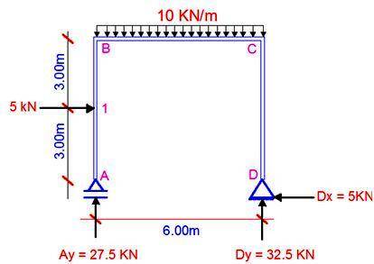
For the frame that is loaded as shown below;
(i) Find the support reactions
(ii) Draw the internal stresses diagram
(iii) Obtain the horizontal displacement at point B using both graphical and integration methods. (EI = Constant);
Solution
The degree of static indeterminacy is given by;
RD = (3m + r) – 3n – S
m = 3 (three members)
r = 3 (three reactions)
n = 4 (four nodes)
S = 0 (no internal hinge)
RD = 3(3) + 3 – 3(4) = 0
This shows that the structure is statically determinate and stable.
(i) Support Reactions
Let ΣMD = 0; clockwise negative
(Ay × 6) + (5 × 3) – (10 × 62/2) = 0
Ay = 27.5 kN
Let ΣMA = 0; clockwise negative
(Dy × 6) − (5 × 3) – (10 × 62/2) = 0
Dy = 32.5 kN
Let ΣFX = 0;
-Dx + 5 = 0, therefore,
Bx = 5 kN
(ii) Internal Stresses
Section 1-1 (A-1B) (0 ≤ y ≤ 3)
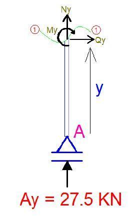
Bending Moment
My = 0 —- (1)
Shear
Qy = 0
Axial
Ny + 27.5 = 0
Ny = −27.5 kN
NA – N1B = −27.5 kN
Section 2-2 (1UP – BB) (3.0 ≤ y ≤ 6.0)

Bending Moment
My = −5(y−3)
∴ My = −5y + 15 —- (2)
At y = 3m,
M1UP = −5(3) + 15 = 0
At y = 6m
MBB = -5(6) + 15 = −15 kNm
Shear
Qy + 5 = 0
Qy = −5 kN
Q1UP – QBB = −5 kN
Axial
Ny + 27.5 = 0
Ny = −27.5 kN
NA – N1B = −27.5 kN
Section 3-3 (BR – CL) (0 ≤ x ≤ 6.0)

Mx = (27.5x) – (10 × x2/2) − (5 × 3)
Mx = −5x2 + 27.5x – 15 —– (3)
At x = 0,
MBR = −15 kNm
At x = 6m
MCL = −5(62) + 27.5(6) – 15 = −30 kNm
∂Mx/∂x = Qx = −10? + 27.5
At ∂Mx/∂x = 0, bending moment is maximum
Hence, −10x + 27.5 = 0
x = 27.5/10 = 2.75m
Hence the maximum sagging moment occurs at 2.75m
Mmax = −5(2.752) + 27.5(2.75) – 15 = 22.8125 kNm
Shear
Qx = – 10x + 27.5
At x = 0
QBR = 27.5 kN
At x = 6m
QCL = 27.5 – 10(6) = −32.5 kN
Axial
Nx + 5 = 0
Nx = −5 kN
NBR – NCL = −5 kN
Section 4-4 (D – CB) (0 ≤ y ≤ 6)

Bending Moment
My = −5y —– (4)
At y = 0,
MD = 0
At y = 6m
MCB = −5(6) = −30 kNm
Shear
Qy − 5 = 0
Qy = 5 kN
QD – QCB = +5 kN
Axial
Ny + 32.5 = 0
Ny = −32.5 kN
ND – NCB = −32.5 kN
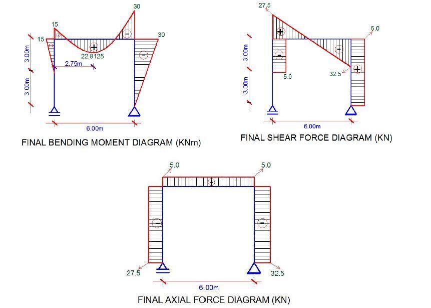
The internal stresses diagram of the frame is shown the figure below. The sign conventions are so important because of how they influence the results we obtain for the deflections. The internal stresses equations labelled (1), (2), (3), and (4) will be used for the integration method.
(iii) Horizontal displacement at point B
We will now remove the externally applied load, and place a unit horizontal load at point B of the structure. We will analyse the structure as usual and obtain the bending moment equations, and plot the bending moment diagram. In this case, we will neglect the axial and shear forces.
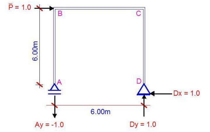
Support Reactions
Let ΣMD = 0; clockwise negative
(Ay × 6) + (1 × 6) = 0
Ay = −1.0
Let ΣMA = 0; clockwise negative
(Dy × 6) − (1 × 6) = 0
Dy = 1.0
Let ΣFX = 0;
−Dx + 1 = 0, therefore, Bx = 1.0
Internal Stresses due to Virtual unit Load (Bending moment only)
Section A-B (0 ≤ y ≤ 6)
My = 0 (no bending moment on the section) —- (1 & 2)
Section B-C (0 ≤ x ≤ 6)
Mx = −x ————- (c)
At x = 0, MBR = 0
At x = 6m, MCL = −6
Section D-C (0 ≤ y ≤ 6)
My = −y —————- (d)
At y = 0, MD = 0
At y = 6m, MCB = −6
The bending moment diagram due to the virtual unit load at point B is shown below;
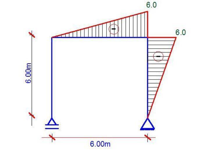
Deflection Using Mohr’s Integral
Therefore using the integration method, we can obtain the deflection at point B integrate section by section. Note that section A – B will be zero all through because in the bending moment diagram due to the unit load, there is no bending moment at the section and hence, everything there goes to zero;
δi = 1/EI ∫Mm ds
Therefore, horizontal displacement at point B is obtained by combining sections B – C and C – D

Deflection Using Vereschagin’s Rule (Graphical Method)
To achieve this we have to combine the diagrams for sections B-C and C-D for the external load and for the virtual load as shown below.
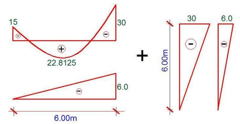
Realise that the shape in the original moment diagram for section B-C can be split as shown below;

Some diagram combination equations are shown below;
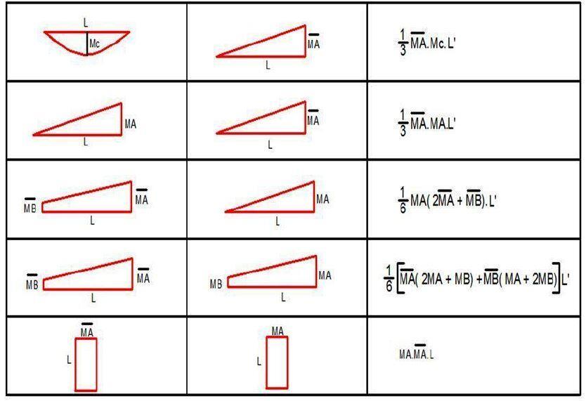
Hence;

δB = (1/6 × 15 × 6 × 6) − (1/3 × 45 × 6 × 6) + (1/3 × 30 × 6 × 6) + (1/3 × 30 × 6 × 6)
δB = 270/EI metres
Download the final solved example in PDF here and feel free to ask questions.



keep it up great engineer!
This comment has been removed by the author.