The deflection of statically indeterminate frames can occur under the action of externally applied loads, temperature difference, or differential settlement of support. These deformations are often expressed in the form of deflections (translations) and rotations (slope). The knowledge about the deformation of structures is very important in that we normally verify the serviceability limit state of structures through them. By being able to limit the deflections in a building, we can make the appearance pleasant, and protect the supported partitions and finishes from cracking.
The definition of slope and deflection is represented in the picture below, showing a simply supported beam deflecting under the action of a concentrated load P.
One of the methods of computing the deflection of statically indeterminate frames is the force method (virtual work method). In this approach, the frame is analysed using the force method, and the bending moment diagram due to the externally applied load obtained. Furthermore, a unit virtual load is placed on the basic system of the structure at the point where the deflection is sought, and analysed to also obtain the bending moment diagram. Using Verecschagin’s rule, it is possible to combine the bending moment diagram from the externally applied load with the moment diagram due to the virtual load to obtain the deflection at that point.
To learn how to apply force method to the analysis of indeterminate frames, click HERE
To learn about Vereshchagin’s rule, click HERE
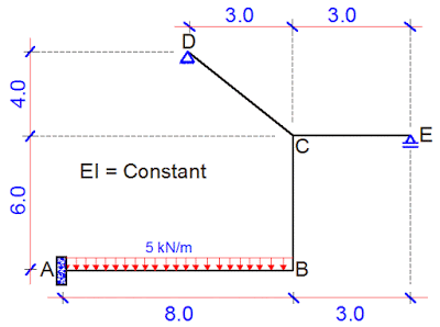
In this post, we are going to calculate the vertical deflection at point B of the frame loaded as shown below. A little consideration will show that the frame is indeterminate to the 3rd order. See previous posts on how to verify the determinacy of structures. Take EI = Constant
(1) Step 1
Reduce the structure to a basic system. A basic system is a system that is statically determinate and stable. The adopted basic system is as shown below;
(2) Step 2
Replace the support reactions with unit loads and analyse each load case independently. Furthermore, plot the bending moment due to the individual virtual loads. These diagrams can be plotted without finding support reactions. The different load cases and their corresponding bending moment diagrams are shown below;
CASE 1
CASE 2
CASE 3
(3) Step 3
Place the external load on the basic system, and plot the bending moment diagram.
(4) Step 4
Combine the various bending moment diagrams using the Verecschagin’s rule, and obtain the influence coefficients.
δ11 = Deflection at point 1 due to unit load at point 1
δ11 = 1/3(3 × 3 × 5) + (3 × 3 × 6) + 1/3(5 × 5 × 5) + 1/3(3 × 3 × 3) = 119.667/EI
δ12 = δ21 Deflection at point 1 due to unit load at point 2
δ12 = 1/3(3 × 4 × 5) + 1/2 [4 × (4 +10) × 6] – 1/2(5 × 5 × 10) – 1/2(3 × 3 × 10) = 66/EI
δ13 = δ31 Deflection at point 1 due to unit load at point 3
δ13 = -(3 × 3 × 6) + 1/6 [5 × (22 + 6) × 5] – 1/6 [3 × (6 + 6) × 3] = 44.667/EI
δ22 = Deflection at point 2 due to unit load at point 2
δ22 = 1/3(4 × 4× 5) + 1/6 [4(8 + 10) + 10(20 + 4) ] × 6 – (8 × 8× 10) = 1138.667/EI
δ23 = δ32 Deflection at point 2 due to unit load at point 3
δ23 = – 1/2 [3 × (4 +10) × 6] – 1/2 [10 × (11 + 3) × 8] = -686/EI
δ33 = Deflection at point 3 due to unit load at point 3
δ33 = 1/3(3 × 3× 3) + (3 × 3× 6) + 1/6 [11(22 + 3) + 3(6 + 11) ] × 8 = -497.667/EI
δ10 = Deflection at point 1 due to externally applied load
δ10 = 1/3(160 × 8) × 3 = -1280/EI
δ20 = Deflection at point 2 due to externally applied load
δ20 = 1/3(160 × 8 × 10 ) = -128/EI
δ30 = Deflection at point 3 due to externally applied load
δ30 = 1/12 [160 × (33 + 3) × 8] = – 384/EI
(5) Step 5
Insert the influence coefficients into the appropriate canonical equation and solve for X1, X2, and X3 which are the support reactions at the points where they are required.
119.667X1 + 66X2 + 44.667X3 = 1280
66X1 + 1138.667X2 – 686X3 = – 4266.667
44.667X1 – 686X2 + 497.667X3 = 3840
On solving;
X1 = 8.196 kN;
X2 = -0.09887 kN;
X3 = 6.844 kN
(6) Step 6
Obtain the final bending moment values and plot the diagram
Final Moments
Mi = M0 + M1X1 + M2X2 + M3X3
MA = -160 + (8.196 × 5) – (-0.09887 × 10) + (6.844 × 11) = -42.7473 kNm
MB = (8.196 ×- 3) – (-0.09887 × 10) + (6.844 × 3) = -3.0673 kNm
MCB = (8.196 ×- 3) – (-0.09887 × 4) + (6.844 × 3) = -3.660 kNm
MCL = (8.196 × 3) + (-0.09887 × 4) =24.19252 kNm
MCR = (6.844 × 3) = 20.532 kNm
The final bending moment diagram is shown below.
(7) Step 7
Place a unit vertical load at point B of the basic system and plot the bending moment diagram
(8) Step 8
Combine the resulting bending moment diagram with the final moment diagram form the externally applied load to obtain the deflection at point B. However, you should know that the complex bending moment on our final bending moment diagram can actually be split as shown below;
The subsequent combination to obtain the vertical deflection at point B is as shown below;
Therefore, the vertical deflection at point B;
δB = 1/3(42.747 × 8 × 8) – 1/3(40 × 8 × 8) + 1/6(3.067 × 8 × 8) = 91.318/EI metres
Thank you for visiting, and God bless you.
Like us on www.facebook.com/structville


