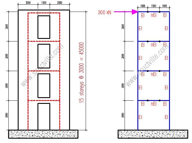
Shear walls are structural elements usually employed in tall buildings to assist in resisting lateral loads. Shear walls can be solid or pierced (coupled), depending on their location in the building. In the design of tall buildings, structural engineers normally throw the entire lateral load (say wind action) to the shear walls, which means that the columns will not be relied on for lateral stability. In a more practical scenario however, the shear walls and columns interact in resisting lateral loads, which can be taken into account.
[the_ad id=”498″]
In this post, we are going to review how shear walls can be modelled on Staad Pro software and consider the various accuracy levels with each method.
Let us consider the shear wall shown below;
Thickness of the wall = 250 mm
The wall is subjected to a lateral load of 300 kN at the top.
Model 1: Equivalent frame model
In this model, we represent the shear wall as an equivalent frame with representative stiffness for the various elements.
On modelling this Staad Pro, we obtained the result shown below;
The maximum horizontal deflection was obtained to be 158.376 mm.
Model 2: Plate modelling (Finite Element Mesh)
In this model, the shear wall is modelled as a full plate with approximate mesh size of (4 x 4) per square metre. The deflection due to the lateral load is given below;
The maximum horizontal deflection was obtained to be 156.588 mm.
It is important also to compare the deflection obtained by considering different mesh sizes in order to compare the accuracy of utilizing the equivalent frame model. Thank you for visiting Structville today, and God bless.


Nice Content Thanks for sharing .. BIM Consulting
BIM Solutions
BIM Implementation
Point Cloud to BIM conversion
Fabrication Drawings preparation
MEP F modelling
Please what is the parameter n in the Equivalent frame model at beam stiffness : nEI
n is a factor that can be used to represent the stiffness of the coupling beams in terms of the stiffness of the wall (for manual analysis). Definition of the section properties during computer modelling eliminates the need for that.
Pretty! This has been an incredibly wonderful article.
Thank you for providing these details.
Thanks for the article, but I have a doubt about the rigidity of the joint between the columns & the beams?
I think that if you have a stiffer beam the results will be farther, as the main concern in the frame model is how to properly model the joint between vertical and horizontal members.
Thanks again for this content.
Previous of contents f your book will help those who want to purchase them.