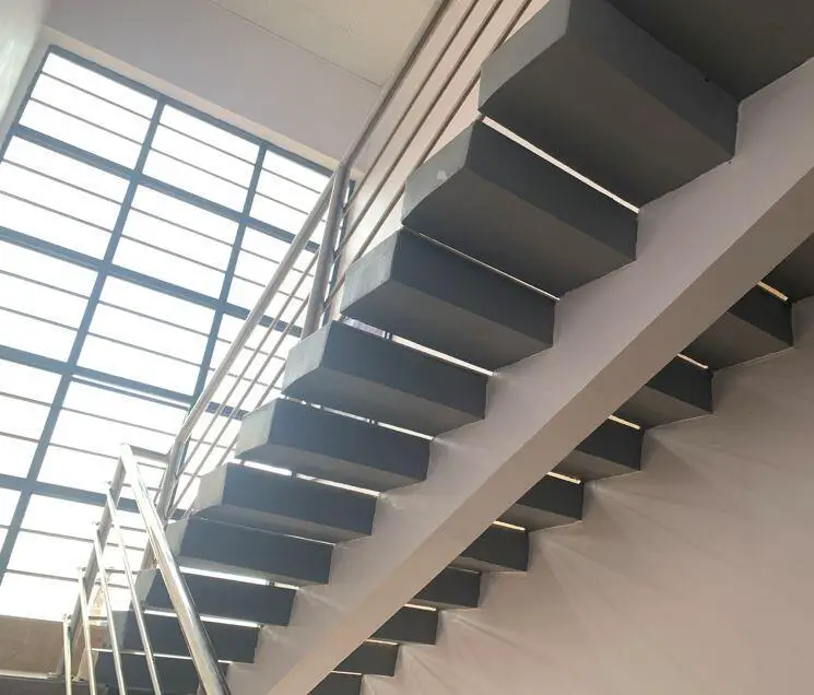
Cantilever stairs are a unique type of staircase where one end of the tread is rigidly supported by a beam or reinforced concrete wall, and the other end free. By implication, one end of the tread of the cantilever staircase appears to be floating in the air without support.
The design and construction of a cantilever staircase are expected to maintain and/or enhance the aesthetic appeal, while at the same time, ensuring that the staircase satisfies ultimate and serviceability limit state requirements.
The design of cantilever stairs, therefore, involves the selection of the adequate size of the supporting beams/walls, treads, and other accessories to support the anticipated load on the staircase and to also ensure the good performance of the staircase while in service. For reinforced concrete spine beams, the dimensions and reinforcements provided must satisfy all design requirements, while for steel spine beams, the section selected must satisfy all the requirements.
Moreover, the thickness of the tread must be adequate such that it does not undergo excessive vibration, cracking, deflection, or failure. The tread can be made of reinforced/precast concrete, timber, steel, glass, or composite sections.
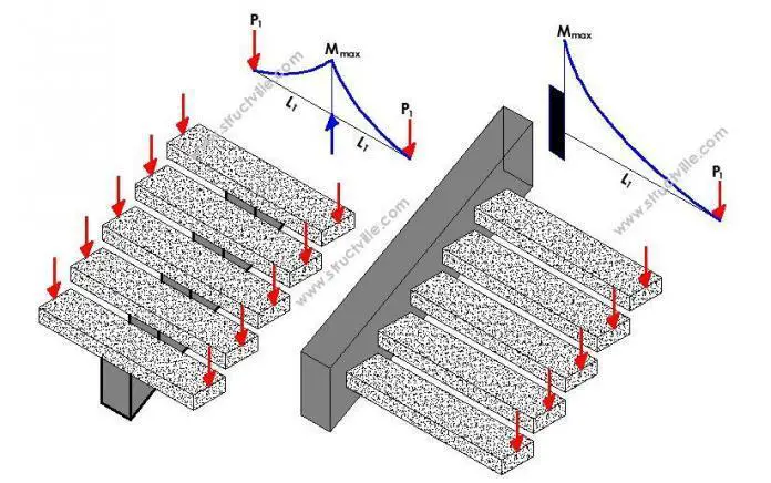
Structurally, there are two variations of cantilever staircases;
(a) Cantilever staircase supported by a central spine beam
(b) Cantilever staircase supported by a side spandrel beam or RC Wall
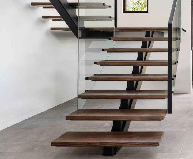
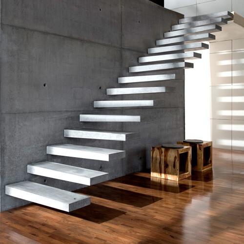
In the first case, the spine beam of the staircase is placed at the centre of the tread, with the two ends of the tread hanging free. In the second case, only one end of the tread is fixed to an adjacent wall where the spandrel beam is hidden to support the treads, and the other end is free. Alternatively, if the wall is a reinforced concrete wall, spandrel beams will no longer be required. Therefore, the latter has a longer moment arm than the former.

For the design of cantilever staircases, the use of uniformly distributed live loads should not be employed. Rather, the concentrated loads provided in Table 6.2 of EN 1991-1-1:2002 should be used. According to clause 6.3.1.2(5)P, the concentrated load shall be considered to act at any point on the floor, balcony or stairs over an area with a shape which is appropriate to the use and form of the floor. The shape may be assumed to be a square of 50 mm.
Furthermore, the possibility of upward loading on the cantilever staircase should also be considered.
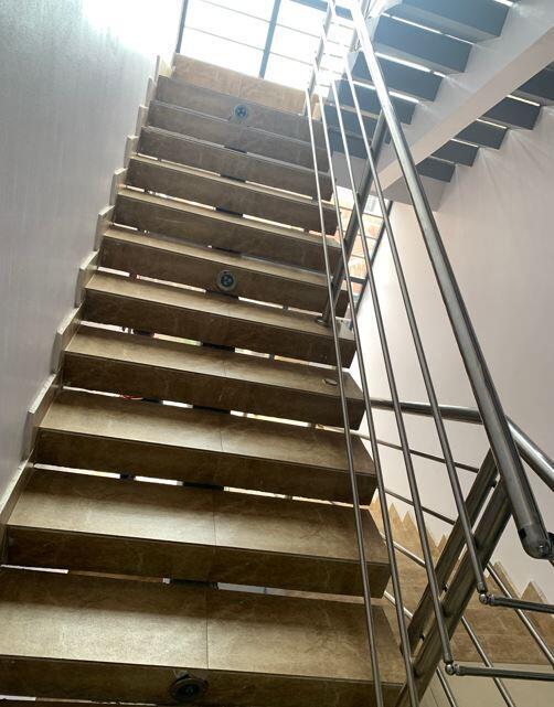
Worked Example on the Design of Cantilever Stairs
Design the treads and spine beam of the cantilever staircase in a proposed residential dwelling with the following information;
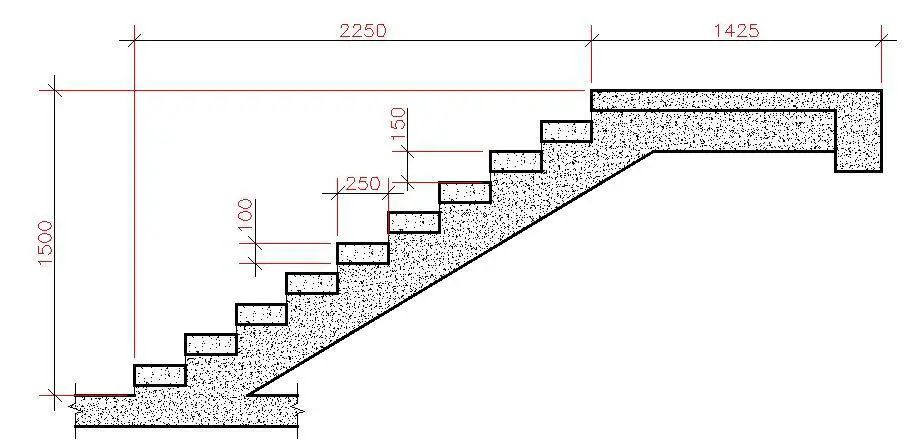
Width of staircase = 1200 mm
Going (width of riser) = 250 mm
Riser = 150 mm
Thickness of riser = 100 mm
fck = 25 N/mm2
fyk = 500 N/mm2
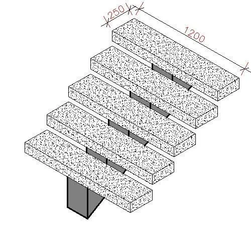
Load Analysis
For a staircase in a residential dwelling the uniformly distributed live load varies from 2.0 to 4.0 kN/m2, while the concentrated load (which can be used for local verification) varies from 2.0 to 4.0 kN. The exact value can be decided by the National Annex of the country.
Permanent Actions
Self weight of thread (UDL) = 25 × 0.1 × 0.25 = 0.625 kN/m
Finishes (allow 1.2 kN/m2) = 1.2 × 0.25 = 0.3 kN/m
Total UDL gk = 0.925 kN/m
Railings (allow) Gk = 0.5 kN (Concentrated load)
Variable Actions
Allow a variable concentrated load Qk of 3 kN (at the free end)
Ultimate Limit State
Permanent load (gk) = 1.35 × 0.925 = 1.25 kN/m
Permanent load (Gk) = 1.35 × 0.5 = 0.675 kN
Variable load (Qk) = 1.5 × 3 = 4.5 kN
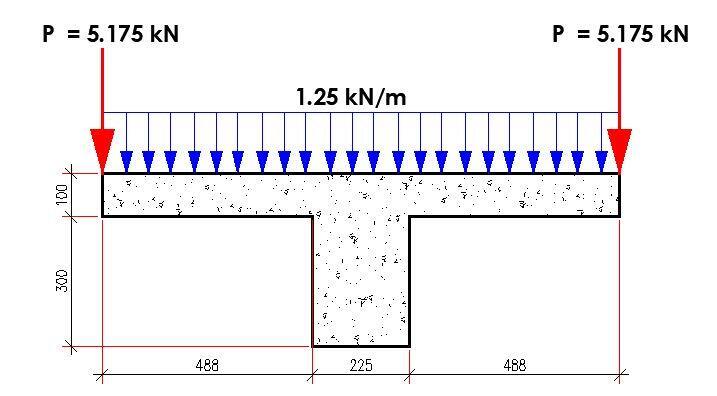
Maximum design moment (about the centreline of spine beam) = (1.25 × 0.62)/2 + (5.175 × 0.6) = 3.33 kNm
Maximum shear (about the centreline of spine beam) = (1.25 × 0.6) + (5.175) = 5.925 kN
Flexural Design
Design bending moment; M = 3.3 kNm
Effective depth of tension reinforcement; d = 68 mm
Redistribution ratio; d = min(Mneg_red_z3 / Mneg_z3, 1) = 1.000
K = M / (b × d2 × fck) = 0.115
K’ = 0.207
K’ > K – No compression reinforcement is required
Lever arm; z = min(0.5 × d × [1 + (1 – 2 × K / (h × acc / γC))0.5], 0.95 × d) = 60 mm
Depth of neutral axis; x = 2 × (d – z) / λ = 20 mm
Area of tension reinforcement required; As,req = M / (fyd × z) = 127 mm2
Tension reinforcement provided; 3H12 As,prov = 339 mm2
Minimum area of reinforcement – exp.9.1N; As,min = max(0.26 × fctm / fyk, 0.0013) × b × d = 23 mm2
Maximum area of reinforcement – cl.9.2.1.1(3); As,max = 0.04 × b × h = 1000 mm2
PASS – Area of reinforcement provided is greater than area of reinforcement required
Crack control
Maximum crack width; wk = 0.3 mm
Design value modulus of elasticity reinf – 3.2.7(4); Es = 200000 N/mm2
Mean value of concrete tensile strength; fct,eff = fctm = 2.6 N/mm2
Stress distribution coefficient; kc = 0.4
Non-uniform self-equilibrating stress coefficient; k = min(max(1 + (300 mm – min(h, b)) × 0.35 / 500 mm, 0.65), 1) = 1.00
Actual tension bar spacing; sbar = 93 mm
Maximum stress permitted – Table 7.3N; ss = 326 N/mm2
Steel to concrete modulus of elast. ratio; acr = Es / Ecm = 6.35
Distance of the Elastic NA from bottom of beam; y = (b × h2 / 2 + As,prov × (acr – 1) × (h – d)) / (b × h + As,prov × (acr – 1)) = 49 mm
Area of concrete in the tensile zone; Act = b × y = 12195 mm2
Minimum area of reinforcement required – exp.7.1; Asc,min = kc × k × fct,eff × Act / ss = 38 mm2
PASS – Area of tension reinforcement provided exceeds minimum required for crack control
Quasi-permanent moment; MQP = 1.0 kNm
Permanent load ratio; RPL = MQP / M = 0.30
Service stress in reinforcement; ssr = fyd × As,req / As,prov × RPL = 49 N/mm2
Maximum bar spacing – Tables 7.3N; sbar,max = 300 mm
PASS – Maximum bar spacing exceeds actual bar spacing for crack control
Deflection control
Reference reinforcement ratio; ρm0 = (fck)0.5 / 1000 = 0.00500
Required tension reinforcement ratio; ρm = As,req / (b × d) = 0.00748
Required compression reinforcement ratio; ρ’m = As2,req / (b × d) = 0.00000
Structural system factor – Table 7.4N; Kb = 0.4
Basic allowable span to depth ratio ; span_to_depthbasic = Kb × [11 + 1.5 × (fck)0.5 × ρm0 / (ρm – ρ’m) + (fck)0.5 × (ρ’m / ρm0)0.5 / 12] = 6.404
Reinforcement factor – exp.7.17; Ks = min(As,prov / As,req × 500/ fyk, 1.5) = 1.500
Flange width factor; F1 = 1.000
Long span supporting brittle partition factor; F2 = 1.000
Allowable span to depth ratio; span_to_depthallow = min(span_to_depthbasic × Ks × F1 × F2, 40 × Kb) = 9.606
Actual span to depth ratio; span_to_depthactual = Lm1_s1 / d = 8.824
Shear Design
Using the maximum shear force for all the spans
Support A; VEd (say) = 6 kN
VRd,c = [CRd,c.k. (100ρ1 fck)1/3 + k1.σcp]bw.d ≥ (Vmin + k1.σcp)bw.d
CRd,c = 0.18/γc = 0.18/1.5 = 0.12
k = 1 + √(200/d) = 1 + √(200/68) = 2.714 < 2.0, therefore, k = 2.00
Vmin = 0.035k3/2fck1/2
Vmin = 0.035 × 2.003/2 × 251/2 = 0.494 N/mm2
ρ1 = As/bd = 339/(250 × 68) = 0.0199 < 0.02;
σcp = NEd/Ac < 0.2fcd
(Where NEd is the axial force at the section, Ac = cross sectional area of the concrete), fcd = design compressive strength of the concrete.) Take NEd = 0
VRd,c = [0.12 × 2 × (100 × 0.0199 × 25 )1/3] × 250 × 68 = 15005.755 N = 15 kN
Since VRd,c (15 kN) < VEd (6 kN), No shear reinforcement is required.
However, nominal shear reinforcement can be provided as H8 @ 150 c/c.
Summary of the tread (going) design
Thickness = 100 mm
Reinforcement = 3H12 (Top and Bottom)
Links = H8 @ 150 c/c.
Design of the Spine Beam
To design the spine beam, it is very important to transfer the load from the treads to the top of the spine beam. In other words, the spine beam will be subjected to its self-weight and the load from the treads. It will be very important to also consider the effects of asymmetric loading (when the live load is acting only on side of the staircase). This can lead to the development of torsional stresses on the beam.
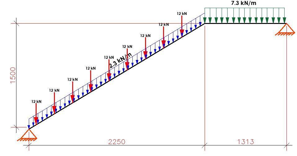
Ultimate limit state load transferred from treads to beam = 6 kN + 6 kN = 12 kN (concentrated loads)
Load transferred from the landing area (say) = 5 kN/m
Width of spine beam = 225 mm
Depth = 300 mm
Self weight of spine beam (drop) = 1.35 × 25 × 0.225 × 0.3 = 2.278 kN/m
Self weight of the stepped area = 1.35 × 0.5 × 0.15 × 0.225 = 0.02278 kN/m
Total uniformly distributed load on the flight = 2.3 kN/m
Total uniformly distributed load on the landing = 2.278 + 5 = 7.278 kN/m
The spine beam was loaded as shown below;
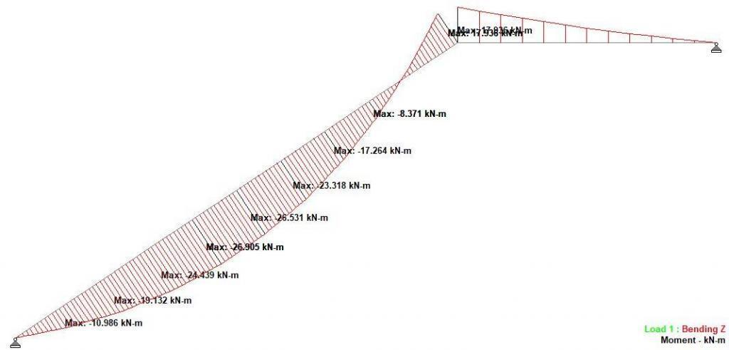
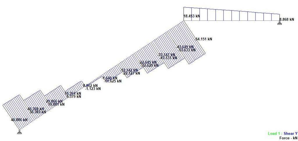
The analysis results are shown below;
Flexural Design
Design bending moment; M = 26.9 kNm
Effective depth of tension reinforcement; d = 264 mm
K = M / (b × d2 × fck) = 0.086
K’ = 0.207
K’ > K – No compression reinforcement is required
Lever arm; z = min(0.5 × d × [1 + (1 – 2 × K / (h × acc / γC))0.5], 0.95 × d) = 242 mm
Depth of neutral axis; x = 2 × (d – z) / λ = 54 mm
Area of tension reinforcement required; As,req = M / (fyd × z) = 255 mm2
Tension reinforcement provided; 2H16 As,prov = 402 mm2
Minimum area of reinforcement – exp.9.1N; As,min = max(0.26 × fctm / fyk, 0.0013) × b × d = 77 mm2
Maximum area of reinforcement – cl.9.2.1.1(3); As,max = 0.04 × b × h = 2700 mm2
PASS – Area of reinforcement provided is greater than area of reinforcement required
Shear Design
Angle of comp. shear strut for maximum shear; θmax = 45 deg
Strength reduction factor – cl.6.2.3(3); v1 = 0.6 × (1 – fck / 250) = 0.552
Compression chord coefficient – cl.6.2.3(3); αcw = 1.00
Minimum area of shear reinforcement – exp.9.5N; Asv,min = 0.08 N/mm2 × b × (fck)0.5 / fyk = 161 mm2/m
Design shear force at support ; VEd,max = VEd,max_s1 = 54 kN
Min lever arm in shear zone; z = 242 mm
Maximum design shear resistance – exp.6.9; VRd,max = αcw × b × z × v1 × fcwd / (cot(θmax) + tan(θmax)) = 201 kN
PASS – Design shear force at support is less than maximum design shear resistance
Design shear force ; VEd = 54 kN
Design shear stress; vEd = VEd / (b × z) = 0.994 N/mm2
Angle of concrete compression strut – cl.6.2.3; θ = min[max(0.5 × sin-1(min(2 × vEd / (acw × fcwd × v1),1)), 21.8 deg), 45deg] = 21.8 deg
Area of shear reinforcement required – exp.6.8; Asv,des = vEd × b / (fyd × cot(θ)) = 206 mm2/m
Area of shear reinforcement required; Asv,req = max(Asv,min, Asv,des) = 206 mm2/m
Shear reinforcement provided; 2H8 @ 175 c/c
Area of shear reinforcement provided; Asv,prov = 574 mm2/m
PASS – Area of shear reinforcement provided exceeds minimum required
Maximum longitudinal spacing – exp.9.6N; svl,max = 0.75 × d = 198 mm
EXTRA:
The structural analysis result revealed a high compressive axial load on the spline beam. As a result, it will be important to check the interaction of bending moment and axial force, as typically will be done in the design of reinforced concrete columns. This was checked and found satisfactory.
Furthermore, the possibility of a torsional moment on the spline beam when the live load is asymmetrically loaded should also be checked.




I need complete design of those stairs
This guide about cantilever stairs is really amazing. This is helpful.
Very Helpfull design for cantilever stair