8.7 C
New York
Thursday, June 12, 2025
Home Blog Page 48

Load Transfer from Slab to Beams – A Comparative Analysis

In the design of reinforced concrete structures, floor loads are usually transferred from slabs to beams, and from the beams, the loads are transferred to the columns. Ultimately, the columns transfer the superstructure load to the foundation supporting the structure. Load transfer from slab to beams is one of the most intriguing aspects of reinforced concrete design, especially for beginners.

Usually, slab pressure loads (force per unit area) are transferred to the supporting beams as line loads (force per unit length). The line load can be triangular, trapezoidal, or partially distributed on the beam. Depending on the analytical method employed in the design, some idealisations can be made in order to simulate load transfer from slab to beam. The most popular methods of transferring slab load to beams are;

  1. Finite element analysis
  2. Yield line method
  3. Approximate method using formula

Finite element analysis is suited more to computer calculation since it can be a very lengthy process when done by hand. In this method, the slab is divided into finite element meshes connected by nodes. The reactive forces on each node along the beam are transferred to the beams (which must be broken into finite elements too with nodes connected to the slab).

In the yield line method, the most appropriate yield lines are constructed (usually at 45° angles) on the slab, and the corresponding load on each part of the yield line transferred to the beam adjacent to it. For two-way slabs, this method usually leads to trapezoidal and triangular loads on the beams.

In the manual design of structures, some formulas can be used to idealise slab loads on beams as uniformly distributed loads. The main reason for this is to simplify manual analysis since it is not a very accurate method. The results obtained from the method are usually very conservative.

Some of the formulas can be obtained from Reynolds and Steedman (2005) for transfer of load from two-way slab to beams. The formulas are presented below;

Two-way slab (ly/lx < 2)
Long span: p = nlx/2(1 – 1/3k2)
Short span: p = nlx/3

One-way slab (ly/lx > 2)
Long span: p = nlx/2
Short span: p = nlx/5

Where;
n = load from slab
ly = length of long side of the slab
lx = length of short side pf the slab
k = aspect ratio = ly/lx

In this article, we are going to review load transfer from slab to beams using the three approaches;

(1) Full finite element analysis of beams and slabs using Staad Pro
(2) Yield line method of load transfer using Staad Pro
(3) Manual method using formula

CASE 1: Two way slab of dimensions (5m x 6m) simply supported by beams on all sides and subjected to a pressure load of 10 kN/m2
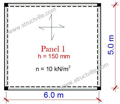
two way slab

(a) Finite element analysis

finite element analysis 1

Long span beam:
Maximum span moment = 73.063 kNm
Support moment = -2.71 kNm
End shear = 37.6 kN

Short span beam:
Maximum span moment = 54.495 kNm
Support moment =-0.814 kNm
End shear = 31.9 kN

(b) Yield line method
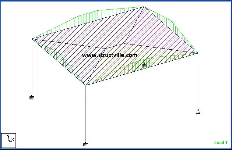
Floor load on slabs
Yield line method 2

Long span beam:
Maximum span moment = 76.562 kNm
Support moment = -9.897 kNm
End shear = 39.4 kN

Short span beam:
Maximum span moment = 46.987 kNm
Support moment =-5.096 kNm
End shear = 30.151 kN

(c) Manual analysis using formula
k = ly/lx = 6/5 = 1.2
Load on long span beam = nlx/2(1 – 1/3k2) = [(10 x 5)/2] x [1 – 1/(3 x 1.22)] = 19.212 kN/m
Maximum span moment = ql2/8 = (19.212 x 62)/8 = 86.454 kNm
End shear = ql/2 = (19.212 x 6)/2 = 57.636 kN

Load on the short span beam = nlx/3 = (10 x 5)/3 = 16.667 kN/m
Maximum span moment = ql2/8 = (16.667 x 52)/8 = 52.084 kNm
End shear = ql/2 = (16.667 x 5)/2 = 41.6675 kN

Summary Table for Two-Way Slab

Analytical MethodLy – Span Moment (kNm) Ly – Support Moment (kNm)Ly – End shear (kN)Lx – Span Moment (kNm)Lx – Support Moment (kNm)Lx – End shear (kN)
Finite Element Analysis73.0632.7137.654.4950.81431.9
Yield line method76.5629.89739.446.9875.09630.151
Formula86.4540.0057.63652.0840.0041.66

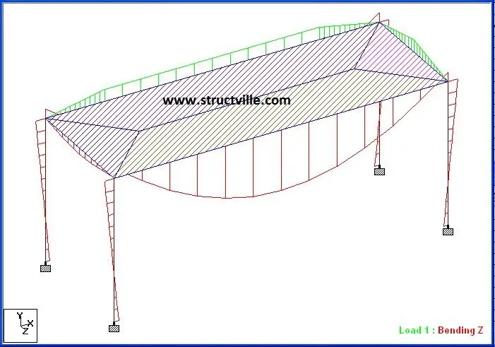
CASE 2: One-way slab of dimensions (2.5 m x 7 m) simply supported by beams on all sides and subjected to a pressure load of 10 kN/m2

k = ly/lx = 7/2.5 = 2.8
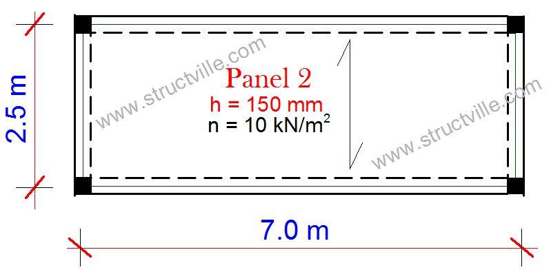
one way slab system

(a) Finite Element Analysis

one way slab finite element analysis 1

Long span beam:
Maximum span moment = 60.689 kNm
Support moment = -6.337 kNm
End shear = 29.7 kN

Short span beam:
Maximum span moment = 12.091 kNm
Support moment = +2.81 kNm
End shear = 11.6 kN

(b) Yield line method
one way slab floor load

Long span beam:
Maximum span moment = 63.4 kNm
Support moment = -9.9 kNm
End shear = 35.9 kN

Short span beam:
Maximum span moment = 6.16 kNm
Support moment = -0.346 kNm
End shear = 7.81 kN

(c) Manual analysis using formula
Load on long span beam = nlx/2 = (10 x 2.5)/2 = 12.5 kN/m
Maximum span moment = ql2/8 = (12.5 x 72)/8 = 76.56 kNm
End shear = ql/2 = (12.5 x 7)/2 = 43.75 kN

Load on the short span beam = nlx/5 = (10 x 2.5)/5 = 5 kN/m
Maximum span moment = ql2/8 = (5 x 2.52)/8 = 3.906 kNm
End shear = ql/2 = (5 x 2.5)/2 = 6.25 kN

Summary Table for One-Way Slab

Analytical MethodLy – Span Moment (kNm) Ly – Support Moment (kNm)Ly – End shear (kN)Lx – Span Moment (kNm)Lx – Support Moment (kNm)Lx – End shear (kN)
Finite Element Analysis60.6896.33729.712.0912.8111.6
Yield line method63.49.935.96.160.3467.81
Formula76.560.0043.753.9060.006.25

Discussion of results

(a) Two-way slab systems
(1) In the long span direction, finite element analysis and yield line method gave very close results for bending moment and shear forces. Manual analysis overestimated the load transferred.
(2) In the short span direction, the yield line method underestimated the load transferred to the short span beams when compared with finite element analysis. The formula method gave results that are close to finite element analysis.
(3) Manual analysis using formula gave bending moment values that can be used for design purposes but generally overestimated the shear forces. In the long span direction, the sagging moment can be redistributed to the supports by 10% (reduce the span moments by 10% and take the value taken away as support moment).

(b) One-way slab systems
(1) As with two-way slabs, finite element analysis and yield line method gave very close results for bending moment and shear forces in the long span beams. Manual analysis overestimated the load transferred.
(2) In the short span direction, the yield line method underestimated the load transferred to the short span beams when compared with finite element analysis. Manual analysis using formula underestimated the load transferred.
(3) As with two-way slabs, manual analysis using formula gave bending moment values that can be used for design purposes, but overestimated the shear forces in the long span beams. The shear force and bending moment in the short-span beam were underestimated when the formula method was used.
(4) In the long span direction, the sagging moment can be redistributed to the supports by 10% (reduce the span moments by 10% and take the value taken away as support moment) when using formula method.

Conclusion and Recommendation

(1) In a strict technical sense, there is nothing like a one-way action for a slab supported by beams on all the edges. There is always a two-way action even though it is greater in the long span.
(2) Formula should not be applied when assessing the shear force induced in beams supporting floor loads.
(3) Yield line method of load transfer from slab to beams should be used for manual design of structures, despite the more onerous computational effort.

Cost of building a duplex in Nigeria (foundation to DPC)

The cost of building a duplex in Nigeria varies, and it is generally influenced by the size of the building, the price of construction materials, the design specifications, the expertise and machinery required, and the environment/location. Depending on the soil condition of the area, a special foundation may be needed for the building, which will affect the overall cost of the project. For instance, a raft foundation will be more expensive than a pad foundation, while deep foundations such as piles will be more expensive than raft foundation.

The construction cost of a building can also be influenced by the nature of the contract, and it will be in the best interest of the client to hire a professional consultant or project manager who will represent his interest throughout the duration of the project.

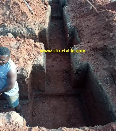
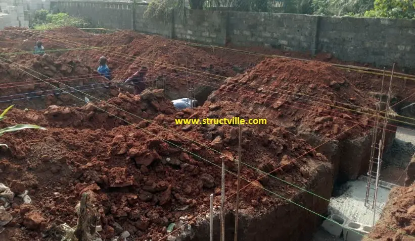
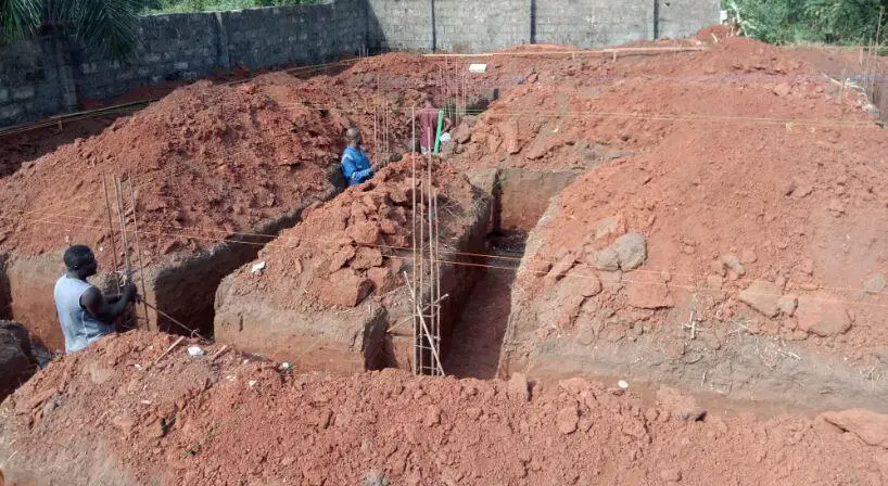
excavation of trench
Excavation of trench for construction of a duplex by Structville Integrated Services Limited

Intending homeowners must engage professionals during the design stage, in order to get their project right from the scratch. A complete construction drawing in Nigeria should include;

  • Full sets of architectural drawing
  • Structural drawings
  • Electrical drawings, and
  • Mechanical drawings

The client representative or project manager is expected to advise the client on how to get the drawings approved for construction depending on the jurisdiction. Requirements for approval varies from state to state and from local government to local government.

Construction of foundation
The construction of the substructure of a building (foundation) is very critical because any mistake in a foundation is very difficult and expensive to correct. A poorly constructed foundation can compromise the integrity of the entire building. Foundation construction has very little to do with the specifications of the architect, but he has to inspect the setting out of the building to ensure that his design has been followed. The major costs and activities involved in the foundation of a building such as residential duplexes are basically functions of engineering design.

substructure works
Setting out of column starter bars in a substructure

A good design will minimise cost, identify possible challenges in the construction of the building, guarantee the integrity and structural stability of the building, and subsequently lead to fewer difficulties during construction. Now that you are here, it is important that you play your part as an intending homeowner and engage registered professionals in your projects. This can help stop the problem of building collapse in Nigeria.

In this article, let us briefly review the cost of constructing a simple duplex from the foundation to the DPC (ground floor slab). The building is to be constructed in a semi-urban area in South-Eastern Nigeria. As stated earlier, the cost is dependent on the drawing provided by the structural engineer and not by guesswork. The actual price of materials in the locality, delivery to site, and labour will also influence the cost. Therefore, the cost provided in this article may not reflect the cost of materials in your locality.

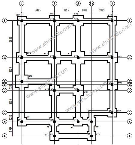
The plan of the building is shown below;

Foundation layout of a
Foundation layout of a duplex

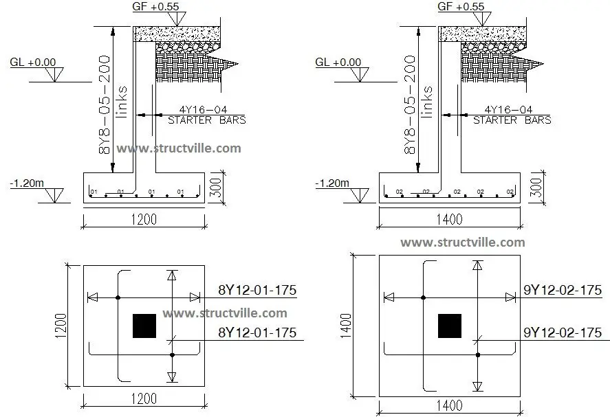
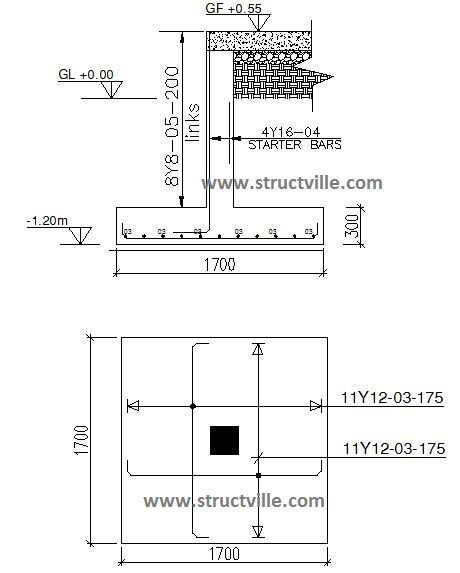
From the foundation layout, it can be seen that the structural engineer provided three types of pad foundations (BT1, BT2 and BT3). The size of any foundation is determined by the strength of the soil, and the load coming from the column. The details of the pad bases are given below;

Base Type 1 and 2
Base Type 1 and Base Type 2 structural details
Base Type 3
Base Type 3 structural details

The activities that will take place in the construction of the foundation are;

(1) Setting out works
(2) Excavation works
(3) Reinforcement works
(4) Formwork
(5) Concrete works
(6) Blockwork
(7) Backfilling and compaction
(8) Casting of ground floor slab

(1) Setting out
Width of building = 12.275 m
Length of building = 15.7 m

If we make a setback of 1.2 m from all sides of the building line for the profile board, the total perimeter of the profile board will be 65.55 m. At 1.5m spacing, we will need 45 pegs, and 20 pieces of 2″ x 3″ softwood. Let us assume that the equipment needed for setting out is available except lines.

(a) 2” x 3” soft wood – 25 pcs @ ₦400 = ₦12,500
(b) 2” x 2” pegs – (3 bundles @ 20 pieces per bundle) @ ₦1200 = ₦3,600
(c) Nails – 1 bag of 2 inches nail, and 1 bag of 3 inches nail = ₦26,000
(d) 6 rolls of lines = ₦2,000

Labour and supervision cost (say) = ₦30,000

Total cost of setting out = ₦74,100

(2) Excavation works
(a) Excavation of 19 column bases according to structural drawings to a depth not less than 1200 mm to receive blinding for pad foundation – Total volume = 42.42 m3
19 column bases @ ₦1000 = ₦19,000

(b) Excavation of strip footing 690 mm wide and 950 mm deep to receive mass concrete strip footing – Total volume = 70.13 m3
Labour cost for 30 partitions @ ₦2000 = ₦60,000
Supervision cost (say) = ₦20,000

Sub-total for excavation = ₦99,000

column starter bar setting out
Excavation and column setting out works

(3) Concrete works
(a) Provision of 50 mm thick weak concrete blinding (1:3:6) on column bases to receive footing reinforcement – Total volume = 1.8 m3
Cement – 8 bags @ ₦4,100 per bag = ₦32,800
Sand – 1.98 tonnes @ ₦3500 per tonne = ₦6,930
Granite – 2.52 tonnes @ ₦16000 per tonne = ₦40,320

(b) Provision of concrete with strength not less than 25 MPa after 28 days for the column bases – Total volume = 10.7 m3
Cement – 65 bags @ ₦4,100 per bag = ₦226,500
Sand – 12 tonnes @ ₦3500 per tonne = ₦42,000
Granite – 15 tonnes @ ₦16000 per tonne = ₦240,000

(c) Provision of concrete with strength not less than 20 MPa after 28 days for the mass concrete strip footing – Total volume = 8.5 m3
Cement – 51 bags @ ₦4,100 per bag = ₦209,100
Sand – 9.35 tonnes @ ₦3,500 per tonne = ₦32,725
Granite – 12 tonnes @ ₦16,000 per tonne = ₦192,000

(d) Casting of Column Stubs (1.5 m3)
Cement – 8 bags @ ₦4,100 per bag = ₦32,800
Sand – 1.65 tonnes @ ₦3500 per tonne = ₦5,775
Granite – 2.1 tonnes @ ₦16000 per tonne = ₦33,600

Labour cost for mixing, pouring and consolidation of concrete = ₦159,600
Supervision cost = ₦50,000

Cost of concrete works = ₦1,304,150

(4) Reinforcement Works
(a) Column base mat reinforcement
50 lengths of Y12 mm @ ₦3,700 per length = ₦185,000

(b) Column starter bars
20 lengths of Y16 mm @ ₦8,000 per length = ₦160,000

(c) Column links
13 lengths of Y8mm @ ₦2,100 per length = ₦27,300

(d) Binding wire
20 kg roll of binding wire @ ₦14,000 per roll = ₦14,000

Labour cost for cutting, bending, and placement of reinforcement = ₦40,000

Cost of reinforcement works = ₦426,300

(5) Blockwork
(a) Total number of 9 inches blocks required to raise the building to DPC = 1600 blocks
1600 pieces of 9” blocks @ ₦350 per block = ₦560,000

Labour cost for laying of blocks = ₦144,000
Cement for mortar = 32 bags @ ₦4100 per bag = ₦131,200
Sand = 10 tonnes @ ₦22,000 = ₦22,000
Supervision = ₦20,000

Cost of blockwork = ₦877,200

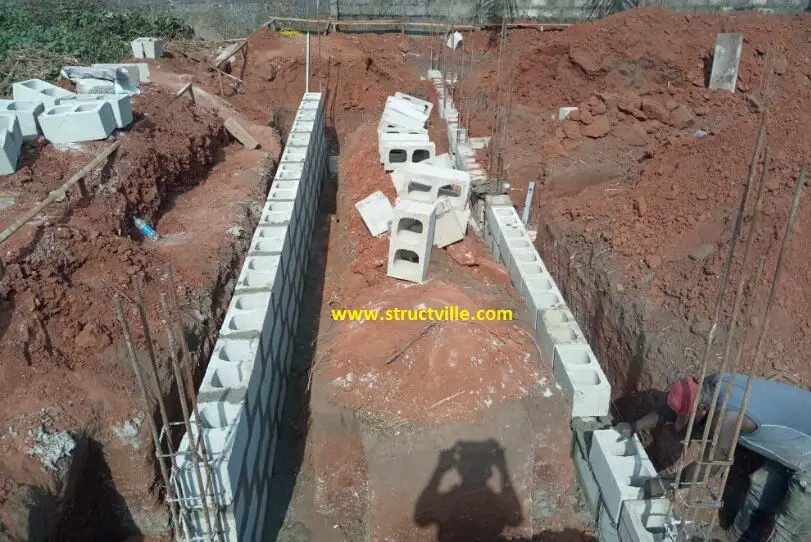
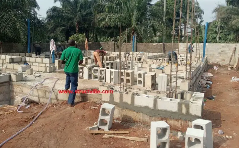
setting of blocks in foundation
Blockwork in substructure

(6) Formwork
(a) Provide formwork for sides of columns up to a height not less than 1225 mm.
20 pieces of 1” x 12” x 12 plank @ ₦1,350 per plank = ₦27,000

Labour cost for formwork preparation and placement = ₦15,000

Cost of formwork = ₦42,000

(7) Backfilling and compaction
(a) Backfill and compact substructure to a height not less than 550 mm above ground level with selected backfill material. Total volume = 100 m3
33 trips (165 tonnes) of laterite @ ₦12,000 per trip = ₦396,000
Labour cost for filling and compaction = ₦50,000

Total Cost of filling and compaction = ₦446,000

(8) Damp proof membrane
(a) Provide and install damp-proof membrane over an area not less than 181 m2
181 m2 of high density polythene sheet @ ₦385 per m2 = ₦69,685

Damp proof membrane = ₦69,685

(9) BRC mesh
(a) Provide and Install A142 BRC MESH (TOP) over an area not less than 181 m2
181 m2 of A142 BRC Mesh @ ₦1,200 per m2 = ₦217,200

Labour cost for installation = ₦5,000

Total Cost of BRC mesh = ₦222,200

(10) Ground floor Slab
(a) Cast ground floor slab over an area not less than 181 m2 and concrete of volume = 27.15 m3
Cement – 163 bags @ ₦4,100 per bag = ₦668,300
Sand – 30 tonnes @ ₦3500 per tonne = ₦105,000
Granite – 40 tonnes @ ₦16000 per tonne = ₦640,000

Labour cost for mixing, pouring and consolidation of concrete = ₦170,000
Supervision cost = ₦50,000
Casting of ground floor slab = ₦1,633,300

Therefore, the tentative cost of raising the building from foundation to DPC is ₦5,193,935 without the contractor’s profit and overhead.

Building off from DPC
Completed substructure of a duplex by the author

For design, construction, and professional management of your building project, contact;

Structville Integrated Services Limited
E-mail: info@structville.com
Phone call: +2348060307054
Whatsapp: +2347053638996

Standards for Highway Materials in Nigeria

Earth materials are extensively utilised for highway construction in Nigeria. It has been recognised that high quality lateritic soils which are abundant in Nigeria can be used as fill, sub-base, and base course materials in highway construction. In this article, we are going to show the recommended standards for highway materials based on Federal Ministry of Works Specifications for Roads and Bridges (1997).

Generally, the material to be used for highway construction shall not be excavated from swamps, marshes or bogs. Furthermore, they shall be free from peat, logs, stumps, roots, and other perishable or combustible materials. Top soils and highly organic clays and silt shall not to be used for constructiont. All clays having liquid limit exceeding 80% or plasticity index exceeding 55 should be rejected.

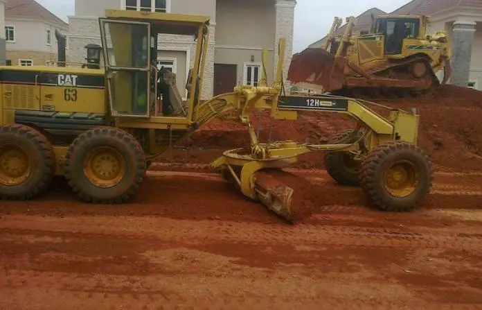
earthworks

The basic recommendations given for base course materials are for crushed stone base in clauses 6250, 6251, and 6252. Therefore, the recommendations for sub-base course materials shall be deemed to apply to base course earth materials too. Recommendations for crushed stone base will not be covered in this this article.

List of Tests for selection of highway earth materials
The lists of test that shall be conducted for highway materials are;

(1) Plasticity tests
(2) Grading tests
(3) Compaction tests
(4) Laboratory CBR tests

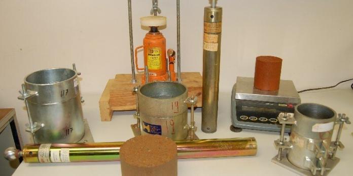
CBR testing machine 1

Materials for sub-base course (Type 1) – Heavy Traffic
(1) The percent by weight passing No 75μm sieve shall not be greater than 35%
(2) The material passing 425μm sieve shall have a liquid limit not more than 35% and plasticity index of nit more than 12%
(3) The material shall have unsoaked CBR value of 80% using Modified AASHTO or West African Standard Compaction and minimum CBR of 30% after 24 hours soaking.

Materials for sub-base course (Type 2) – Light Traffic
(1) The percent by weight passing No 75μm sieve shall not be greater than 35%
(2) The material passing 425μm sieve shall have a liquid limit not more than 35% and plasticity index of nit more than 12%
(3) The material shall have unsoaked CBR value of 80% using Modified AASHTO or West African Standard Compaction and minimum CBR of 20% after 24 hours soaking.

Materials for sub-base course (Type 3) – Substandard materials
When the site engineer recognises that suitable materials are not available for use, and the materials slightly fall short of the required standard, the following measures can be adopted;

(1) Compacting the material to a lesser density at the wet side of the optimum to contain the tendency of the material to shrink or swell.
(2) Mechanical stabilisation of the material with sand (if available) to reduce the fines content

Inclusion of women in construction industry

Growing up as a Nigerian from one of the least developed communities, I have identified that our continent Africa and Nigeria in particular has a problem in infrastructure that is yet to be addressed.

Engineering as a discipline is male dominated both globally and locally. For us to retain the women we have, we need to create more opportunities for them whether as colleagues, wives, sisters or friends.

Inclusion of women in construction

In the construction industry generally, it is perceived that only men work on site. Everyday at work, I hear a lot of people say things like, “this is my first time of seeing a female engineer on site”. What this literarily means is that we have left the work for men alone, allowing them to decide a significant part of our lives – building homes.

intersectionality 1

There is need for us to begin to rethink the way we build infrastructure and who builds them. This will begin from design to procurement, construction, finishes, and even commissioning. On the long run, this will help us to recognize talent inclusively, bridge the gender gap, increase the retention of women, and also work towards achieving global goals.

For example, on a construction site, you will discover that most safety wears, boots and signs are designed to be more compatible with men. Some read – ‘Men at Work’. Some are with visual signals that denotes men.

162 1628253 gender equality feminism gender symbol social equality women

As a starting point to inclusion on construction sites, access to construction areas including walk-ways, stairs, and temporary platforms should include women in the design. Also, initial site planning and management should include restrooms for women as well as men.

While some women are working hard and pushing to be outstanding in the profession whether as technical leaders, engineers and project managers, there are some reasons why many people feel women should not be on site.

Firstly engineering and construction is male oriented, as workers on site are already used to taking instructions from men, which has been a norm for centuries.

20190130192656 GettyImages 552721707 1

Secondly women are believed to have poor leadership skills and as such receive bais from both the society and those above them who ought to be an excellent support to enhance their productivity and performance.

Thirdly women are believed to be too sensitive amidst a few others which are not true. Perhaps on site when they delegate responsibilities and follow up to ensure that it gets done, managers may conclude that those are small things. One way to help is by constructively critising them when necessary, evaluating their performance for the sole purpose of providing useful feedback that could lead to self-improvement.

NAWIC image 4

Overall, we recognize that over 90% of workers in construction are men. There is need for managers, leaders, engineers and decision makers to begin to shape the future through inclusion, shared opportunities, equity and promoting a culture of respect and empathy.

Modelling and Analysis of Spherical LPG Tanks (Horton Sphere)

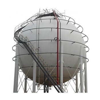
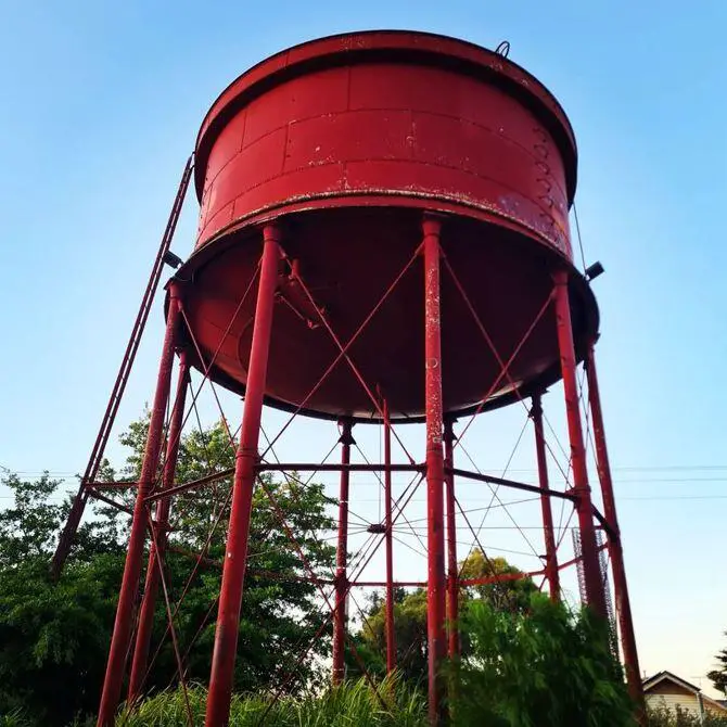
Spherical tanks (Horton Sphere) are used in several applications such as water storage, nuclear cooling, and storage of liquefied gases such as liquefied natural gas (LNG) and liquefied petroleum gas. One of the most common utilization of spherical vessels in the industry is pressurized gas storage because they can withstand higher internal pressure and have fewer size limitations than cylindrical pressure vessels. Horton Spheres usually contain pressurized gas inside the steel shell. The shell is supported by heavy steel columns which transmit the load to a reinforced concrete foundation.

LPG TANK
Fig 1: Typical LPG spherical tank

Spherical tanks have high rigidity and durability. According to Khan (2015), the performance of a 200 m3 liquefied petroleum gas (LPG) tank with a wall thickness of 24 mm under 1.7 MPa pressure was evaluated after it had been in operation for three years. The result showed high resistance to micro cracking and shell deformation, with minimal wall thinning.

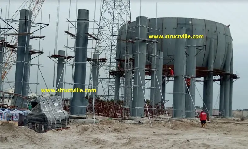
LPG TANK FARM UNDER CONSTRUCTION 1
Fig 2: LPG Tank farm under construction in Lagos, Nigeria
TANK FARM CONSTRUCTION
Fig 3: Author at an LPG tank farm construction site in Lagos

In this article, we are going to evaluate the potentials of Staad Pro software in the modeling and analysis of LPG sphere tanks. We are not going to deeply evaluate the design considerations for such structures but you should know that the tank shell should be able to withstand the vapour pressure from the liquefied petroleum gas.

This pressure is dependent on temperature and the design temperature is selected from the environment under consideration. For example, LPG gas cylinder pressure (LPG gas bottle pressure) is 0 kPa at -43ºC and goes up to 2482 kPa at 70ºC.

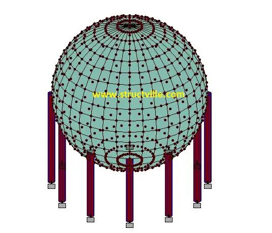
In this article, let us model and analyse an LPG sphere tank on Staad Pro with the following data;

(1) Diameter of tank = 20 m
(2) Thickness of tank shell = 25 mm
(3) Columns – Hollow circular steel columns of external diameter 900 mm (thickness = 40 mm)
(4) Design pressure = 1700 kPa

LPG TANK MODEL ON STAAD PRO
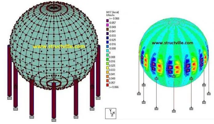
Fig 4: Spherical LPG model on Staad Pro
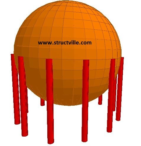
3D RENDERING OF LPG SPHERE TANK
Fig 5: 3D rendering of LPG tank model

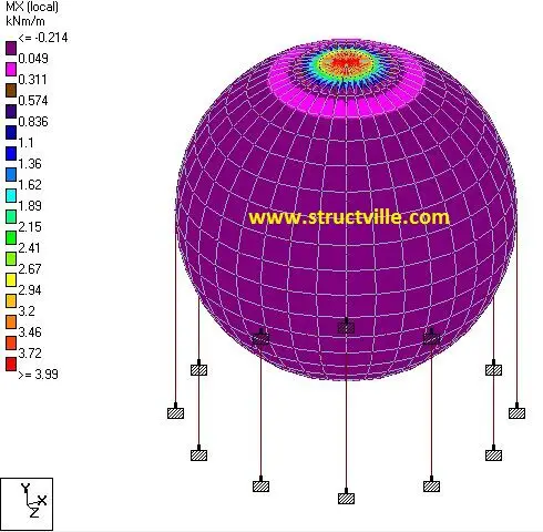
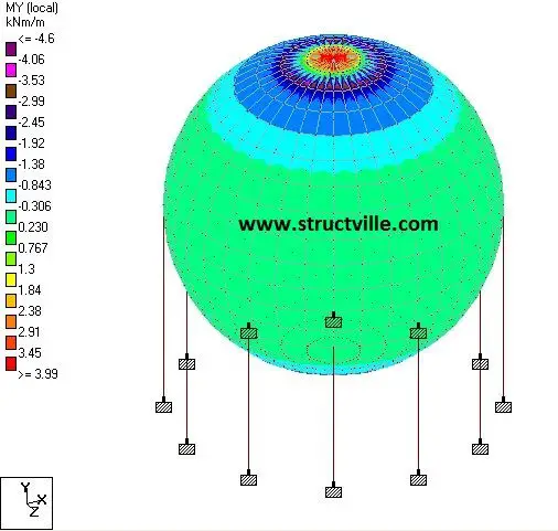
When analysed on Staad Pro for a gas pressure of 1700 kPa, the following results were obtained.

Bending moment on LPG Tank Shell
Fig 6: Lateral bending moment on the tank shell due to gas pressure
MY 1
Fig 7: Longitudinal bending moment on the tank shell due to gas pressure
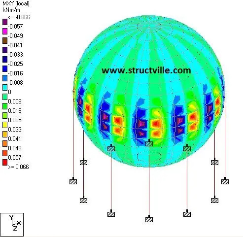
MXY
Fig 8: Twisting moment on the tank shell due to gas pressure
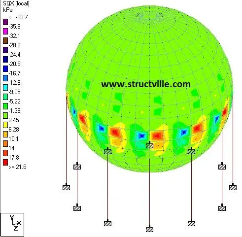
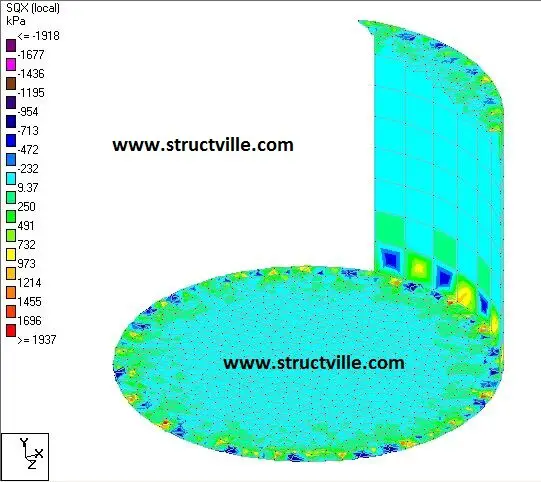
SQX
Fig 9: Lateral shear stress on the tank shell due to gas pressure
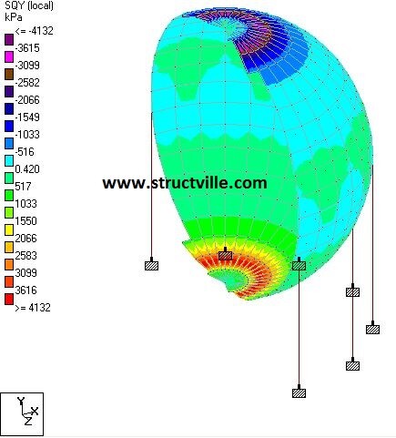
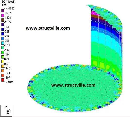
SQY
Fig 10: Longitudinal shear stress on the tank shell due to gas pressure
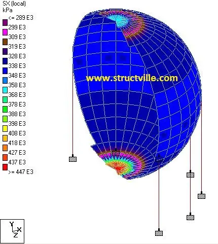
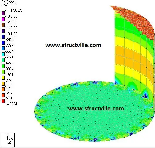
SX
Fig 11: Lateral axial tension on the tank shell due to gas pressure
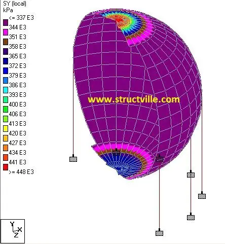
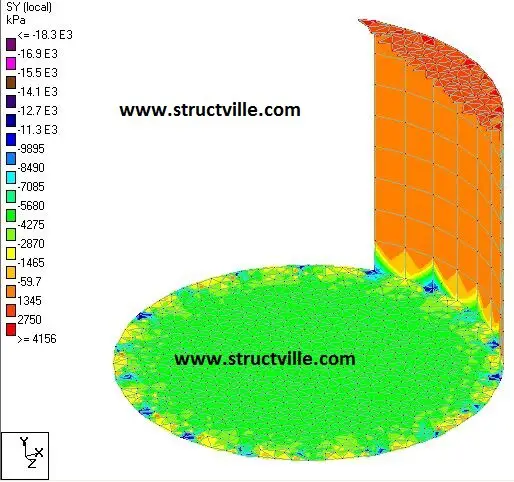
SY
Fig 12: Longitudinal axial tension on the tank shell due to gas pressure

The video tutorial for this modeling and analysis is available on special request by sending an e-mail to ubani@structville.com. Also free contact us for special designs related to infrastructures in oil and gas facilities and tank farms.

References
Khan F.A. (2015): Spherical tanks in energy storage systems. A PhD thesis subimtted to the Department of Mechanical Engineering, WORCESTER POLYTECHNIC INSTITUTE .

How to price/quote for concrete works

In civil engineering construction works, contractors bidding for a job are always required to specify the rate they will use in executing a given item of work. In a competitive bidding, the client will review the rates supplied by the bidders, and award the contract to the person he finds most suitable.

Concrete is a common construction material that is basically made from cement, sand, gravel, and water. The main aim of this article is to teach you how to build up your rate, and quote for concrete in construction works.

The unit of concrete in construction is specified in cubic metres (m3). For instance, if a floor slab has a net area of 250 m2, and a thickness of 150 mm, the volume of concrete required will be stated as (250 x 0.15 = 37.5 m3). In the bill, a contractor is expected to state the cost of casting a cubic metre of the specified grade concrete (say grade 25), which can be used to relate the cost of casting the entire slab.

Note that the rate supplied by the contractor is expected to include the cost of materials, plant, transportation, labour, and contractor’s profits.

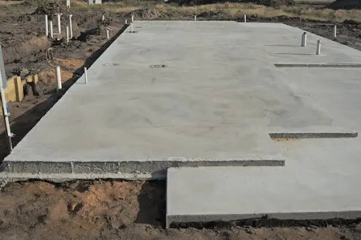
concrete slab

There are basic considerations to make while quoting for concrete because you should not bid too high or too low. It is possible for contractors to have a wide difference in their rates for the same job. For a competitive tender without bias, a company that is going to hire equipment will likely bid higher than a company that has its own equipment. The same goes with labour, transport facilities, etc.

Bidding for a job should be an intelligent process, and the contractor should know his capacity as it will likely influence his cost and profitability. The cost of casting concrete in one day is not the same with casting it for two days. Therefore, a contractor’s capacity can enable him bid higher or lower depending on the context.

Bidding war


To make it simpler, let us give an idea on how you can build up your rate for grade 25 concrete.

In the past, we have made a post on how you can achieve grade 25 concrete on site. We were able to show that the mix ratio of 1:2.5:3.5 can yield grade 25 concrete. Let us assume you wish to use this mix ratio in building your rate.

The total volume in the mix ratio is given by;
1 + 2.5 + 3.5 = 7

Cement
Ratio of cement by volume = 1/7
Density = mass/volume
Mass of cement required = (1/7) x 1440 = 205.7 kg
Making allowance for shrinkage = 1.54 x 205.7 = 316.77 kg
Number of bags of cement required per of concrete = 316.77/50 = 6.33 bags (use 7 bags)

Sand
Ratio of sand by volume = 2.5/7
Density = mass/volume
Mass of sand required = (2.5/7) x 1650 = 589.285 kg
Making allowance for shrinkage = 1.54 x 589.285 = 907.498 kg
Making allowance for waste = 1.2 x 907.498 = 1088.99 kg/m3

Granite
Ratio of granite by volume = 3.5/7
Density = mass/volume
Mass of granite required = (3.5/7) x 1650 = 825 kg
Making allowance for shrinkage = 1.54 x 825 = 1270.5 kg
Making allowance for waste = 1.15 x 1270.5 = 1461.075 kg/m3

Build up of rates

(a) Materials
Mix ratio = 1:2.5:3.5
Cement = 7 bags/m3
Sand = 1088.99 kg/m3
Aggregate = 1461.075 kg/m3

Market Prices of Materials including transportation to site;
Cement = ₦4100 per bag
Sharp sand = ₦ 3500 per tonne
Granite aggregate = ₦ 16000 per tonne (the current basic rate of granite is about NGN 9000 per tonne, but the cost of transportation is currently so high)

Cost of materials
Cost of cement per cubic metre concrete = 7 x 4,100 = ₦28,700
Cost of sharp sand per cubic metre of concrete = 3500 x 1.08899 = ₦3,812
Cost of granite per cubic metre of concrete = 16000 x 1.461 = ₦23,376
Total Material Cost = ₦55,888 per cubic metre of concrete

(b) Plant
Rate of Concrete mixer per cubic metre of concrete = ₦600
Rate of vibrator per cubic metre of concrete = ₦350
Operator = ₦500
Total Plant Cost = ₦1,450 per cubic metre of concrete

(c) Labour
Labour output (production and placement) per cubic metre of concrete = ₦7,000

Total cost of production = ₦55,888 + ₦1,450 + ₦7,000 = ₦64,388

(d) Profit and Overhead (20%)
1.2 x ₦64,388 = ₦77,205

Therefore the cost of producing one cubic metre of grade 25 concrete is ₦64,388

The West African Standard Compaction Test

The West African Standard (WAS) compaction test is a type of compaction procedure that utilises intermediate compaction energy (compactive effort) for densification of soils. It has been recommended for densification of soils for highway construction in Nigeria and some other West African Countries. The compaction energy of WAS lies between the compaction energy of BS Light (Standard Proctor) and BS Heavy (Modified Proctor).

The details of the West African Standard compaction test using BS Mould are as follows;

Volume of mould = 1000 cm3 = 0.001 m3
Number of blows = 10
Number of soil layers = 5
Weight of rammer = 4.5 kg
Height of fall = 0.4575 m

Therefore, the compaction energy (compactive effort) of WAS using BS Mould is given as follows;
Compactive effort = (9.81 x 10 x 5 x 4.5 x 0.4575)/0.001 = 1009816.875 N.m/m3 = 1009.816 kN.m/m3.

The details of the West African Standard compaction test using the CBR Mould are as follows;

Volume of mould = 2305 cm3 = 0.002305 m3
Number of blows = 25
Number of soil layers = 5
Weight of rammer = 4.5 kg
Height of fall = 0.4575 m

Compactive effort using CBR mould = (9.81 x 25 x 5 x 4.5 x 0.4575)/0.002305 = 1094.527 kN.m/m3.

It can be observed that WAS compaction test an intermediate compaction energy when compared with BS Light (605.49 kN.m/m3) and BS Heavy (2726.5 kN.m/m3).

Applications of WAS compaction in Nigeria
(1) Laboratory compaction of sub-base course according to Federal Ministry of Works Specification (1997)
(2) Soaked CBR test of base course (clause 6200)
(3) Soaked CBR test of sub-base course Type 2 (clause 6200)

Tips for Civil Engineering Job Interviews

Landing a good job soon after graduation is the dream of many young civil engineering students. On the other hand, as a professional engineer grows on the job, there might come a time when he will want to switch from one civil/structural engineering job to another. This can happen for a lot of reasons which may be personal or professional. The process of finding a new job often involves passing through interviews during which the employers will try to know as much as possible about the person interested in working for them.

The questions asked during interviews are usually related to the ideals of the organisation, and the requirements of the position they are seeking to fill. All civil engineering firms do not offer the same services. As a result, it is important to research properly on the company, know what they do, and what they stand for. Employers will also try to take a look at you, and at how your attitude and appearance will reflect their brand. Once again, it strongly depends on the area that the company will be needing your services.

Interview

Having said that, let us look at what you should expect during interviews for graduate trainee/internship roles in various civil engineering companies.

Consultancy firms
Consultancy firms are usually involved in civil engineering designs, drawings, supervision, and project management. For beginner roles, they will likely be more interested in your basic knowledge of civil engineering structures, analyses, design, and drawings. They will expect the candidate to be sound, smart, and trainable. Having a basic knowledge of AUTOCAD, and other civil engineering software will be added advantage.

Small and medium scale consultancy firms usually conduct in-house interviews, and will be more interested in your technical capacity and how well you will fit into their team. For such job assessments, you might be given simple beams and slabs to analyse and design, and asked questions on the behaviour of some construction materials such as concrete. A hands-on test on AUTOCAD and other civil engineering software might be done.

On the other hand, bigger/multinational firms who have distinguished Human Resources Department might wish to conduct a larger scale interview, or might outsource the recruitment process to external consultants. In this case, the interview questions will usually extend to leadership and competency-based questions. For such bigger firms, the interview panel might consist of only one engineer and other members who might have studied sociology or business administration.

In such cases, therefore, you should widen your scope and present yourself as a general problem solver, as it will excite them more. Your ability to analyse and design complex frame structures might not really excite them as much as when you tell them how you solved a complex social problem during a volunteering activity. Apart from your technical capacity, they are very much interested in your leadership, emotional, and social credentials. Smaller design firms may not pay much attention to those aspects.

0 800

You should note that in both cases, the organisation and the interviewers understand that you are a fresh graduate with no experience, hence, they are simply looking out for a few basic things during the interview. Your ability to communicate, answer questions smartly, coordinate yourself properly, and present yourself as a quick learner will earn you serious consideration.

If you have made any significant achievement such as publications, verifiable unique designs, significant contributions, or possession of a unique skill, you should try and talk about them so that they can take you seriously from the onset. It simply gives the impression that you are an achiever. What might distinguish you from another civil engineering graduate may be your ability to write computer programs or codes, and in this digital age, any serious organisation will likely give you preferential treatment.

In summary, find the right time to talk about your special skills and experience during interviews. An organisation might wish to hire you because you did your student internship with a company they rate highly, or perhaps because you have participated in the construction of a green building, which is an area they might be interested in.

Generally, from the way you present yourself and answer questions, they will decide whether to hire you or not. As hinted earlier, your technical ability and academic records will excite smaller firms than bigger firms. This is because when an interview is done in-house, you are going to be interviewed by engineers and other technical people who will eventually become your direct colleagues. But in bigger firms, the requirements often appear broader as they seem to focus more on ‘general problem solving’ skill than specialised technical ability. Therefore, it is important to understand your interviewers based on the kind of questions they ask, and know how to answer accordingly.

best interview

Note that consultants often go to site visitation, supervision, and meeting with clients or contractors. As a result, you will be representing your firm on many occasions as an image of the organisation. Therefore, your ability to dress properly and communicate effectively is of paramount importance. It will be observed during the interview, and if your communication skills are poor, it might limit your chances.

Construction firms
There are some companies that are mainly builders/contractors and rarely do designs. Interviews for civil engineering jobs with such companies are usually not focused on designs and theory of structures but on site practices. You might be asked questions like:

How do you set out a building?
How do you establish levels?
What concrete mix ratio will give you grade 25 concrete?
How can you calculate the quantity of tiles needed to tile an area?
Describe the process of constructing a flexible pavement?
What is the minimum gauge of aluminium roof required to roof a steel roof building?
How do you prepare bar bending schedule? etc

As you can see, these are more of practical site questions, because the firm knows that they will be sending you to a construction site. However, they know you are a fresh graduate with limited or no site experience, but you still need to impress with knowledge of basic site practices.

Bigger firms might also be interested in other things such as your knowledge of HSE, project management tools/techniques, and ability to manage people. However, for many trainee positions, most organisations will rather train you in their own way provided you are trainable.

It is important to know that highway/road construction companies will typically ask you highway-related questions, while water resources engineering companies will ask you water-related questions. But it is generally important that you exhibit good competency and knowledge of civil engineering, to the extent required of a fresh graduate.

Effects of Temperature Difference on Circular Tanks

In our previous article, we were able to evaluate the effects of temperature difference on rectangular tanks. In this article, we are going to evaluate the same effect on a cylindrical tank of the same volume, in order to obtain the internal stresses and displacements in the tank due to temperature differences. This article will serve as a comparison between the response of a rectangular and cylindrical tank to temperature actions.

In our last article, the dimensions of the rectangular tank was observed to be 3m (L) x 3m (B) x 2.5m (H), thereby giving a volume of 22.5 m3. To model an equivalent cylindrical tank of the same height of 2.5 m, the diameter of the tank was obtained as 3.38 m. The other details of the tank are as follows;

Dimensions of columns = 300 mm diameter circular column
Dimension of beams = 300 x 500 mm
Height of column above ground level = 3 m
Diameter of tank = 3.38 m (centre to centre)
Height of tank = 2.5 m (centre to centre)
Thickness of tank walls and base = 250 mm
Support condition = Fixed
Temperature inside the tank = 120 oC
Temperature outside the tank = 25 oC
Maximum hydrostatic pressure from the liquid stored = 25 kPa
Modulus of elasticity of concrete = 2.8 x 10⁷ kN/m2
Coefficient of expansion of concrete = 1.0 x 10⁻⁵ /oC

Temperature change for axial elongation = Average temperature = (25 + 120)/2 = 72.5 oC
Temperature difference = 25 – 120 = -95 oC

When modelled on Staad Pro using the procedure described in the video above, the configuration and results below were obtained.

cylindrical water tank
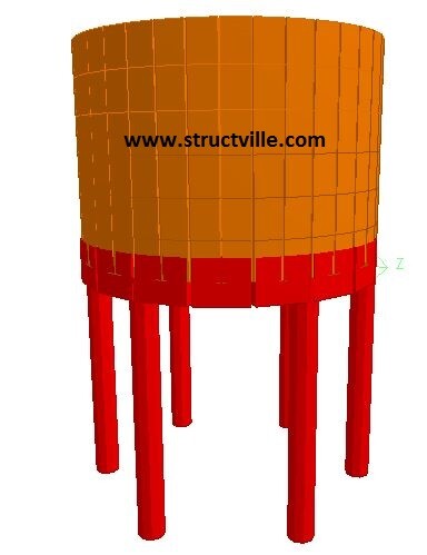
Fig 1: 3D model of cylindrical water tank
Bending moment radial 1
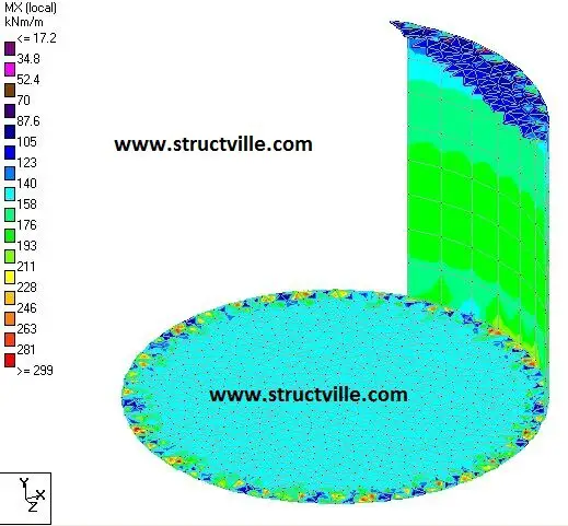
Fig 2: Radial bending moment on the tank shell due to temperature load
Longitudinal bending moment due to temperature difference
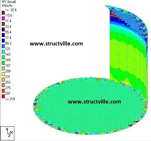
Fig 3: Longitudinal bending moment on the tank shell due to temperature load
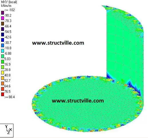
Fig 4: Twisting bending moment on the tank shell due to temperature load
Radial shear
Fig 5: Radial shear on the tank shell due to temperature load
Logitudinal shear
Fig 6: Longitudinal shear on the tank shell due to temperature load
Hoop membrane forces
Fig 7: Hoop tension (membrane) on the tank shell due to temperature load
Vertical axial tension
Fig 8: Longitudinal tension on the tank shell due to temperature load

The differences in internal stresses induced in cylindrical tanks of equal volume and height with the rectangular tank are shown in Table 1.

Table 1: Internal stresses in rectangular and cylindrical tanks due to temperature load

Evaluation of effects of temperature difference in storage tanks using Staad Pro

In some factories and industries, tanks are used for the storage of hot liquids which are used in production. In such scenarios, the temperature inside the tank and the temperature in the surrounding may not be the same. It is well known that internal forces are induced in statically indeterminate structures when there is temperature difference as the elements undergo differential thermal expansion/contraction. For simple frames, the internal forces due to temperature difference can be easily obtained using the force method of structural analysis. But for more complex structures like combination of beams and plates, software like Staad Pro can be used for evaluation of temperature difference.

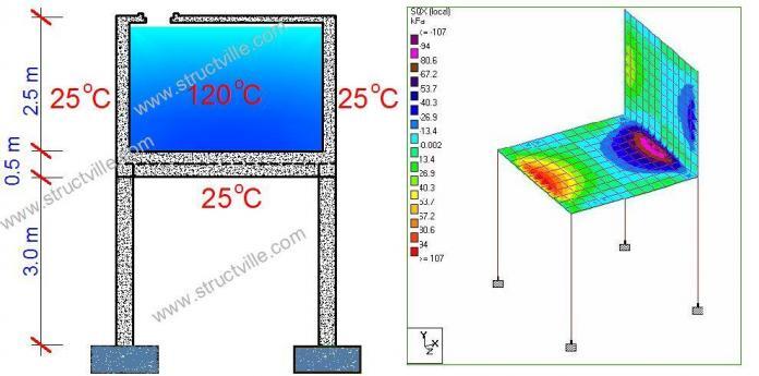
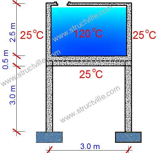
For example, let us consider the reinforced concrete tank with the dimensions shown in Figure 1;

Tank storing hot liquid
Fig 1: Structural scheme of water tank subjected to temperature difference

Dimensions of columns = 300 x 300 mm
Dimension of beams = 300 x 500 mm
Height of column above ground level = 3 m
Length of tank = Width of tank = 3 m (centre to centre)
Height of tank = 2.5 m (centre to centre)
Thickness of tank walls and base = 250 mm
Support condition = Fixed
Temperature inside the tank = 120 oC
Temperature outside the tank = 25 oC
Maximum hydrostatic pressure from the liquid stored = 25 kPa
Modulus of elasticity of concrete = 2.8 x 10⁷ kN/m2
Coefficient of expansion of concrete = 1.0 x 10⁻⁵ /oC

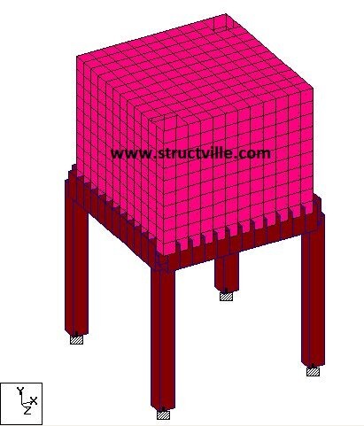
The tank has been modelled on Staad Pro (see Figure 2) using the parameters defined above.

Water tank modelled on Staad
Fig 2: Modelling of the tank on Staad Pro

The walls of the tank were subjected to a triangular hydrostatic pressure distribution of 25 kPa. You can check how apply hydrostatic loads on Staad Pro here. The temperature difference action applied to the the tank is shown below.

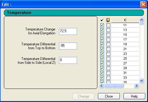
Temperature change for axial elongation = Average temperature = (25 + 120)/2 = 72.5 oC
Temperature difference = 25 – 120 = -95 oC

The application on Staad Pro is shown in Figure 3.

Temperature load on Staad Pro
Fig 3: Application of temperature load on Staad Pro

When analysed on Staad Pro, the results shown in Figures 4-8 were obtained for the tank shells at SLS.

Bending moment due to water pressure 1
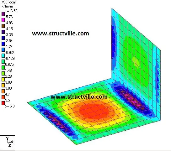
Fig 4: Bending moment on the tank shell due to water pressure
Shear force due to water pressure 1
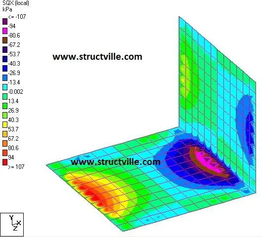
Fig 5: Shear stress on the tank shells due to water pressure
Bending moment due to temperature difference 1
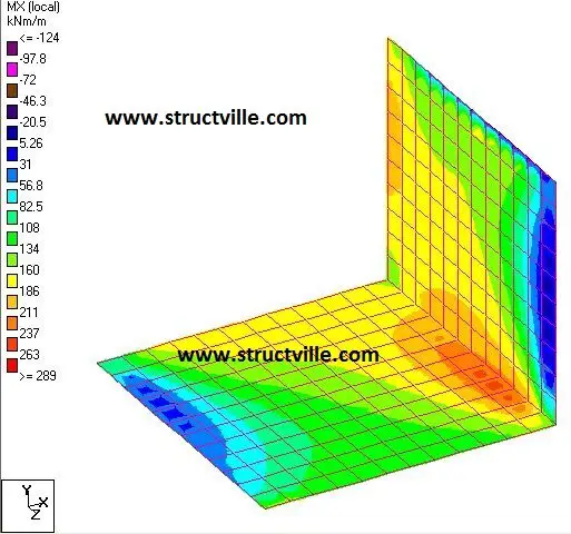
Fig 6: Bending moment on the tank shell due to temperature difference
Shear stress due to temperature difference
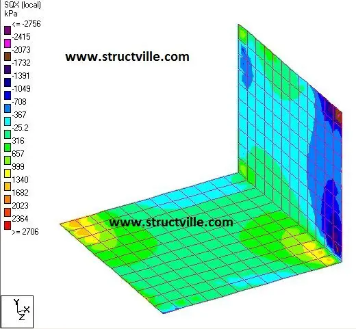
Fig 7: Shear stress on the tank shell due to temperature difference
Displacement due to temperature difference 1
Fig 8: Displacement of tank shell and frame due to temperature difference

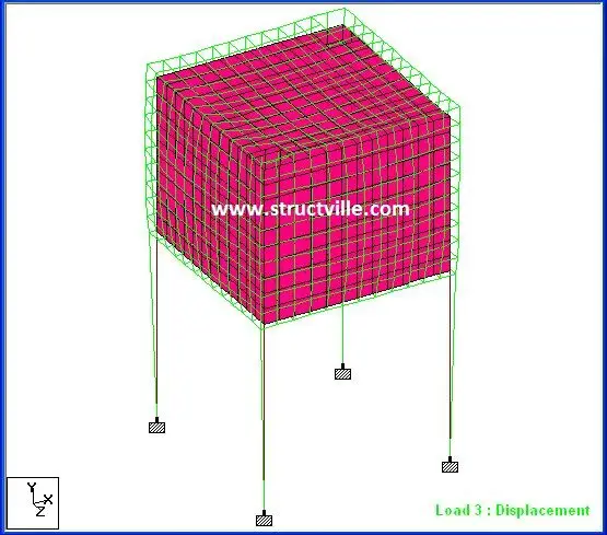
The internal stresses induced in the tank shell due to temperature difference is quite serious and requires detailed attention during design.