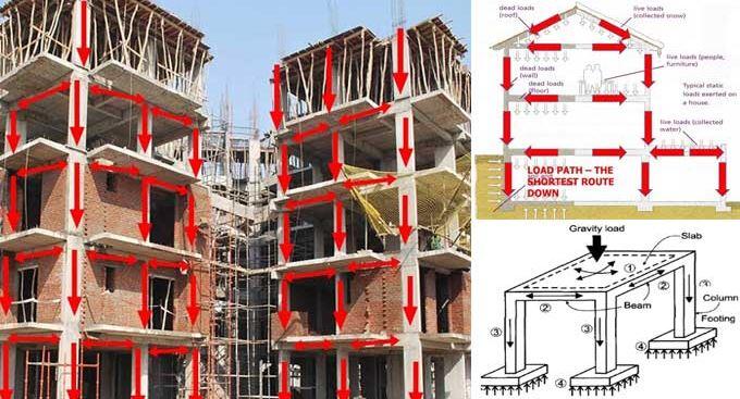
Transfer structures can be described as structural elements that redirect gravity loads (usually from columns or walls) to other structures (such as beams or plates) for distribution to another supporting structure that can resist the load. In other words, transfer structures alter the load path of gravity loads from one alignment to another.
The prominent issue in the design of transfer structures is that the member transferring the load becomes heavily loaded, thereby demanding a very cautious design. Furthermore, the unconventional load path may unintentionally affect the design and performance of other structural members within the building. This is usually found in high-rise buildings where floor arrangements differ. Structural elements such as beams and slabs are often employed as load transfer structures.

Applications of Transfer Structures
Transfer structures play a crucial role in the design and construction of buildings, especially when faced with complex architectural requirements and structural challenges. These structures are engineered to efficiently transfer loads from one area of a building to another, ensuring structural integrity and stability. From tall skyscrapers to large-scale infrastructure projects, transfer structures have become indispensable elements of modern construction.
The primary purpose of transfer structures is to redistribute the loads imposed on them to different vertical and horizontal components of a building. This redistribution of forces is necessary when there are discontinuities or changes in load paths within a structure. Transfer structures enable the efficient transfer of loads from, for example, columns or walls above to columns or walls below, bypassing obstructions such as openings, large spans, or irregular load distributions.
Design of Transfer Structures
I had my first experience in the design of transfer structures in January 2016, when I was given the project to redesign the Cafeteria Hall of Ritman University Community Centre. The original arrangement of the structure is shown in Figure 2;

It was desired to reduce the intermediate columns of the ground floor to a row of single columns as shown in Figure 3. In this case, the beam to support the two rows of internal columns on the first floor can be described as a transfer beam. The two columns so supported can be described as ‘floating columns‘. The transfer beam will be responsible for altering the load path of the internal columns. In some cases, deep beams can be used as transfer structures.

On analysis of the transfer beam, I observed a heavy shear force within the intermediate support, which lead to an increase in the depth of the beam, and the provision of heavy longitudinal and shear reinforcement within the region. This modified arrangement is an example of a transfer structure in its simplest term. The floor beam carrying those upper columns could be described as a transfer beam.
Transfer structures should be designed by experienced engineers, especially those who have practical site experience and a very good understanding of the statics of structures. This is mainly because the design of reinforced concrete transfer structures demands that the engineer will manipulate the depth, width, and reinforcements being provided by the design software.
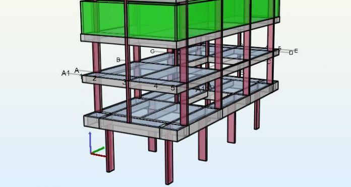
For example, the 5-storey building (G+4) shown below was analysed and designed using Orion Software. The building is a typical transfer structure wherein all the ground floor columns are terminated on the first floor. The rest of the columns started from the first floor and go all the way to the roof. The upper columns are supported on 1.5m long cantilever beams (overhangs) wrapping around the building at the first-floor level (see Figure 4).
For the design of the structure, an initial trial depth of 600 mm was considered for all the first-floor beams and a beam width of 230 mm. The preliminary section failed in flexure and shear as expected for a 5-storey building.
Subsequently, the depth was increased to 750 mm while maintaining the same width of 230 mm. Most of the spans started looking okay (especially for the internal longitudinal/transverse beams), but the cantilever regions were still failing in shear. At this point, the width of the cantilever regions was increased to 300 mm.
Note: The idea is that when it is certain that a beam is adequate in bending (flexure), the width can be increased in order to reduce the shear stress instead of increasing the depth. However, adequate care must be taken about the detailing and architectural requirements.
At the end of the design and manipulation, the depth and width of the beam that satisfied the ultimate limit state requirements were 900 mm and 400 mm respectively, especially for the cantilever regions. The perimeter beams of the first floor were okay at a depth of 600 mm and width of 230 mm, but in order to avoid any awkward appearance of the building, the depth of the perimeter beams was also taken to 900 mm.
In summary, one of the major issues of transfer structures is shear, and more often than not, you will require more than two legs of reinforcement with very close spacing. It is sometimes recommended that the strut-and-tie method is better for the analysis of transfer beams, especially when it is a deep beam.
Furthermore, architects should bear these challenges in mind when designing buildings that may demand the need for transfer structures by increasing the headroom of the building. When the headroom is high enough, there is enough flexibility for proper design by manipulating the width and depth of the beams as appropriate. The suspended ceiling can drop below beams in order to have a flat ceiling finish that will conceal the irregularities of the beam geometry.
Moreover, it is also important that the design engineer keep formwork (cost, construction, reusability) in mind while manipulating section dimensions. The more uniform the sections, the more economical and easier the building becomes for the owner and the builder.
See the images below for some of the structural details for the beams as produced by Orion (unedited).
Note that for bar mark 59 above, you can change the 7H25 to 2 layers
Note that there will be a need for sidebars since the depth of the beam is 900 mm. Thank you for visiting Structville today and God bless you.
Do you know that you can partner with Structville to champion infrastructure development in Africa? Send an e-mail to info@structville.com for more information.


Orion most times if not always provide sidebars.
Even on your detailed pics.
Orion clearly showed it in fig 3
2x3H16-81-200
You did a great job.
Orion is a great software although it has some limitations unlike Etabs and co. It's details are good too. I make good use of it and perfectly.
You are right.
• I liked the way you wrote the article. It was very straightforward and your knowledge on the subject is fantastic.Shop Drawings Preparation in India
Fabrication Drawings preparation in India
MEP F modelling in India
Interference Analysis in India
COBie adaptation in India
Construction Documentation in India
EIWAA Group provides Engineering Consultancy in UAE & Structural Design Consultancy in UAE to clients across the UAE
Can an upstand beam be used as a transfer beam of a structure of G+1 floors?
Yes it can be used
Hi there,
you are doing a great job, how do you deal with transfer slabs? A situation where a cantilever flat slab needs to carry 2 suspended floors.