The higher a building goes, the higher the effects of lateral forces such as the wind on the structure become. Shear walls are often used for providing lateral stability against destabilising actions of wind in reinforced concrete structures. Shear walls can be independently relied on to provide lateral stability in a building, or sometimes other elements such as beams, columns, and staircases can interact with shear walls to provide the required lateral stiffness to a building.
Shear-wall frame interaction for resisting lateral forces is usually complex and may involve tedious manual calculations. However, this can be made simple by using finite element analysis software. It is however easy to transfer wind load manually to shear walls without recourse to the columns. This is the concept that this article explores.
Read Also…
Analysis of Coupled Shear Wall Under the Effect of Wind Load
Calculation of the natural frequency of multistorey frames
To determine the wind load transferred to shear walls in a building, the load is divided among the stabilising elements based on their stiffness (second moment of area). The stiffer elements attract a greater portion of the load. If the shear walls and other stabilising elements are symmetrically arranged (which is recommended), the centre of gravity and the shear centre (centre of stiffness) coincides and eliminate any potential torsion (twisting) in the building due to the lateral load. However, if the arrangement is unsymmetrical, there will be a twisting moment in the structure that must be properly accounted for in the design.
Let us use an example to show how this is done. Consider the general arrangement of a 7-storey building shown below;
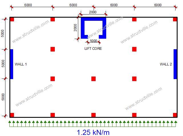
The characteristic wind pressure coming from the y-direction to the building is 1.25 kN/m2. The thickness of the shear walls and the lift core is 225 mm. Let us distribute the wind load to the stabilising elements of the building (shear walls and lift core).
The relative stiffness of the elements are as follows;
Moment of inertia
Wall 1 = Wall 2 = Iw1,x = Iw2,x =bh3/12 = (0.225 x 53)/12 = 2.34 m4
Lift core = IL,x = (2 x 23)/12 – (1.55 x 1.553)/12 – (1.0 x 0.2253)/12 = 0.851 m4
∑Ix = 2Iw,x + IL,x = 2(2.34) + 0.851 = 5.531 m4
The ratio of wind force transferred to each wall (wall 1 and wall 2) = Iwi,x/∑Ix = 2.34/5.531 = 0.423
Therefore each wall will carry 42.3% of the wind force. This implies that about 85% of the wind force is resisted by the shear wall, while the remaining 15% is resisted by the lift core.
To calculate the shear centre of the structure, the following procedure can be followed;
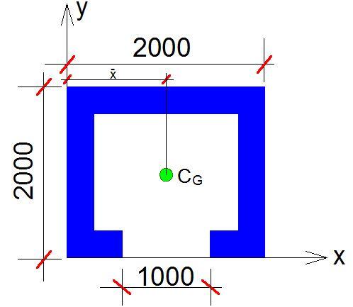
We will need to determine the centre of gravity of the lift core. We can easily form a table for that;
| Area A (m2) | Lever arm (x) m | Ax (m3) | |
| 2.0 x 2.0 | 4 | 1.0 | 4 |
| -1.55 x 1.55 | -2.4 | 1.0 | -2.4 |
| -1.0 x 0.225 | -0.225 | 1.0 | -0.225 |
| ∑A = 1.375 m2 | ∑Ax = 1.375 m2 |
Therefore the centre of gravity in the x-direction is ∑Ax/∑A = 1.0 m
Taking moment about the centreline of wall 2;
(Iw1,x × 24) + (IL,x × 12) = dx∑Ix
(2.34 × 24) + (0.851 × 12) = (dx × 5.531)
Therefore, dx = 12 m = L/2 = 12 m
This shows that in the direction considered, the shear centre coincides with the centroid of the building, hence no torsion. Had there been significant torsion this would have been resolved into +/– forces in a couple based on the shear walls.
The force on each shear wall is therefore as follows;
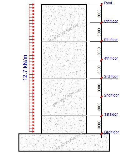
wk1 = wk2 = 0.423 x 1.25 x 24 = 12.69 kN/m




Excellent information.