For a tall building to be successful, at a minimum, the structure should employ systems and materials appropriate to the building’s height and configuration. The structural system for a tall building must perform well and lend itself to efficient construction [1]. According to [1], a successful tall building should have the following features;
- Create a friendly and inviting image that has positive values to building owners, users, and observers.
- Fit the site, providing proper approaches with a congenial layout for people to live, work, and play.
- Be energy-efficient, providing interior space with a controllable climate.
- Allow flexibility in office layout with easily divisible space.
- Offer space oriented to provide the best views.
- Most of all, the building must make economic sense, without which none of the development would be a reality.
In the year 1969, Fazlur Khan classified structural systems for tall buildings relating to their heights with considerations for efficiency in the form of “Heights for Structural Systems” diagrams [2]. This marked the beginning of a new era of skyscraper revolution in terms of multiple structural systems [3].
Later, Khan upgraded these diagrams by way of modifications [4, 5]. He developed these schemes for both steel and concrete as can be seen from Figures 1 and 2 respectively [6]. Khan argued that the rigid frame that had dominated tall building design and construction so long was not the only system fitting for tall buildings.
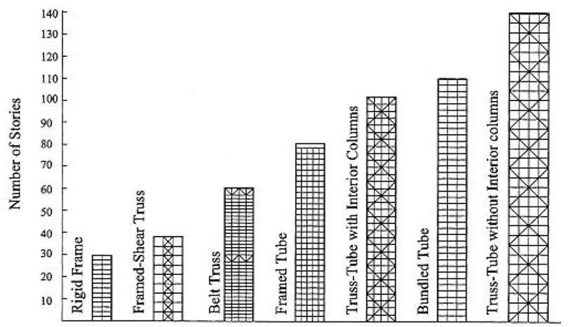
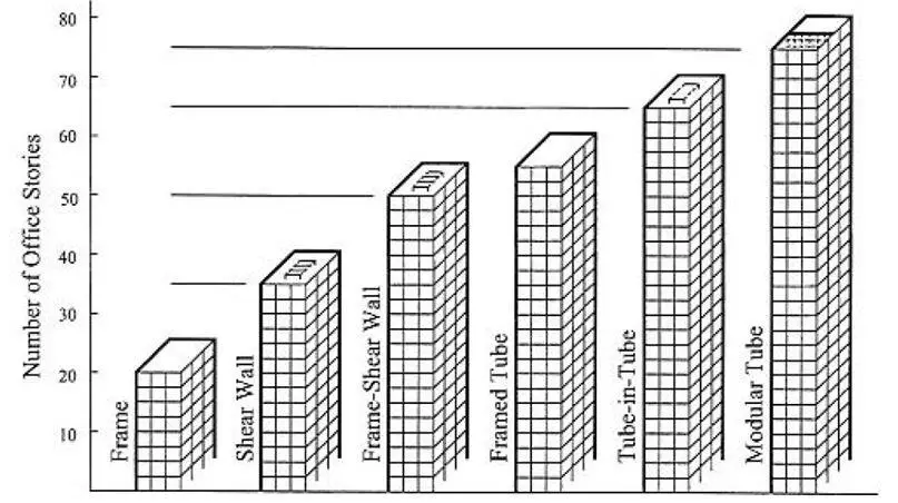
Bungale [1] also presented a table to show the appropriate structural system for reinforced concrete tall buildings. This is shown in Table 1.
Table 1: Appropriate structural systems for concrete tall building [1]
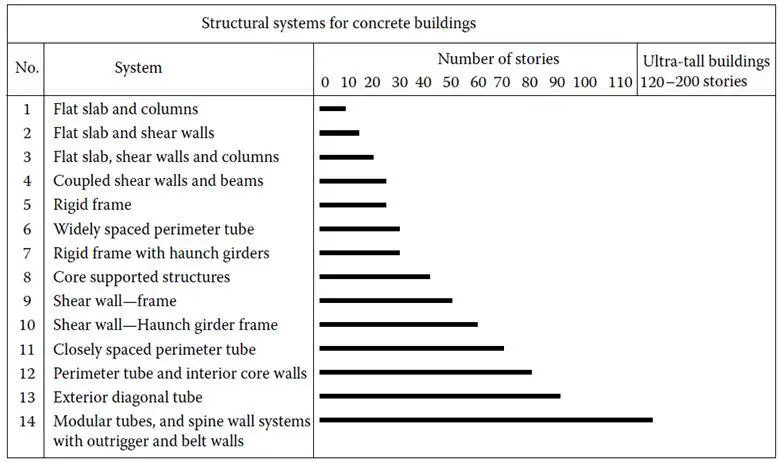
We are going to give a brief description of the various and popular structural systems for tall buildings in the sub-sections below. The structural system to be adopted in any design should be able to carry different types of loads, such as gravity, lateral, temperature, blast and impact loads. The drift of the tower should be kept within limits, such as H/500.
The structural systems usually adopted for high rise buildings are as follows;
Column and slab systems
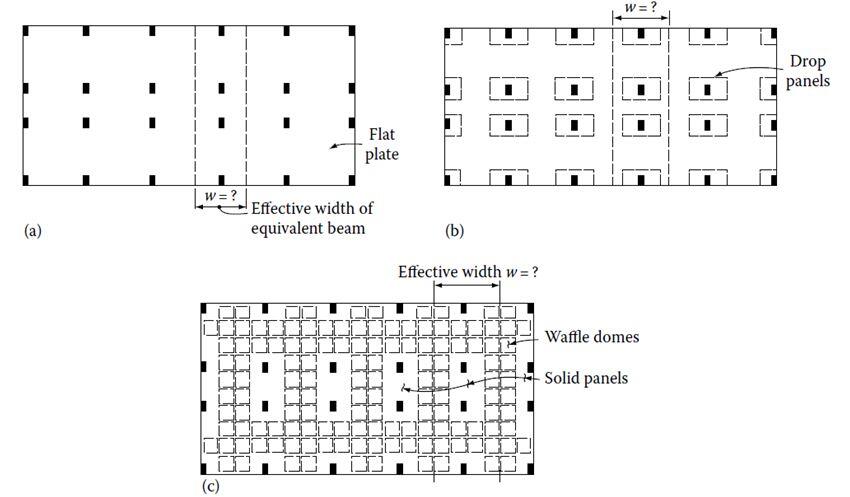
Concrete floors in tall buildings often consist of a two-way floor system such as a flat plate, flat slab, or a waffle system which can resist lateral loads (see Figure 3). In a flat plate system, the floor consists of a concrete slab of uniform thickness which frames directly into the columns. Two way flat slabs make use of either capitals in columns or drop panels in slab or both, requiring less than a flat plate because extra concrete is provided only at columns where the shears and moments are the greatest.
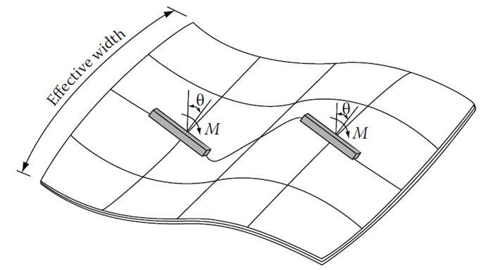
The waffle system is obtained using rows of joists at right angles to each other; the joists are commonly formed by square domes (see Figure 4). The domes are omitted around the columns to increase the moment and shear capacity of the slab [7]. Any of the three systems can be used to function as an integral part of the wind-resisting systems for buildings in the 10 to 20 storey range. The concept of an “effective width” is usually used in the analysis of such buildings subjected to lateral forces.
Rigid Frames
A rigid frame is characterized by the flexure of beams and columns and rotation at the joints. Interior rigid frames for office buildings are generally inefficient because;
(1) The number of columns in any given frame is limited due to leasing considerations and
(2) The beam depths are often limited by the floor-to-floor height.
However, frames located at the building exterior do not necessarily have these limitations. An efficient frame action can thus be developed by providing closely spaced columns and deep spandrels at the building exterior. A rigid-frame high-rise structure typically comprises of parallel or orthogonally arranged bents consisting of columns and girders with moment-resistant joints [8].
The continuity of the frame also increases resistance to gravity loading by reducing the positive moments in the girders [1]. The advantages of a rigid frame are the simplicity and convenience of its rectangular form. Its unobstructed arrangement, clear of structural walls, allows freedom internally for the layout and externally for the fenestration.
Rigid frames are considered economical for buildings of up to about 25 stories, above which their drift resistance is costly to control. If, however, a rigid frame is combined with shear walls, the resulting structure is very much stiffer so that its height potential may extend up to 50 stories or more [1].
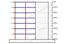
The horizontal stiffness of a rigid frame is governed mainly by the bending resistance of the girders, the columns, and their connections, and in a tall frame, also by the axial rigidity of the columns (see Figure 5). The accumulated horizontal shear above any story of a rigid frame is resisted by shear in the columns of that story.
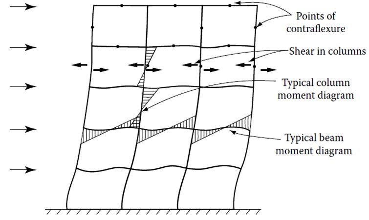
Rigid frame systems are not efficient for buildings over 30 storeys in height because the shear racking component of deflection caused by the bending of columns and girders causes the building to sway excessively [3].
Braced frames are a type of moment-resisting frames that have single diagonal x-braces and k-braces. Lattice and knee bracing are also used. Concrete braced frames are often not used, since shear walls are superior for construction and lateral resistance. Lattice bracing is used in pre-cast panel construction.
Steel braced frames are used in interior cores, so connections could easily be made with wall panels. Composite braced frames may have steel bracings in concrete bracings in steel frames. Concrete encasement of columns and composite floor beams has also been used.
Shear wall-Frame Systems
In this system, resistance to horizontal loading is provided by a combination of shear walls and rigid frames [9]. The shear walls are often placed around elevator and service cores while the frames with relatively deep spandrels occur at the building perimeter. When a wall–frame structure is loaded laterally, the distinctly different deflected forms of the walls and the frames can be quite effective in reducing the lateral deflections to the extent that buildings of up to 50 stories or more are economical [1].
The potential advantages of a wall–frame structure depend on the intensity of horizontal interaction, which is governed by the relative stiffness of the walls and frames, and the height of the structure. The taller the building and the stiffer the frames, the greater the interaction [10].
The interaction of frame and shear walls has been understood for quite some time, the classical mode of the interaction between a prismatic shear wall and a moment frame is that the frame basically deflects in a so-called shear mode while the shear wall predominantly responds by bending as a cantilever (see Figure 6).
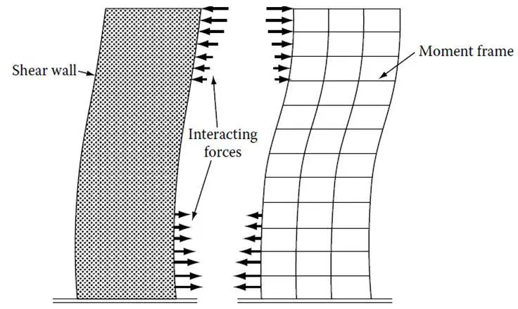
Compatibility of horizontal deflection introduces an interaction between the two systems which tends to impose a reverse curvature in the deflection pattern of the system. The combined structural action, therefore, depends on the relative rigidities of different elements used in the makeup of the lateral-load-resisting system.
The distribution of total wind shear to the individual shear walls and frames as given by the simple interaction diagram is valid only if one of the following two conditions is satisfied.
1. Each shear wall and frame must have constant stiffness properties throughout height of the building.
2. If stiffness properties vary over the height, the relative stiffness of each wall and frame must remain unchanged throughout the height of the building.
Shear Truss-Outrigger Braced Systems
The structural arrangement for this system consists of a main concrete core connected to exterior columns by relatively stiff horizontal members such as one or two-story deep walls commonly referred to as outriggers. The core may be centrally located with outriggers extending on both sides or it may be located on one side of the building with outriggers extending to the building columns on one side [1].
The outrigger system is a development due to the desire to make inner cores and outer columns as one by linking them together at one or more levels with rigid arms – outriggers. It may be formed by any combination of steel, concrete or composite construction and reduce the structure’s internal overturning moment by up to 40 % compared to that of a free cantilever [10].
Multilevel outrigger systems can provide up to five times the moment resistance of a single outrigger system. Outrigger systems have been used for buildings up to 70 stories but the concept should hold for even higher buildings [11].
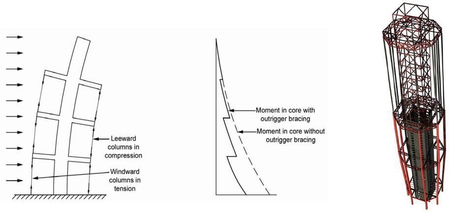
The basic structural response of the system is quite simple. When subjected to lateral loads, the column-restrained outriggers resist the rotation of the core, causing the lateral deflections and moments in the core to be smaller than if the freestanding core alone resisted the loading as shown in Figure 7 [3].
The external moment is resisted not by bending of the core alone, but also by the axial tension and compression of the exterior columns connected to the outriggers. As a result, the effective depth of the structure for resisting bending is increased when the core flexes as a vertical cantilever, by the development of tension in the windward columns, and by compression in the leeward columns.
Framed-Tube System
In its simplest terms, a framed tube can be defined as a three-dimensional system that engages the entire building perimeter to resist lateral loads [1]. A necessary requirement to create a wall-like three-dimensional structure is to place columns on the building exterior relatively close to each other, joined by deep spandrel girders as shown in Figure 8.
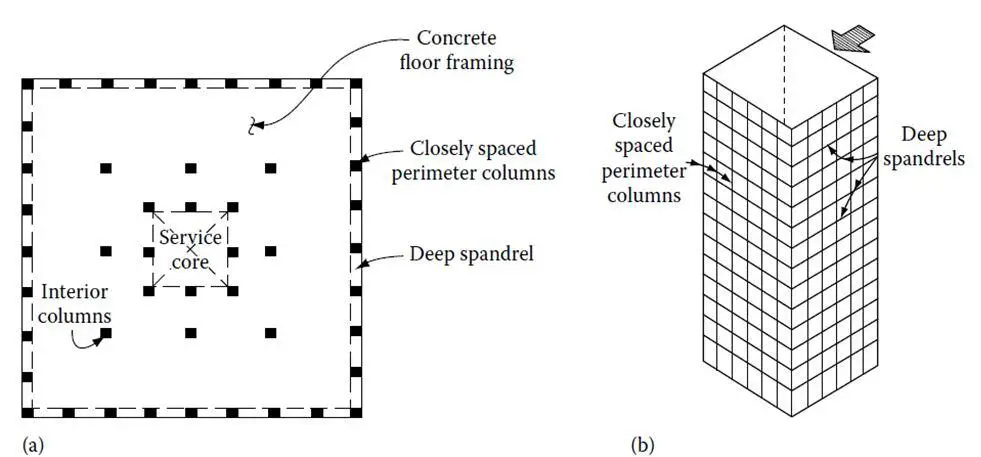
The system works quite efficiently as a hollow vertical cantilever. However, lateral drift due to the axial displacement of the columns—commonly referred to as chord drift—and web drift, caused by shear and bending deformations of the spandrels and columns, may be quite large depending upon the tube geometry.
In framed tube systems, the “strong” bending direction of the columns is typically aligned along the face of the building, in contrast to a typical transverse rigid frame where it is aligned perpendicular to the face. The frames parallel to the lateral load act as webs of the perforated tube, while the frames normal to the load act as the flanges.
When subjected to bending, the columns on opposite sides of the neutral axis of the tube are subjected to tensile and compressive forces. In addition, the frames parallel to the direction of the lateral load are subjected to the in-plane bending and the shearing forces associated with an independent rigid frame action.
Trussed Tube Systems
A trussed tube system improves the efficiency of the framed tube by increasing its potential for use in taller buildings and allowing greater spacing between the columns. This is achieved by adding diagonal bracing at the faces of the tube as shown in Figure 9 to virtually eliminate the shear lag in both the flange and web frames [1].
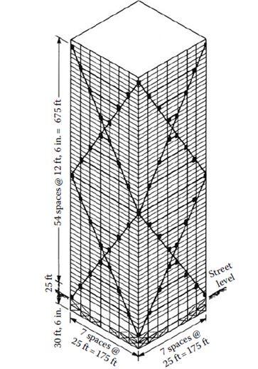
The framed tube, as discussed previously, even with its close spacing of columns is somewhat flexible because the high axial stresses in the columns cannot be transferred effectively around the corners. For maximum efficiency, the tube should respond to lateral loads with the purity of a cantilever, with compression and tension forces spread uniformly across the windward and leeward faces.
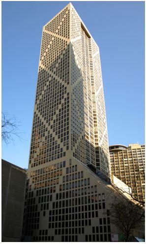
The framed tube, however, behaves more like a thin-walled tube with openings. The axial forces tend to diminish as they travel around the corners, with the result that the columns in the middle of the windward and leeward faces may not sustain their fair share of compressive and tensile forces. An example of an application is the Onterie Centre building in Chicago (Figure 10).
Bundled Tube Systems
The bundled tube structure consists of four parallel rigid frames in each orthogonal direction, interconnected to form nine bundled tubes (see Figure 11). The principle is the same as for the single tube structure where the frames in the horizontal load direction act as webs and the perpendicular frames acts as flanges.
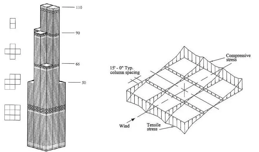
By introducing the internal webs the shear lag is drastically reduced and as a result the stresses in the columns are more evenly distributed and their contribution to the lateral stiffness is more significant. This allows for the columns to be spaced further apart and to be less striking. In essence, the underlying principle to achieve a bundled tube response is to connect two or more individual tubes into a single bundle. The main purpose is to decrease shear lag effects.
References
[1] Bungale S. T. (2010): Reinforced Concrete Design of Tall Buildings. CRC Press, Taylor and Francis Group
[2] Khan, F.R. (1969): Recent structural systems in steel for high-rise buildings. In Proceedings of the British Constructional Steelwork Association Conference on Steel in Architecture. London: British Constructional Steelwork Association.
[3] Ali M.M., and Moon K.S. (2007): Structural developments in tall buildings: Current trends and future prospects. Architectural Science Review 50(3):205-223
[4] Khan, F.R. (1972): Influence of design criteria on selection of structural systems for tall buildings, In Proceedings of the Canadian Structural Engineering Conference. Toronto: Canadian Steel Industries Construction Council, 1-15.
[5] Khan, F.R. (1973): Evolution of structural systems for high-rise buildings in steel and concrete. In J. Kozak (Ed.), Tall Buildings in the Middle and East Europe: Proceedings of the 10th Regional Conference on Tall Buildings-Planning, Design and Construction. Bratislava: Czechoslovak Scientific and Technical Association
[6] Ali, M.M. (2001): Art of the Skyscraper: The Genius of Fazlur Khan. New York: Rizzoli.
[7] Reddy S.V.B., and Eadukondalu M. (2018): Study of the lateral structural systems in tall buildings. International Journal of Applied Engineering Research 13(15):11738 – 11754
[8] Zalka K. A. (2013): Structural Analysis of Regular Multi-storey Buildings. CRC Press – Taylor and Francis Group, USA
[9] Aginam C.H., Chidolue C.A., and Ubani O.U. (2015): Effect of Planar Solid shear wall-frame arrangement on the deformation behaviour of multi-story frames. IOSR Journal of Mechanical and Civil Engineering 12(1):98-105
[10] Sandelin C. and Bujadev E. (2013): The stabilization of high-rise buildings: An evaluation of the tubed mega frame concept. Dissertation submitted to the Department of Engineering Science, Applied Mechanics, Civil Engineering, Uppsala University
[11] Hallebrand E., and Jakobsson W. (2016): Structural design of high-rise buildings. M.Sc thesis presented to the Department of Construction Sciences (Division of structural mechanics), Lund University, Sweden




excellent article Truly a lot of information the way you divided the information is superb a really great read