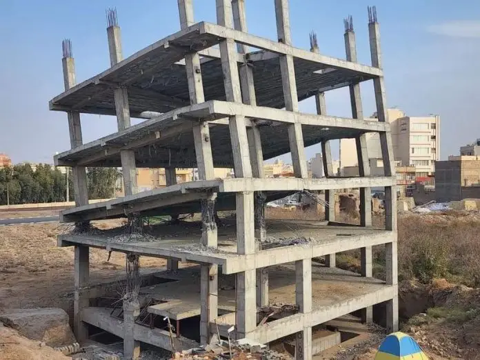
Internal stresses are induced in statically indeterminate frames when one support settles relatively to another. This is one of the major detrimental effects of differential settlement in civil engineering structures, and it is capable of inducing cracks and structural failures in buildings. Therefore, wherever it matters or where it is anticipated, the effects of the differential settlement must be taken into account during the design of civil engineering structures.
In this article, an indeterminate frame whose support has been subjected to an indirect action of differential settlement has been presented and fully solved. As stated above, if any statically indeterminate structure experiences differential settlement of supports, internal stresses will be developed in the members of the structure.
Analysis of such structures may be effectively performed by the force (flexibility) or stiffness (displacement) method in canonical form. In the paper downloadable in this article, the frame loaded as shown below is subjected to a differential settlement of 25mm at fixed support A. The internal stresses induced were calculated using the force method, stiffness method, and slope deflection method.
Canonical Equations
Consider a structure that is unable to be solved solely based on equilibrium equations (statically indeterminate). This structure has additional constraints (redundant constraints) that number “n.” Additionally, certain supports of this structure can undergo linear or angular movements (displacements) denoted by “di.”
The following set of equations are known as the Canonical equations and will be used to analyze this structure:
δ11X1 + δ12X2 + … + δ1nXn + δ1∆ = 0
δ21X1 + δ22X2 + … + δ1nXn + δ2∆ = 0
. . . . . . . . . . . . . . . . . . . .
δ31X1 + δ32X2 + … + δ3nXn + δ3∆ = 0
where free terms δk∆ (k = 1, 2,…, n) represent displacements of the primary system in the direction of primary unknowns Xk due to settlements of the supports. For the calculation of these terms, we need to use the theorem of reciprocal unit displacements and reactions (Rayleigh’s second theorem). This is given by;
δi∆ = -EIC (∆.R)
Where:
EIC = Flexural rigidity of the column
∆ = Settlement at the point under consideration
R = Support reaction at the point under consideration
Steps in the Analysis of Structures Due to Sinking of Supports
This section outlines the step-by-step procedure for analyzing redundant structures experiencing support settlements:
1. Kinematics and Redundancy Determination:
- Carry out a kinematic analysis of the structure.
- Identify the degree of redundancy (number of redundant constraints, n).
- Select a primary system based on the force method.
- Formulate the canonical equations using the chosen primary unknowns (Xi).
2. Unit Load Analysis:
- Construct unit bending moment diagrams for each redundant member.
- Calculate the unit displacements (δi) corresponding to each redundant constraint (di).
3. Free Term Calculations:
- Determine the free terms within the canonical equations, considering the external loading and support settlements.
4. Solving for Primary Unknowns:
- Solve the system of canonical equations with respect to the primary unknowns (Xi).
5. Internal Force Determination:
- Construct the internal force diagrams (axial forces, shear forces, bending moments) for all members using the obtained primary unknowns (Xi) and the principle of superposition.
6. Support Reaction Verification:
- Calculate the reactions at all supports using equilibrium equations and the internal forces.
- Verify the calculated support reactions through equilibrium checks.
Worked Example
The portal frame shown below is fixed at column base A, and hinged at point C as shown below. The column of the frame has a square cross-section of 30cm x 30cm while the beam has a depth of 60cm and a width of 30cm. The foundation of support A settles vertically by 25mm. Draw the bending moment, shearing force, and axial force diagram due to the differential settlement action on the frame (E = 2.17 × 10⁷ kN/m2).
SOLUTION
Geometrical properties
Moment of inertia of column IC = (bh3) / 12 = (0.3 × 0.33)/12 = 6.75 × 10⁻⁴ m4
Moment of inertia of beam IB = (bh3) / 12 = (0.3 × 0.63)/12 = 5.4 × 10⁻³ m4
We desire to work in terms of IC such that IC/IB = 0.125
Hence flexural rigidity of the column, EIC = (2.17 × 107) × (6.75 × 10-4) = 14647.5 KN.m2
The deformation of a structure at a point due to support settlement is given by;
δi∆ = -EIC (∆.R) ———— (1)
Where;
EIC = Flexural rigidity of the column
∆ = Settlement at the point under consideration
R = Support reaction at the point under consideration
Basic system
The next step in the analysis is to reduce the structure to a basic system, which is a system that must be statically determinate and stable. The frame is statically indeterminate to the second order, which means that we are going to remove two redundant supports.
The degree of static indeterminacy (RD) is given by;
RD = (3m + r) – 3n – s ————————— (2)
So that RD = (3 × 2) + 5 – (3 × 3) – 0 = 2
By choice, I am deciding to remove the two reactive forces at support C of the frame to obtain the basic system as shown in Figure 1.2 below;
Analysis of Case 1;
X1 = 1.0, X2 = 0
The simple static analysis of the structure with case 1 loading is shown below in terms of the internal stresses diagram. Realise that there is a unit value support reaction acting at support A (pointed downwards) and a bending moment of 5.0 units.
Analysis of Case 2;
X1 = 0, X2 = 1.0
The simple static analysis of the structure loaded with case 1 loading is shown below in terms of the internal stresses diagram. It will be so important to realise that there is no vertical support reaction at point A. A unit horizontal reaction is developed at the support to counter the applied unit load for case 2.
The appropriate canonical equation for this structure is therefore;
δ11X1 + δ12X2 + δ1∆ = 0
δ21X1 + δ22X2 + δ2∆ = 0
Computation of the influence coefficients
Influence coefficients are based on Mohr’s integral such that δi = 1/EI∫Mmds.
We can compute this by using the graphical method (making use of bending moment diagrams), we directly employ Vereschagin’s rule which simply states that when we are combining two diagrams of which one must be of a linear form (due to the unit load) and the other of any other form, the equivalent of Mohr’s integral is given by the area of the principal combiner (diagram of arbitrary shape) multiplied by the ordinate which its centroid makes with the linear diagram. The rule can also work vice versa. This process has been adopted in this work.
Where;
EI = Flexural Rigidity of the section
M = Bending moment due to externally applied load
̅M = Bending moment due to unit load at the point where the deflection is sought
READ ALSO IN THIS BLOG…
Elaborate Formulation of Diagram Combination Equations According to Vereschagin’s Rule
Example on Analysis of Statically Determinate Frames (Part 2)
δ11 (Deformation at point 1 due to unit load at point 1)
This is obtained by the bending moment of case 1 combining with itself. This is shown below.
EICδ11 = (5 × 5× 4) + (1/3 × 5 × 5 × 5 × 0.125) = 105.208
δ21 = δ12 (Deformation at point 2 due to unit load at point 1 which is equal to deformation at point 1 due to unit load at point 2 based on Maxwell-Betti’s law). This is obtained by the bending moment diagram of case 1 combined with the bending moment diagram of case 2. This is shown below.
EICδ21 = (1/2 × 5 × 4 × 4) = 40
δ22 (Deformation at point 2 due to unit load at point 2)
This is obtained by the bending moment diagram of case 2 combining with itself. This is shown below.
EICδ11 = (1/3 × 4 × 4 × 4) = 21.333
Influence coefficients due to support settlement
Case 1
(Take a good look at the support reactions)
δi∆ = -EIC(∆.R)
R = Support reaction at point A = -1.0
∆ = Support settlement in the direction of support reaction = -25 mm = -0.025m
Hence δ1 ∆ = – 14647.5 × (-1 × -0.025) = -366.1875
Case 2
(Take a good look at the support reactions again)
Horizontal support reaction at point A = R = 1.0
∆ = Support settlement/movement in the direction of support reaction = 0
Hence δ2∆ = 0
The appropriate canonical equation now becomes;
105.208X1 + 40X2 = 366.187
40X1 + 21.333X2 = 0
On solving the simultaneous equations;
X1 = 12.123 kN
X2 = -22.730 kN
The final value of the internal stresses is given by the equations below;
Mdef = M1X1 + M2X2
Qdef = Q1X1 + Q2X2
Ndef = N1X1 + N2X2
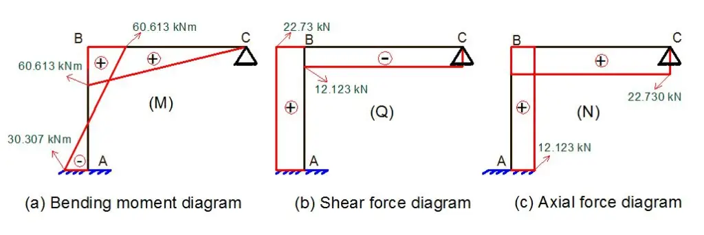
Final Bending Moments (Mdef)
MA = (12.1226 × 5) + (-22.73 × 4) = -30.307 kNm
MB = (12.123 × 5) = -60.613 kNm
MC = hinged support = 0
Final Shear Force (Qdef)
QA – QBB = (-22.73 × -1) = 22.73 kN
QBR – QCL = (12.123 × -1) = -12.123 kN
Final Axial Force (Ndef)
NA – NBB = (12.123 × 1) = 12.123 kN
NBR – NCL = (-22.73 × -1) = 22.730 kN

To download the full calculation sheet and see how the force method is compared with stiffness methods, click HERE
For more analysis and interesting posts, like our Facebook page by clicking www.facebook.com/structville


