Many civil engineering projects usually involve excavating into water-bearing soil formations. Before beginning such excavations, the proper system(s) for managing and controlling groundwater and surface water run-off should be planned. This can only be done in practice if you are aware of the ground and groundwater conditions you are likely to face through site investigation data.
It is necessary to take precautions to manage groundwater flows and pore water pressures in water-bearing soils in order to prevent problematic circumstances during excavation and construction. Effective management of surface water runoff is also necessary. Understanding the potential effects of an excavation can help determine which groundwater control measures are required to assure stability.
There are three groups of methods available for temporary works control of groundwater:
(a) Lowering groundwater levels in construction by means of water abstraction, in other words – groundwater lowering or dewatering.
(b) Exclusion of groundwater inflow to the area of construction by some form of very low permeability cut-off wall or barrier (e.g. sheet-piling, diaphragm walls, artificial ground freezing).
(c) Application of fluid pressure in confined chambers such as tunnels, shafts and caissons to counterbalance groundwater pressures (e.g. compressed air, earth pressure balance tunnel boring machines).
Groundwater Control Techniques
Techniques for the control of groundwater can be divided into two principal types:
(a) Those that exclude water from the excavation (known as exclusion techniques)
(b) Those that deal with groundwater by pumping (known as dewatering techniques)
Exclusion Methods of groundwater control
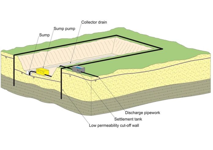
The aim of groundwater control by exclusion is to prevent groundwater from entering the working area. Creating a physically impermeable cut-off wall or barrier around the perimeter of the excavation to keep groundwater out is one of the most widely used exclusion methods. The cut-off often produces a basal seal for the excavation by penetrating vertically down to a very low permeability stratum.

The depth and make-up of any underlying permeable stratum have a significant impact on the costs and viability of constructing a physical cut-off wall. Base instability is possible when upward seepage occurs beneath the base of the cut-off wall due to the lack of or presence of a sufficient very low permeability layer. In these situations, dewatering techniques and exclusion techniques may be combined.
As an alternative, a horizontal barrier or “floor” might be formed adjacent to the cut-off structure to stop vertical seepage. Although it is not common, horizontal barriers have been built utilizing techniques such jet grouting, mix-in-place grouting, and artificial ground freezing.
A portion of the groundwater will become trapped inside the working area if a complete physical cut-off is established. In order to move further with the project, this must be removed, either by sump pumping during excavation or by pumping from wells or wellpoints beforehand.
The capacity of the exclusion technique to enable work to be carried out below the groundwater level with little impact on groundwater levels outside the site is one of its attractive features. This ensures that any groundwater-lowering problems are prevented. Exclusion techniques are frequently employed instead of dewatering techniques, especially in metropolitan areas, to reduce the danger of settlement damage brought on by reducing groundwater levels.
However, it is crucial to remember that practically all walls will leak to some degree when considering the use of the exclusion technique to prevent groundwater level from dropping in areas beyond the site. Particularly vulnerable to leakage are any joints (between columns, panels, piles, etc.) left behind from the installation process.
Several issues can arise if groundwater leaks through cut-offs into the excavation or work area:
(i) The seepages may hinder site operations during construction, necessitating the deployment of sump pumps or surface water management techniques to keep the working area dry.
(ii) The risk of settlement or other negative impacts may result from the leaking into the excavation being severe enough to locally lower groundwater levels outside the site.
(iii) If the cut-offs are a permanent construction, like the walls of a deep basement, even tiny seepages over time will be ugly and could interfere with any architectural finishes that have been applied to the walls.
Grouting or other treatments can frequently be used to address the major seepages that cause issues (i) and (ii). On the other hand, it might be quite challenging to stop or stop the little seepages of (iii). Costs significantly increase if a completely dry or leak-proof construction is required. If cut-off walls are going to be included in the permanent works, this is something that needs to be taken into account.
The techniques used in groundwater exclusion are listed below;
Steel Sheet Piling
In this groundwater control technique, steel sheet piles are driven into the soil to form a barrier against the intrusion of groundwater into the construction area. This is one of the most prominent techniques used in the construction of cofferdams. This technique is applicable to most open soils, however, it can be challenging when obstructions such as rock boulders are encountered.
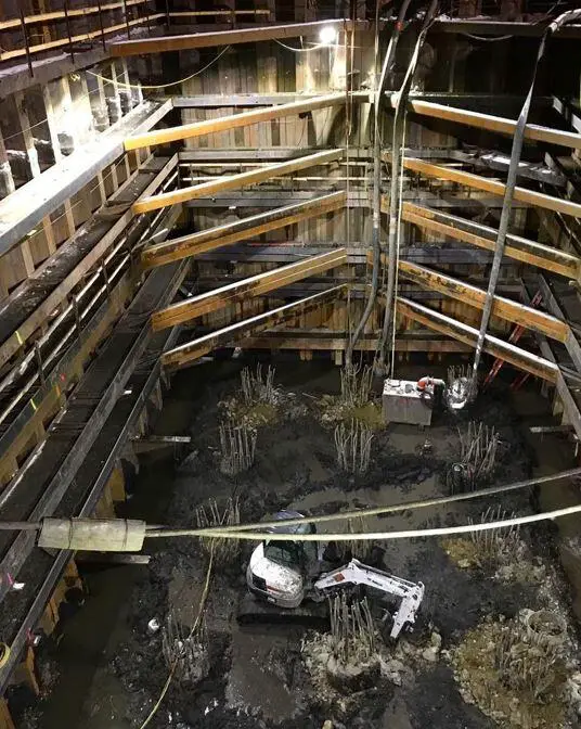
Steel sheet pile walls may be installed to form permanent cut-off, or used as temporary cut-off with piles removed at the end of construction. They offer the advantage of rapid installation and are relatively cheap. Additionally, they can support the sides of the excavation with suitable propping.
The disadvantages are that the seal may not be perfect, especially if obstructions are encountered. Vibration and noise of driving may be unacceptable on some sites, but ‘silent’ methods are available.
Vibrated beam wall
In this method, a grout injection nozzle is driven into a specially made wide flange beam section using a vibratory driver-extractor that is attached to the beam’s base. A self-hardening slurry is injected into the ground with the designed beam while it is vibrated into the ground to act as a lubricant.
When the beam is withdrawn, the extracted beam element leaves a minimum of a 4 to 6-inch panel that is filled with the self-hardening slurry. A continuous cutoff wall is created by the consecutive beam element insertions and the overlapping of the earlier beam insertions.
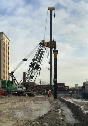
The Vibrating Beam construction technology enables operations in small spaces with little room for above-ground mixing or staging. This method also decreases soil disposal costs, which can be expensive when dealing with hazardous locations, as less excavation is needed. Permeabilities in the range of 10-8 cm/sec are capable of allowing for depths greater than 50 ft.
This method is applicable in open excavations in silts and sand but will not support the soil.
Slurry trench cut-off wall
A slurry cut-off wall or slurry trench wall is an excavation made deep into the ground while simultaneously pumping an engineered slurry mix into the trench. A permanent low permeability barrier to groundwater and leachates is created by the slurry cut-off wall after it is completed. Slurry trench cut-off walls also have the capacity to prevent the transportation/movement of a range of heavy metals and organic contaminants including volatile organic compounds (VOCs), hydrocarbons, diesel, solvents and tar.
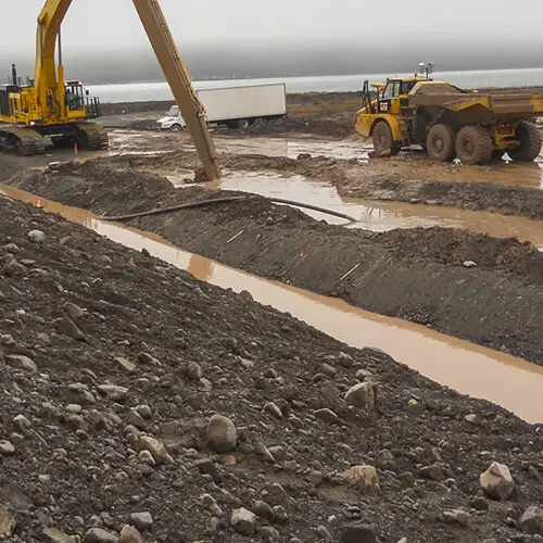
The slurry trench walls create a low permeability curtain wall surrounding the excavation and it is a permanent water exclusion system. Slurry trench walls are can be quickly installed and relatively cheap, but the cost increases rapidly with depth. It is very applicable in silts, sands, and gravel up to a permeability of about 5 x 10⁻³ m/sec.
Structural Concrete Diaphragm wall
Diaphragm walls can be used as cut-off walls for dams or excavation pits, as foundations, or as enclosures for structures. A diaphragm wall is a structural concrete wall constructed panel by panel in a deep trench excavation using either precast or in-situ concrete pours.
Diaphragm walls can serve as retaining walls, water-cut-off structures, deep foundations, basement walls, or as separating structures for underground facilities. They are constructed as ground-level concrete or concrete reinforced with steel walls. They are thought to be almost water-impermeable and deformation-resistant.

Diaphragm walls are permanent structures that support the sides of the excavation and often form the sidewalls of the finished construction. They can be keyed into rock and have the advantage of minimum noise and vibration. However, high cost may make the method uneconomical unless walls can be incorporated into a permanent structure.
It is applicable in side walls and shafts in most soils and weak rocks but the presence of boulders may cause problems.
Secant (interlocking)and contiguous bored piles
A retaining wall made of closely spaced bored piles can be used to construct a deep basement or a cut-and-cover tunnel. The piles could be constructed so that they almost touch each other (contiguous). A watertight retaining wall can be created by grouting the spaces between the piles.
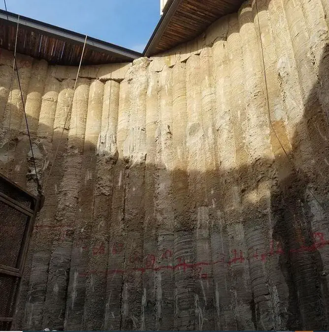
This method of construction results in a more effective form of structure when the piles interlock. The piles will typically need propping during soil excavation before the permanent floor and/or roof structure is finished.
Jet Grouting
In jet grouting, a stabilizing fluid is injected into the subsoil (or the soil being treated) under high pressure and high velocity. The high-velocity fluid jets are used to create different geometries of cemented soil in the ground and typically form a series of overlapping columns of soil/grout mixture that can prevent the movement of groundwater.
Jet grouting can be messy and create large volumes of slurry. There is a risk of ground heave if not carried out with care. Jet grouting is Relatively expensive and applicable for open excavations in most soils and very weak rocks.
Deep soil mixing columns
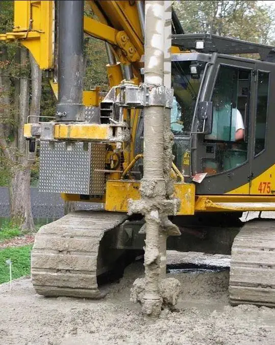
In this permanent water exclusion solution, overlapping columns are formed by in-situ mixing of soil and injected grout/cement using auger-based equipment. Soil mixing can be categorised into deep soil mixing and shallow soil missing. The mixture of binding agent and natural soil produces columns with very low permeability. This approach produces little spoil, and it is less flexible than jet grouting. It is relatively expensive.
Injection grouting using cementitious grout
Injection grouting is a process by which grouts are injected under pressure into open fissures, voids, cracks, and pores in a soil/rock mass. The grout fills the pore spaces, preventing the flow of water through the soil.
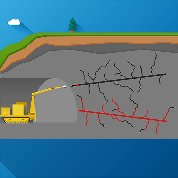
Equipment is simple and can be used in confined spaces. A comparatively thick zone needs to be treated to ensure a continuous barrier is formed. Multiple stages of treatment may be needed. The procedure is applicable to tunnels and shafts in gravels and coarse sands, and fissured rocks.
Artificial ground freezing
Ground freezing is a temporary water exclusion solution during construction. In this solution, a ‘wall’ of frozen ground (a freeze wall) is formed using brine or liquid nitrogen, which can support the side of the excavation as well as exclude groundwater.
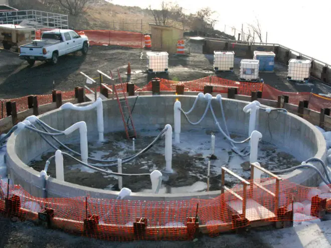
This approach may not work if groundwater flow velocities are excessive (> 2 m/day for brine or 20 m/day for liquid nitrogen). Liquid nitrogen is expensive but quick; brine is cheaper but slower. Liquid nitrogen is to be preferred if groundwater velocities are relatively high. Plant costs are relatively high.
Compressed air
In this temporary groundwater control solution, increased air pressure (up to 3.5 bar) raises pore water pressure in the soil around the chamber, reducing the hydraulic gradient and limiting groundwater inflow. Potential health hazards to workers. Air losses may be significant in high-permeability soils. High running and set-up costs.
It is suitable for confined chambers such as tunnels, sealed shafts and caissons.

