Gravity actions are normally used for the verification of portal frames for member resistances, lateral buckling, and torsional stability. Elastic design of portal frames is permitted by Eurocode 3, and the most significant load case (from experience) is the situation where the frame is subjected to gravity load from permanent actions and variable actions, taking into account the second-order effects and imperfection.
The load combination used for this is usually of the form shown in Equation (1);
p = 1.35gk + 1.5qk (1)
In the past, we have solved the problem of two hinged portal frames which are statically determinate due to the presence of internal hinge at the apex. However, it is not a very practical scenario as portal frames are required to be rigidly connected in order to achieve in-plane stability.
In this article, we are going to show how you can obtain the effects of actions (bending moment, shear force, and axial force) for a rigid portal frame subjected to an ultimate limit state load of 12 kN/m as shown in Figure 1. We will assume that the same universal beam section will be used for the column and the rafters (EI = Constant).
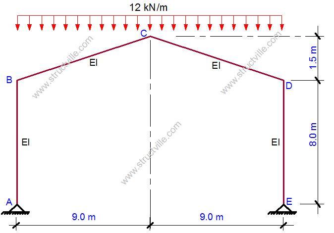
A little consideration will show that the frame shown in Figure 1 is statically indeterminate to the first order. Therefore, using the force method of analysis, we will need to reduce the structure to a basic system.
This is a process by which we remove the redundants (excess reactive forces) in the structure, to make it statically determinate. The basic system adopted must also be stable. This is shown in Figure 2.
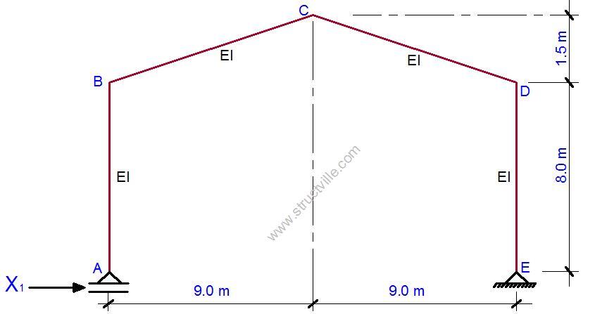
To proceed, we will now assign a unit force to the removed redundant horizontal reaction, and plot the bending moment diagram due to the unit force on the basic system as shown in Figure 3.
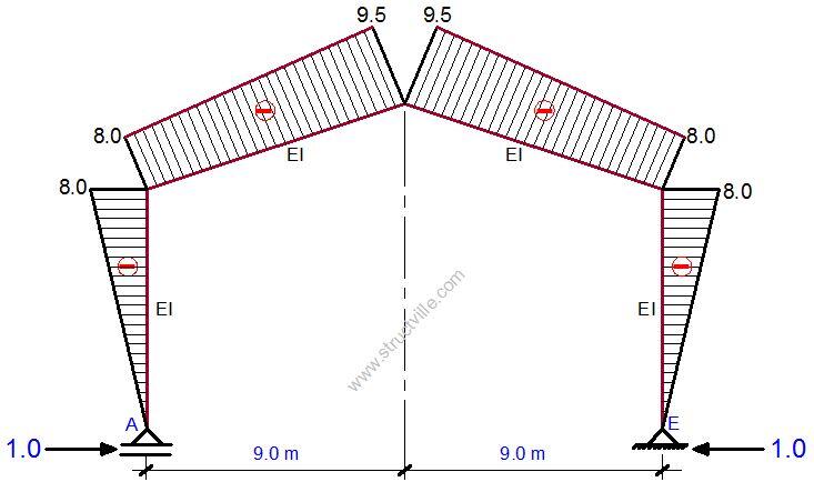
Since there is no other redundant support, we can apply the external load on the basic system. Due to the symmetry of the structure and the loading, we can verify that the vertical support reactions at A and E are given as shown in Figure 4;
Ay = Ey = (12 x 18)/2 = 108 kN
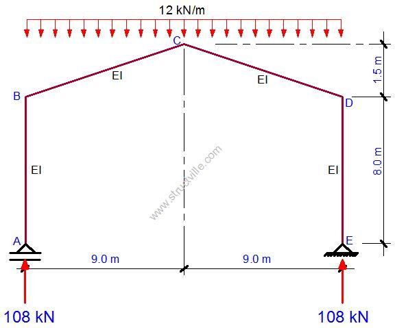
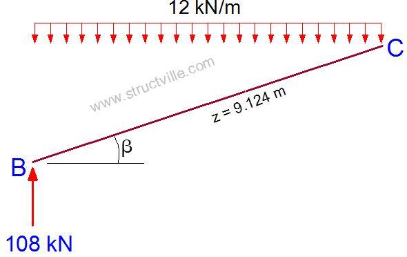
On observing Figure 4, we can see that there will be no bending moment in sections A-B and D-E, rather they will be subjected to compressive axial force of 108 kN. For member B-C, the bending moment will induced due to the reactive force and the externally applied uniformly distributed load. The free-body diagram of member B-C is shown in Figure 5.
We can verify that the geometrical properties of B-C are as follows;
The angle of inclination β = tan-1(1.5/9) = 9.462º
The length of the member z = √(1.52 + 92) = 9.124 m
The equation for the bending moment of the section can be given by;
Mz = [108 x cos(β) x z] – [12 x cos(β) x z2]/2
Mz = 106.53z – 5.918z2
At z = 9.124 m
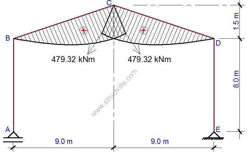
MCL = 106.53(9.124) – 5.918(9.124)2 = 479.32 kNm
The same thing is also happening at section C-D, and the bending moment diagram of the structure is shown in Figure 6.
The canonical equation for the structure is given by Equation (2);
δ11X1 + Δ1P = 0 ——– (2)
Where;
δ11 = Deflection at point 1 due to unit force at point 1
X1 = The actual external reaction at point 1 in the direction of the deflection due to externally applied load
Δ1P = Deflection at point 1 due to externally applied load
We are going to evaluate δ11 and Δ1P according to Vereshchagin’s rule which involves combining of the bending moment diagrams. For another example of how to apply Vereshchagin’s rule, click here.
Evaluation of δ11
In this case, the bending moment diagram of the unit force will combine with itself.
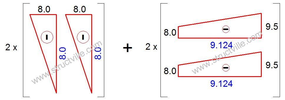
δ11 = 2 x [1/3 x 8 x 8 x 8] + 2 x 1/3 x [(8 x 8) + (9.5 x 8) + (9.5 x 9.5)] x 9.124 = 1741.867/EI
Evaluation of Δ1P
Here, the bending moment diagram due to the unit force will combine with the bending moment diagram due to the externally applied load as shown in Figure 8.
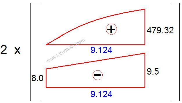
Δ1P = 2 x (1/12) x 479.32 x [(5 x 9.5) + (3 x 8)] x 9.124 = 52115.345
Substituting back into the canonical equation;
X1 = 52115.345/1741.867 = 29.919 kN (This obviously represents the horizontal reactions Ax and Ex)
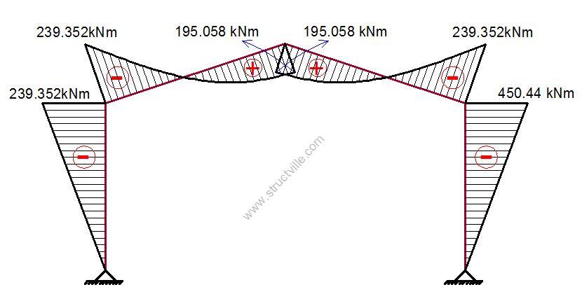
The final bending moment diagram can be obtained therefore as follows;
Mdef = M1X1 + M0
MA = ME = 0
MB = MD = (29.919 x -8) + 0 = -239.352 kNm
MC = (29.919 x -9.5) + 479.32 = 195.089 kNm
The bending moment diagram is shown in Figure 9, and the shear and axial forces can also be obtained accordingly.
Thank you for visiting Structville today… Please check back for more updates.



Good afternoon sir! This article was helpful.. I’m an undergraduate, currently writing a project on effect of seismic load on portal frames, multistorey building and telecommunication mast. Sir don’t know if you can put out material or give references that can help.