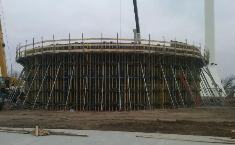
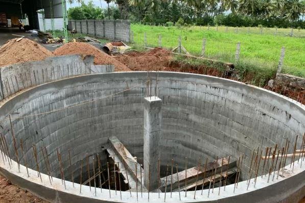
Water tanks are containment structures that are used for the storage of water for household, industrial, or commercial usage. Water tanks can be constructed in a variety of shapes such as circular (cylindrical), rectangular, oval, octagonal, etc. Furthermore, different materials such as reinforced concrete, steel, high-density plastics, reinforced polymers, etc have been successfully used in the construction of water tanks. The material to be used in the construction of water tanks must be durable, watertight, non-toxic, and strong enough to resist the hydrostatic pressure exerted by the stored water.
Circular water tanks have been shown by numerous studies to be more economical in terms of materials than square or rectangular tanks of comparable volume. However, there are more significant challenges and technicalities during the construction of circular tanks than rectangular tanks.
Water tanks can be elevated above ground level, placed on the ground surface, or buried under the ground. The design of underground circular water tanks involves the determination of the volume that will satisfy water demand requirements, and the selection of the section and reinforcements that will satisfy structural serviceability and ultimate limit state requirements.
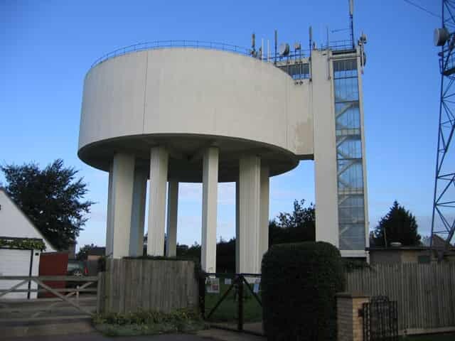
Circular water tanks that are buried under the ground can be subjected to a variety of forces such as;
- hydrostatic lateral pressure from the stored water
- gravity vertical load due to the stored water
- lateral earth pressure from the retained earth
- gravity forces from the self-weight of the tank and the cover
- surcharge forces around the tank
- earthquake load
- hydrostatic uplift
- Temperature effects, and
- other indeterminate forces and indirect actions
In order to adequately design underground circular water tanks, the effects of actions on the tank should be evaluated when the tank is empty, and when it is filled. The most critical service case should then be used in the structural design. For instance, when the tank is filled, the walls of the tank will be subjected to hydrostatic pressure from the stored water and lateral earth pressure from the retained earth. To a large extent, these pressures may neutralise each other due to their reverse directions and relatively close values, but it is often common to ignore earth pressure when assessing water tanks for ‘filled’ service conditions.
This makes sense because, during the testing or inspection of water tanks for leakage or sometime after the construction, it may be possible that the backfill earth may not be in place or removed. However, when the tank is empty, the walls will likely be subjected to earth pressure only. Therefore, it is logical to reinforce underground water retaining structures in the near face and the far face, just in case the loads are reversed.
Another important aspect in the design of reinforced concrete circular water tanks is ensuring that the section of the tank remains water-tight. This can be achieved using several methods but it is important that the crackwidth of the section remains less than 0.2 mm. Cracking is normal in reinforced concrete structures and can be caused due to direct tension or flexural stresses on the section. Early age cracking due to temperature and shrinkage of concrete can also be a problem.
The reinforcements provided, the thickness of the section, concrete cover, type of cement, type of formwork, and the temperature during casting are the main design factors that can influence the crack width of water retaining structures.
Stresses in Circular Water Tanks
Circular water tanks are designed to resist ring tensions due to the horizontal pressures of the contained liquid. The nature and distribution of internal stresses in circular water tanks depend mainly on the support conditions. According to Reynolds et al (2008), if the wall is free at the top and free-to-slide at the bottom then, when the tank is full, no vertical bending or radial shear exists in the walls of the tank. The ring tension at depth z is given by;
n = γzr
where γ is the unit weight of liquid, and r is the internal radius of the tank.
However, if the walls of the tank are connected to the base of the tank (say fixed) in such a way that no radial movement occurs, then the ring tension will be zero at the bottom of the wall. This affects the ring tensions throughout the lower part of the wall, and significant vertical bending and radial shear occur. Charts are available for the evaluation of these stresses under different types of loading and boundary conditions (see Reynolds et al, 2008; Table 2.75 – 2.77). The results gotten from the charts and finite element analysis using Staad Pro have been compared. To achieve a fixed support condition, the base of the tank will have to be expanded until the pressure distribution becomes uniform.
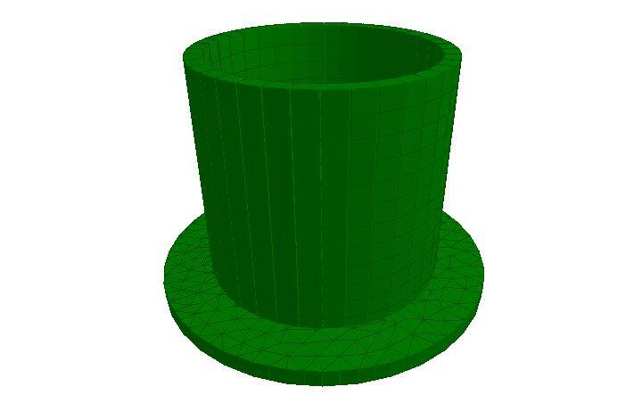
Alternatively, the base of the tank can be modelled as a plate on an elastic foundation. This can easily be achieved on Staad Pro software using the ‘plate mat’ or ‘elastic mat’ option as foundation/support. In this case, the property of the soil is represented using the modulus of subgrade reaction only.
According to Reynolds et al (2008), when slabs are supported on an elastic foundation, the influence on the behaviour of the tank will depend on the r/rk ratio. Where r is the radius of the base of the circular water tank and rk is the radius of the relative stiffness. The concept of the radius of relative stiffness rk was developed by Westergaard and is given by the Equation below;
rk = [Ech3/12(1 – v2)ks]0.25
where Ec, is the short-term modulus of elasticity of the concrete, h is the slab thickness, ks is the modulus of subgrade reaction, and v is the Poisson’s ratio.
Worked Example(s)
A circular water tank 3.8 m deep with a mean radius of 2 m is open at the top and fixed at the bottom. Determine, due to internal hydrostatic loading and lateral earth pressure, the maximum service values for circumferential tension, vertical moment, and radial shear in the walls of the tank. The walls of the tank are 300 mm thick, and the water level is taken to the top of the wall.
Solution
From Table 2.75 of Reynolds et al (2008);
lz2/2rh = 3.82/(2 × 2 × 0.3) = 12.03
At z/lz = 0.7; αn1 = 0.633
αm1 = 0.0026 and -0.0104
αv1 = 0.145
Hoop tension n = αn1γlzr = 0.633 × 10 × 3.8 × 2 = 48.108 kN/m
Vertical moment (span) m = αm1γlz3 = 0.0026 × 10 × 3.83 = 1.427 kNm/m
Vertical moment (edge/support) m = αm1γlz3 = -0.0104 × 10 × 3.83 = -5.706 kNm/m
Radial shear v = αv1γlz2 = 0.145 × 10 × 3.82 = 20.983 kN/m
Load Case 2
In the same way, if we assume that the tank is buried under the ground and backfilled with sand of angle of shearing resistance 30° and unit weight of 19 kN/m2. Then the coefficient of earth pressure at rest using Rankine’s theory is given by;
Ko = (1 – sin 30°)= 0.5
The maximum lateral earth pressure at the base of the wall will be given by;
p = koγz = 0.5 × 19 × 3.8 = 36.1 kN/m2
However, for the purpose of the formula to be used in the analysis, the unit weight of the material to be plugged into the equation can be represented as koγ = 9.5 kN/m3
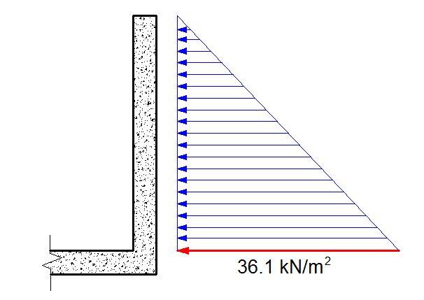
In the same vein, we calculate;
Hoop compression n = αn1γlzr = 0.633 × 9.5 × 3.8 × 2 = 45.7 kN/m
Vertical moment (span) m = αm1γlz3 = 0.0026 × 9.5 × 3.83 = 1.355 kNm/m
Vertical moment (edge/support) m = αm1γlz3 = -0.0104 × 9.5 × 3.83 = -5.421 kNm/m
Radial shear v = αv1γlz2 = 0.145 × 9.5 × 3.82 = 19.891 kN/m
In the design of the walls of the tank, the hoop tension must be resisted entirely by the ring reinforcements. When considering the hoop compression from the retained earth, the contribution of the concrete and steel can be considered (just like in the design of columns). It is typical to design the section for hoop tension and check for its adequacy in hoop compression.
The vertical reinforcements in each face of the wall must be able to resist the vertical moments due to the water pressure and the retained earth. This applies also to the span bending moments. Typically, the vertical reinforcements can be reduced accordingly as the wall goes higher. The quantity of reinforcement to be provided is also heavily influenced by cracking requirements.
In summary, the design of circular tanks is an interesting endeavour that can be carried out using hand calculations or computer software. Feel free to contribute to knowledge here.
