Any engineering or building structure must always require some site investigation. A complete analysis of the soil and groundwater conditions to a significant depth below the surface using boreholes and in-situ and laboratory tests on the materials encountered may be required, as well as a simple inspection of the surface soils with or without a few shallow trial pits.
The objectives of a geotechnical site investigation are to ascertain the conditions and properties of the soil, rock, and groundwater in the site, and to obtain extra pertinent information about the site.
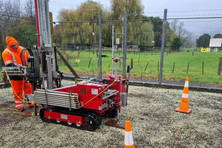
The type, size, and significance of the planned structure should be taken into account in the subsurface exploration program for a specific site. The number and depth of the necessary soil borings are determined by these criteria, which aid in the design of the site investigation program. Locating subterranean utilities should be part of the planning for a site investigation (i.e., phone, power, gas, etc.). As a result, many days before the planned site investigation, a local “call before you dig” service should be informed where available.
The significance and foundation configuration of the structure, the complexity of the soil conditions, and any knowledge that may be available regarding the behaviour of existing foundations on comparable soils all influence the scope of the investigation.
Categories of Site Investigation
Structures and earthworks are divided into three “geotechnical categories” according to Eurocode 7 (Geotechnical Design).
Geotechnical category 1 refers to light structures like single- or two-story buildings, low retaining walls, and buildings with column loads up to 250 kN or walls loaded to 100 kN/m. The qualitative investigations in this category can be restricted to verifying the design assumptions, at the latest, during the supervision of construction of the works, provided that the ground conditions and design requirements are known from prior experience and the ground is not significantly sloping. Visual inspection of the site, occasionally combined with inspection of small test pits, or sampling from auger borings are considered to be the main components of verification.
Conventional building types are included in category 2 structures on locations without anomalous dangers, unusually challenging ground conditions, or extraordinarily demanding loading conditions. This category includes conventional substructures such as retaining walls, bridge piers and abutments, excavations and excavation supports, rafts, piles, and shallow spread footings. Quantitative geotechnical data is needed, however standard testing techniques in the field and lab, as well as for analysis and design, are judged sufficient.
Structures in category 3 are those that are extremely massive, peculiar in nature, involve anomalous dangers, or have an unusually difficult ground or loading conditions. This category includes buildings that are located in seismically active regions.
The investigations essential for category 3 include any extra specialist research that may be required in addition to those thought to be sufficient for category 2. The processes and interpretations should be documented with references to the tests if specialized or unusual test procedures are necessary.
Site Investigations and Professional Practices
Buildings and engineering structures built upon deep excavations require extensive investigations. They offer vital information on the soil and groundwater conditions to contractors submitting bids for the work, in addition to information for foundation design. So, by collecting accurate and competitive bids based on an adequate understanding of the actual situation, money is saved.
If the cost of excavation work represents a sizeable portion of the overall project, a reputable contractor will not take a chance on it; instead, a comparably high sum will be added to the tender to account for the unforeseeable conditions. It follows the saying that “You pay for the borings whether you have them or not“.
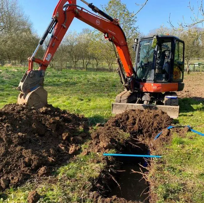
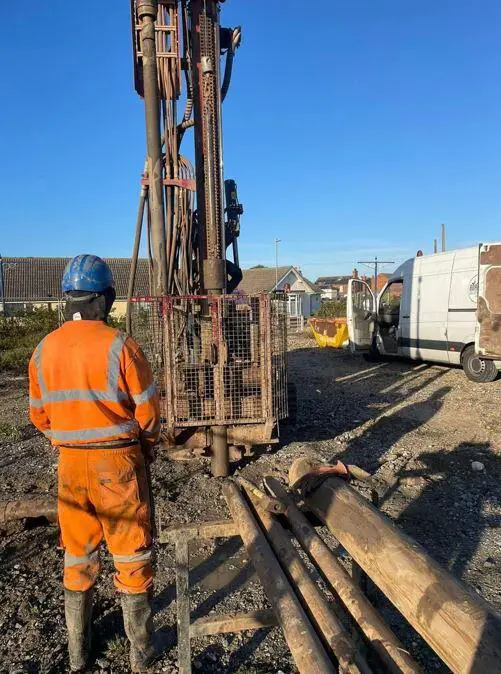
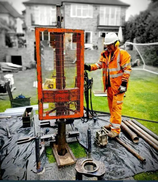
An engineer doing a site investigation may hire local workers for hand auger boring or trial pit excavation, or they may hire a contractor for boring and soil samples. The boring contractor may send samples to his own lab or to a third-party testing facility if laboratory analysis is necessary.
After that, the geotechnical engineer analyzes the soil mechanics for foundation design. Alternatively, the entire investigation could be handled by a specialized company with comprehensive capabilities for drilling, sampling, field and laboratory testing, and soil mechanics analysis.
If preferred, in-situ testing can take the place of laboratory testing. In any case, the engineer in charge of overseeing the field and laboratory work on a daily basis should keep the site investigation’s objective in mind and continuously evaluate the data in a manner similar to that used when writing the report.
The relevance of characteristics like weak soil layers, deep rock weathering, and sub-artesian water pressure can be explored in as much detail as may be necessary while the fieldwork is still on by avoiding the omission of important information in this way.
Whatever method the engineer chooses to conduct his site investigation, it is important that the people or groups doing the task are diligent and absolutely trustworthy. The engineer has a significant obligation to his employers to select a qualified organization and to satisfy himself through the field, lab, and office work inspections that the work has been completed accurately and thoroughly.
Information Required from a Site Investigation
For geotechnical categories 2 and 3 the following information should be obtained in the course of a site investigation for foundation engineering purposes;
- The general topography of the site, including surface configuration, adjacent property, the presence of watercourses, ponds, hedges, trees, rock outcrops, etc., and the accessibility for construction equipment and vehicles.
- The position of underground utilities such as sewers, water mains, cable television, and telephone lines.
- The overall geology of the region, with a focus on the primary geological formations that underlie the site and the potential for subsidence due to mining or other factors.
- The prior usage and history of the site, including any defects or failures of current or former buildings related to foundation issues and the potential for toxic waste contamination of the site.
- Any unique characteristics, such as the potential for earthquakes or environmental factors like flooding, seasonal swelling and shrinking, permafrost, or soil erosion.
- The accessibility and quality of locally produced building materials, including water for construction, building and road stone, and concrete aggregates.
- Information on normal spring and neap tide ranges, extreme high and low tidal ranges and river levels, seasonal river levels and discharges, tidal and river current velocities, wave action, and other hydrographic and meteorological data for marine or river structures.
- A thorough record of the soil and rock strata, groundwater conditions, and any deeper strata that may have an impact on the site’s circumstances in any way within the zones affected by foundation-bearing pressures and construction activities.
- The results of tests conducted in the field and laboratories on soil and rock samples relevant to the specific foundation design or construction issues.
- The results of chemical investigations performed on soil, fill materials, and groundwater to identify potential negative effects on foundation structures.
- The findings of chemical and bacterial investigations performed on contaminated soils, fill materials, and gas emissions to assess the potential health hazards.
Items (1) through (7) above can be obtained by a general site reconnaissance (the “walk-over” survey”) as well as through research of geological memoirs, maps, and other published records. Walking around the site area closely will often provide major clues about subsurface structures.
For instance, hidden swallow holes (sinkholes) in chalk or limestone formations are frequently revealed by sporadic depressions and noticeable irregularity in the ground surface; soil creep is shown by wrinkling of the surface on a hillside slope or leaning trees; abandoned mine workings are shown by old shafts or heaps of mineral waste; glacial deposits may be indicated by mounds or hummocks (drumlins) in a generally flat topography; and river or lake deposits by flat low-lying areas in valleys.
The existence of springs or wells and marshy terrain covered with reeds are surface indicators of groundwater (indicating the presence of a high water table with poor drainage and the possibility of peat). In the case of huge projects across wide areas, geological expertise should be sought.
Information on potential long-term changes in groundwater levels should be sought after. Pumping from deep mine shafts or ceasing groundwater extraction for industrial purposes can slowly raise groundwater levels over a large area.
Aerial photography is a useful tool for site inspections on large sites. Photographs may be taken from balloons, drones, or model aeroplanes. A great deal about a site’s topography and geomorphology can be learned through expert interpretation of aerial photos. A well-established science, geological mapping from aerial images is done by specialized companies.
Both outdated publications and old maps should be investigated because they may reveal the location’s prior uses and are especially helpful when looking into historically significant locations. Maps, memoirs, and images or photographs of a location in the past are frequently available at local libraries or museums. For information on buried services and coal mine workings in Britain, contact the Geological Survey and local authorities.
The list’s items (8), (9) (10), and (11) are obtained by boreholes or other subsurface research techniques, as well as through field and laboratory testing of soils or rocks. It is important to characterize soil types and consistency in accordance with accepted standards of practice. The British Standard Code of Practice Site Investigations, BS 5930, outlines the common descriptions and classifications of soils in Britain.
Subsurface Investigation Methods
Methods of determining the stratification and engineering characteristics of subsurface soils are as follows;
- Trial pits
- Hand auger borings
- Mechanical auger borings
- Light cable percussion borings
- Rotary open-hole drilling
- Wash borings
- Wash probings
- Dynamic cone penetration tests
- Static cone penetration tests
- Vane shear tests
- Pressuremeter tests
- Dilatometer tests
- Plate bearing tests
Detailed descriptions of the above methods as used in British practice are given in BS 5930 Site Investigations. Brief comments on the applicability of these methods to different soil and site conditions are given in the sections below.
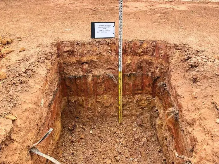
In most cases, geotechnical category 1 investigations use trial pits. For shallow foundations, they are helpful for assessing the quality of weathered rocks. The most reliable method for determining the stage of deposition and characteristics of filled ground is to use trial pits expanded to trenches.
In soils that remain stable in an unlined hole, hand and mechanical auger borings are also suitable for category 1 examinations. Augering, when done properly, gives the least disturbance to the soil out of any other boring technique.
In British practice, light cable percussion borings are typically utilized. The straightforward and durable machinery is ideally suited to the vastly different soil types in Britain, including the extremely stiff or dense stone glacial soils and weathered boulders with a consistency similar to soil. For specialized testing, large-diameter undisturbed samples (up to 250 mm) can be recovered.
Typically, the United States, the Middle East, and countries in eastern Asia use rotary open-hole drilling. The rotary drills are typically skid- or tractor-mounted and can drill through rock as well as through dirt. Sample sizes are typically limited to 50 mm in diameter, and hole diameters are typically lower than percussion-drilled holes. Although drilling fluids such as bentonite slurry or water are employed, specialized foams have been created to aid in collecting nice, undisturbed samples.
Wash borings are holes with a small diameter (about 65 mm) that are bored using a water flush and chiselling. Sampling is done using 50 mm internal diameter open-drive tubes or 50–75 mm standard penetration test equipment.
Investigations into over-watered soils employ wash probings. They are used, for instance, in dredging investigations, to find rock heads or a strong layer overlain by loose or soft soils. They consist of a small-diameter pipe shot down. The soils cannot be positively identified, and sampling is frequently not feasible.
Soil Sampling
There are two main types of soil samples which can be recovered from boreholes or trial pits;
(a) Disturbed samples, as their name implies, are samples taken from the examples of the boring tools are auger parings, the contents of the split-spoon sampler in the standard penetration test, sludges from the shell or wash-water return, or hand samples dug from trial pits.
(b) Undisturbed samples, obtained by pushing or driving a thin-walled tube into the soil, represent as closely as is practicable the in-situ structure and water content of the soil.
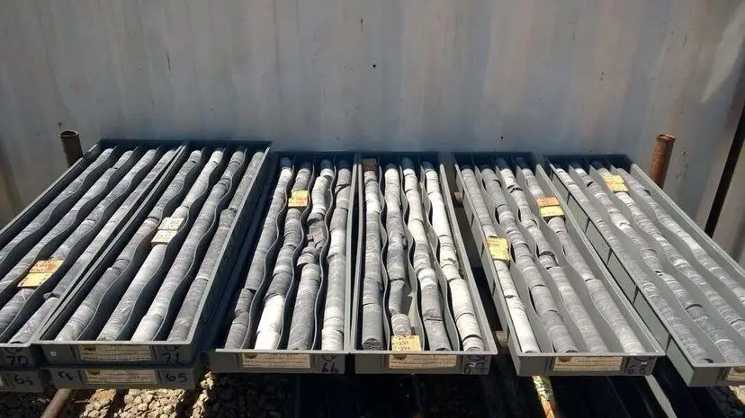
It is important not to overdrive the sampler as this compresses the contents. It should be recognized that no sample taken by driving a tube into the soil can be truly undisturbed. Disturbance and the consequent changes in soil properties can be minimized by careful attention to maintaining a water balance in the borehole. That is, the head of water in the borehole must be maintained, while sampling, at a level corresponding to the piezometric pressure of the pore water in the soil at the level of sampling.
This may involve extending the borehole casing above ground level or using bentonite slurry instead of water to balance high piezometric pressures. The care in the sampling procedure and the elaborateness of the equipment depends on the class of work which is being undertaken, and the importance of accurate results on the design of the works.




Good afternoon, I have read some of your publications on pile load test, please I wish to know the allowed settlement for a 900mm pile diameter.
Thanks
Kindly read through the article below
https://structville.com/failure-load-of-pile-foundation