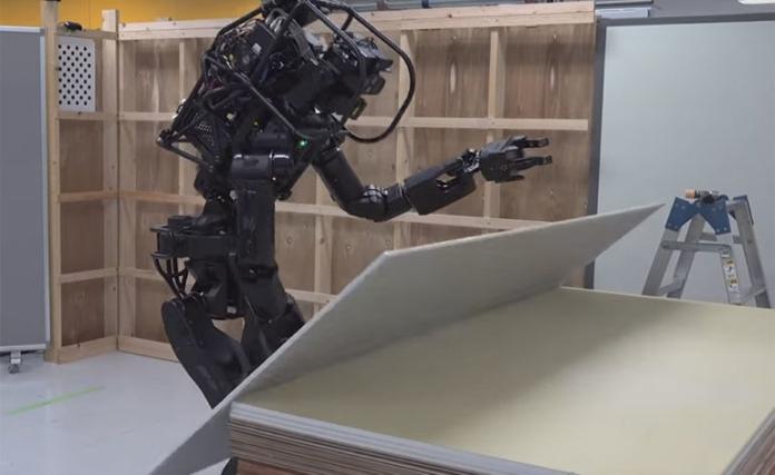
The construction industry remains one of the least automated industries which depend on manual human labour for maximum productivity. The role of robots in construction operations is still very insignificant when compared other industries. However, robotic automation stands as a promising field for construction, as it offers a safer and efficient approach for handling building resources on site which extends the limits for more creative and customizable architecture.
Due to the complex and highly dynamic nature of the construction industry, robots cannot blindly execute predefined instructions as obtainable in other more deterministic industries. This makes it difficult for robots to adapt to the ever changing construction sites. It has therefore been found important that robots be equipped with advanced vision capabilities to enable them observe, cope, and adapt to busy construction sites.
3d rendering robotic arms with building
Researchers from Barlett School of Architecture, UCL, London UK, investigated a flexible 3D object recognition approach to easily reference building components to a vision system and be able to deal with objects’ imprecision. This is due to the fact that dealing with unique, irregular structures require robust object estimation approaches to enable on-site autonomous robotic assembly applications. To achieve this, they used a virtual scanning process which takes the “ideal” representation model of all the objects found in the Building Information Modelling (BIM) model as the guide for finding all “best match objects” on site, without the need for physically scanning or labelling the objects to reference them. The study was published in Springer – Construction Robotics.
According to the authors,
Our overarching hypothesis is that using the available BIM data as the reference model will have the potential not only to locate highly matched known objects with a threshold to accommodate material deviations, but also flexibility to find the best match objects from an unknown pile… Our goal was to detect and manipulate the best-matched known objects in an unsorted pile on site according to a given design in the form of the BIM model. Therefore, we developed a holistic approach that includes our detection method, and an automated process to grasp, manipulate, and determine the assembly sequence based on the design scheme of the structure and awareness of the surrounding context.
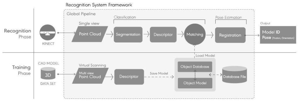
In their methodology, 3D object recognition was adopted using global feature based approach due to its flexibility to work with noisy data. 3D CAD representation of the objects coming from the BIM model was used for training instead of using physical scan models of the objects. After the recognition stage, object to robot calibration was done.
Recognition System Framework, which comprises two different phases: an online recognition phase and an offline virtual training stage [1]
The recognition system proposed in the study showed that the method of using the virtual representation coming from the BIM model instead of having to scan the actual model brings advantages regarding flexible setup and affordable recognition. The experiments also showed that the system able to detect and construct several structures with inherited imperfections within acceptable tolerances. However, it also showed several limitations related to the object’s geometrical characteristic and its implication on the successful detection of the whole process success.
Reference for the full research paper: [1] Mohamed Dawod and Sean Hanna (2019): BIM‑assisted object recognition for the on‑site autonomous robotic assembly of discrete structures. Construction Robotics (2019) 3:69–81 https://doi.org/10.1007/s41693-019-00021-9
Disclaimer: The findings of this research work has been shown on www.structville.com because it is an open access article which is distributed under the terms of the Creative Commons Attribution 4.0 International License (http://creativecommons.org/licenses/by/4.0/), which permits unrestricted use,distribution, and reproduction in any medium, provided you give appropriate credit to the original author(s) and the source, provide a link to the Creative Commons license, and indicate if changes were made.
Non-linear analysis can be used when all of the members, elements and support springs are linear except for cables and/or preloaded truss members. This analysis is based on applying the load in steps with equilibrium iterations to converge at each step. In Staad Pro software, the iteration continues at each step until the change in deformations is small before proceeding to the next step. If not converged, then the solution is stopped. The user can then select more steps or modify the structure and rerun.
This method assumes small displacement theory for all members/trusses/elements other than cables and preloaded trusses. The cables and preloaded trusses can have large displacement and moderate/large strain. Pretension is the force necessary to stretch the cable/truss from its unstressed length to enable it to fit between the two end joints. Alternatively, you may enter the unstressed length for cables.
The analysis sequence is as follows:
(1) Compute the unstressed length of the nonlinear members based on joint coordinates, pretension, and temperature.
(2) Member/Element/Cable stiffness is formed. Cable stiffness is from EA/L and the sag formula plus a geometric stiffness based on current tension.
(3) Assemble and solve the global matrix with the percentage of the total applied load used for this load step.
(4) Perform equilibrium iterations to adjust the change in directions of the forces in the nonlinear cables, so that the structure is in static equilibrium in the deformed position. If force changes are too large or convergence criteria not met within 15 iterations then stop the analysis.
(5) Go to step 2 and repeat with a greater percentage of the applied load. The nonlinear members will have an updated orientation with new tension and sag effects.
(6) After 100% of the applied load has converged then proceed to compute member forces, reactions, and static check.
Note that the static check is not exactly in balance due to the displacements of the applied static equivalent joint loads.
Non-linear Cable Analysis Parameters
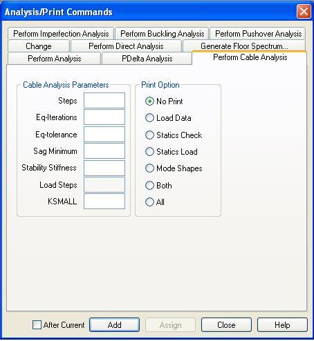
If you open the cable analysis command on Staad Pro, you will see cable analysis parameters which can be confusing at first sight. Staad Pro advanced training manual offers some insight on the definition of the parameters and the values to use.
Steps: The number of steps if entered should be in the range 5 to 145.
Eq-iterations: This is the maximum number of iterations permitted in each load step. The default value is 15 and should be in the range of 10 to 30.
Eq-tolerance: This is he convergence tolerance for the above iterations. Default value is 0.0005.
Sag minimum: Cables may sag when tension is low. This is accounted for by reducing the E value. Sag minimum may be between 1.0 (no sag E reduction) and 0.0 (full sag E reduction). Default is 1.0. If sag minimum is entered, it should be in the range 0.7 to 1.0 for a relatively simple process. As soon as SAGMIN becomes less than 0.95 the possibility exists that a converged solution will not be achieved without increasing the steps or the pretension loads. The Eq iterations may need to be 30 or more. The Eq tolerance may need to be greater or smaller.
Stability stiffness: A stiffness matrix value that is added to the global matrix at each translational direction for joints connected to cables and nonlinear trusses for the first Load Steps. The amount added linearly decreases with each of the Load Steps (Load Step is 1.0 if omitted). If stability stiffness is entered, use 0.0 to 2.0 but the default value is 0. For Load Steps use a maximum value of 145.
K small stiffness: This is a stiffness matrix value, that is added to the global matrix at each translational direction for joints connected to cables and nonlinear trusses for every load step. If entered, use values between 0.0 to 1.0 but the default value is 0.0. This parameter alters the stiffness of the structure.
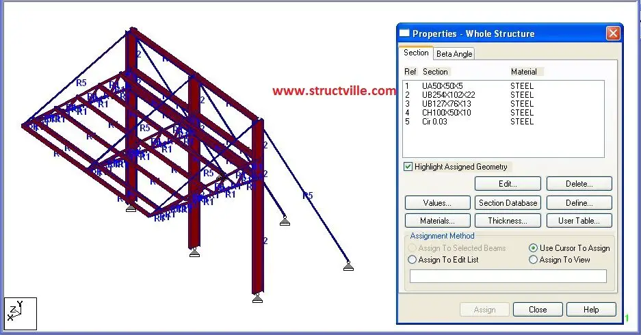
Analysis Example Let us analyse the cable stayed canopy loaded as shown below. The structure comprises of UB 254 x 102 x 22 stanchions supporting cantilevered trusses of UA 50 x 50 x 5 sections. Purlins on the trusses are made of channel sections CH 100 x 150 x 10. Cables are made of 30 mm diameter steel wires and UB 127 x 76 x 13 are used to brace the stanchions in the lateral directions. The loading applied on the structure is the self weight and UDL of 1.5 kN/m on the purlins.
In the analysis, an initial tension of 0.1 kN was applied in the cable members using the default parameters (leaving the cable analysis parameters blank). However, the load case refused to converge after iterations. The parameters that gave acceptable convergence are shown below.
Analysis Results
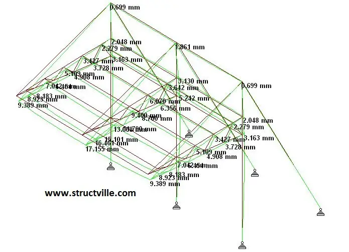
The displacement of the cable stayed canopy is shown below;
The maximum displacement in the truss was observed to be 17.155 mm.
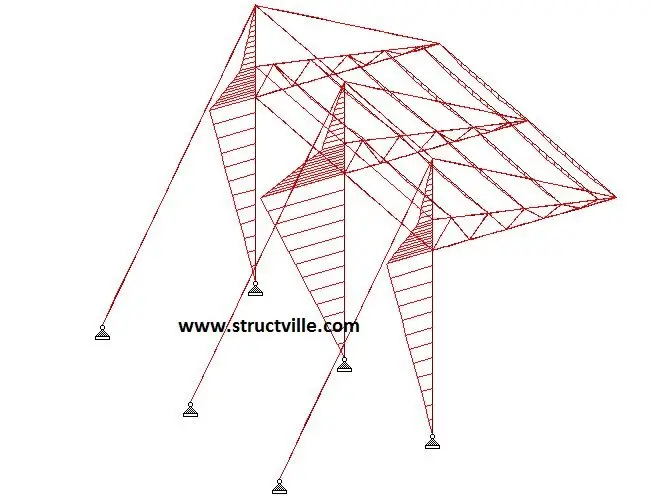
The bending moment in the intermediate column was observed to be 27.2 kNm. The shear force in the same column was observed to be 9.08 kN with an axial force of 45.5 kN.
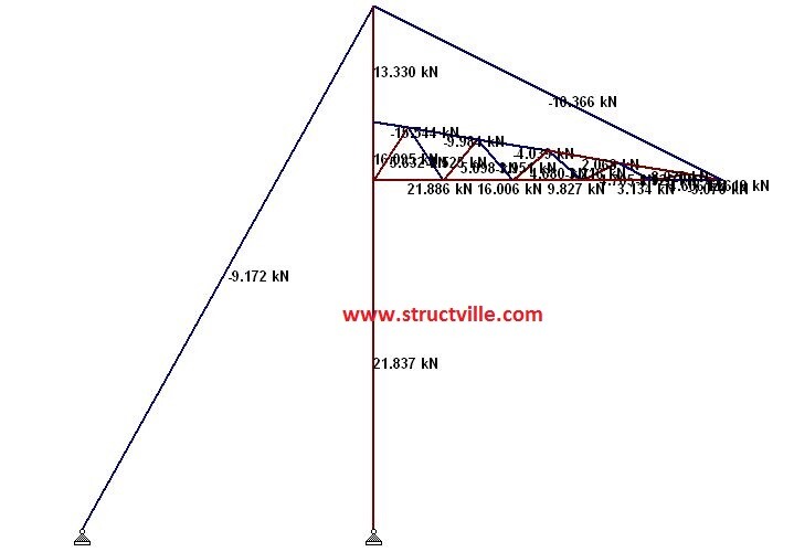
The axial forces in the cables and trusses of the intermediate members are shown below;
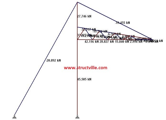
The axial forces in the cables and trusses of the end members are shown below;
Thank you for visiting Structville today. God bless you.
Building service systems (BSS) are important components that makes a building functional and habitable. BSS includes piping network of fresh water and wastewater, electrical installation network, air conditioning systems, fire prevention and protection systems, and communication systems. These are usually sumarised as MEP which stands for Mechanical, Electrical and Plumbing services design.
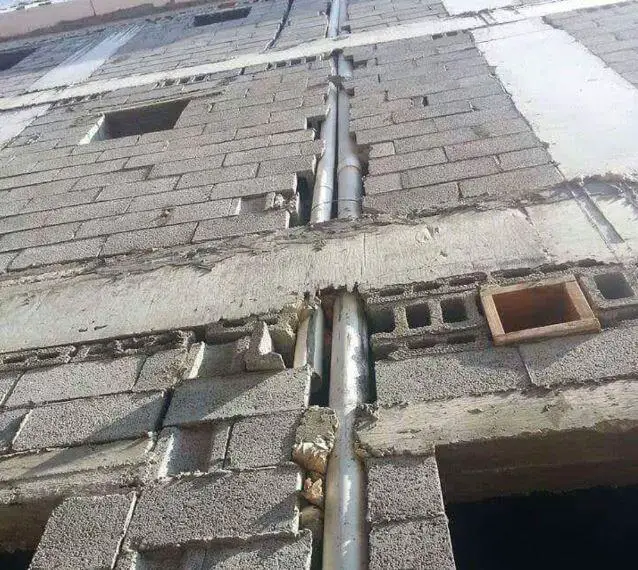
In the design process, BSS are improtant components which have great impacts on architectural and structural designs. It is generally accepted that integrating the service systems and their components into the architectural and structural designs, and coordinating between these systems help avoid major obstacles during the construction process. In some buildings in Nigeria, it is common to see incoherent arrangement of plumbing systems, chiselling/breaking down of structural members to accommodate mechanical systems and other construction setbacks due to uncoordinated MEP design at an early stage.
Unsightly and inefficient arrangement of plumbing system in a building
Usually, after completing the designs, the MEP coordination process begins by holding meetings between the representatives of the general contractor and specialty trades. The MEP systems coordination influences the productivity of all designers of multidisciplinary backgrounds involved in the design process. Any errors or mistakes during designing or constructing the project in the MEP systems would lead to time consuming tasks, budget waste, labour time increment, and project time extension.
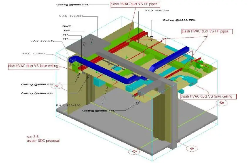
Service system, HVAC clashes with both fire system pipes and the suspended ceiling (Wael and Weldy, 2020)
In a research carried out by authors from Applied Science University, and University of Bahrain and published in Journal of Information Technology in Construction, the need to integrated BSS early into preliminary designs (architectural and structural) were reviewed and studied. According to the authors,
The integration BSS inside the building in the early phases of design will save cost and prevent time-consuming modifications. Due to the late integration of the building service systems BSS in the design, negative impact on both the exterior and the interior, may occur. Within the building industry, there has been increasing interest to the building service systems BSS integration, in order to enhance design outcomes, and to detect or even avoid the service systems’ clashes and conflicts.
Problems of 2D drawings
The coordination processes of overlaying two-dimensional drawings of different service systems, each of which is designed by different specialised designers has been identified by the authors as a major cause of clashes and conflicts. The accuracy of this process depends on the experiences of architects and structural engineers in order to avoid the possible conflicts and to include the systems’ components and spatial requirements into the design and its spaces.
Actually, errors may not be fully detected by these traditional processes till the construction stages. Identifying conflicts in the 2D-drawings of service systems is a challenging process, since it depends on designers’ experience. These possible errors or conflicts can negatively affect the projects in many aspects, particularly in the case of being undetected after the construction completion. This can consequentially impact the project’s spaces to accommodate the systems’ components and requirements.
3D to the rescue
Although 2D drawings are still extensively used in every aspect of a building project, there is a strong movement led by the architects to transform to 3D models.
Using 3D digital modelling in the processes of design and coordination not only improves the designers’ raw imagination by representing a 3D model including the components of the service systems, but also eliminates the errors generated from the lack of designers’ experiences by visually presenting all systems’ components. Employing digital modelling eases the processes of coordination and design, and makes them more accurate. Authorities, stakeholders and decision makers will gain many advantages, such as: creating a detailed model of both the design and the service systems which makes their decisions more reliable and accurate.
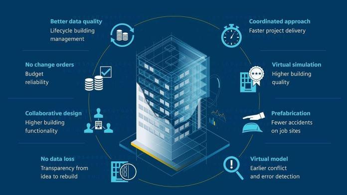
Building Information Modelling (BIM) is an approach and a process in which the design model potentially includes various building information of different components and spaces, in order for the users to visualise, manage, analyse and/or design in a better way. BIM approach offers an effective assistance represented in making a multidisciplinary model that has BSS in one detailed model, which helps discover and solve any obstacles of overlaps or/and conflicts. Unlike other digital tools that help the imagination capabilities of architects or architecture students, BIM proceeds beyond to unveil and expose possible problems that may appear in the later processes of designing and construction.
Conclusion
Citing previous research works, the authors concluded clash detection has been favoured over the clash avoidance due to cultural practices and lack of technologies to support clash avoidance. From empirical evidence of past research works, MEP-related clashes has been strongly linked to the cultural practices of isolated working among designers, and lack of specialised professional training among designers.
The paper based on the qualitative analysis of both the real projects of construction industry and the student projects of academia, concludes that integrating the MEP systems into the conceptual design phases eliminates the clashes and conflicts that may occur in later stages, and concurrently the possibility of not detecting these conflicts till the construction process.
Reference Wael Abdelhameed, Weldy Saputra (2020): Integration of building service systems in architectural design. Journal of Information Technology in Construction (ITcon), Vol. 25, pg. 109-122, DOI: 10.36680/j.itcon.2020.007
Disclaimer The findings of this research has been published on www.structville.com because it is an open access article distributed under the terms of the Creative Commons Attribution 4.0 International (https://creativecommons.org/licenses/by/4.0/), which permits unrestricted use, distribution, and reproduction in any medium, provided the original work is properly cited.
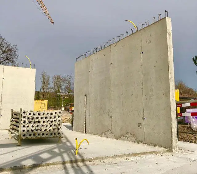
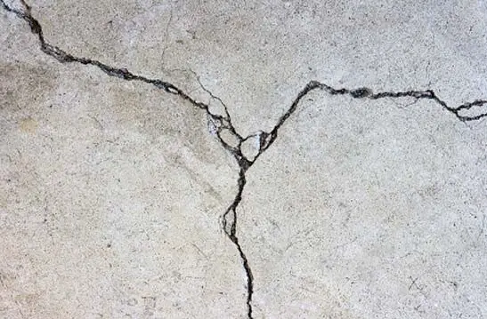
If movement (expansion and/or contraction) is restricted within a young concrete element, tensile stresses will develop which will lead to cracking. This restriction to movement is normally referred to as restraint. Restraints may be internal or external to the element. Internal restraint occurs due to differential temperature changes within a mass concrete element and can cause surface and/or internal cracking. However, it is only significant in very thick sections (1000 mm or more). Internal restraints are not considered in this article.
External restraints are due to the support/casting condition of the concrete. However, external restraints take two basic forms;
(1) End restraints (2) Edge restraints
End restraint
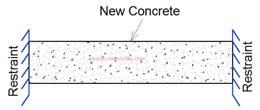
End restraints occurs when the edges of a young concrete are prevented from movement (see Figure below). This typically occurs in suspended slab cast between rigid cores, walls or columns, in infill bays, ground slab cast on piles, large area ground slabs restrained locally, e.g. by piles, columns or column foundations or by a build up of friction, walls cast against secant, contiguous concrete or steel sheet piled walls etc (CIRIA C660).
Schematic model of end restraint in concrete
Edge restraint
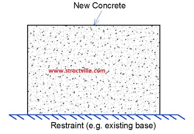
This typically occurs where the young concrete section (say a wall) is cast on a hardened concrete base (see Figure below). This means that restriction is only in one direction, and there is interaction between the old and new concrete in terms of distribution of cracks. Edge restraint is different from end restraint because the crack width is a function of restrained strain rather than the tensile capacity of the concrete.
Schematic model of edge restraint in concrete
In some cases also, there can be combination of end restraint and edge restraint.
Restraint Factors
The level of restraint in a young concrete imposed by adjoining element is commonly described using restraint factors. The degree of restraint, R, is generally defined as the ratio between the actual stress in a contracting body and the stress imposed under full restraint.
Degree of restraint R = Actual imposed stress / Imposed stress at full restraint
It is recognised that is difficult to determine the degree of restraint correctly, but it is important to obtain restraint factors that are as accurate as possible. According to CIRIA C660, the restraint factors given by BS 8110-2 and HA BD 28/87 reflects true restraint values, while the restraint factors from BS 8007 and EN 1992-3 has a modification factor of 0.5 to account for creep under sustained loading.
ACI (1990) (cited by CIRIA C660) developed method for estimating edge restraint based on the relative geometry and stiffness of the old and new concrete. The equation is given by;
Restraint at the joint Rj = 1/(1 + AnEn/AoEo)
Where;
An is Cross-sectional area of the new (restrained) pour Ao is the cross-sectional area of the old concrete En is the modulus of elasticity of the new pour concrete Eo is the modulus of elasticity of the old concrete
However, CIRIA C660 identified that the relative areas of influence of Ao and An may be difficult to define. Therefore the following simple rules were recommended;
For a wall cast at the edge of a slab (An/Ao) = (hn/ho) (thickness of new concrete/thickness of old concrete)
For wall cast remote from the edge of the slab (An/Ao) = (hn/2ho)
En/Eo ranges from 0.7 to 0.8 (but 0.8 is recommended)
Based on CIRIA C660, the values in Table 1 can be used for edge restraint based on An/Ao or An/2Ao ratio.
Table 1: Values of Edge Restraint Factors (According to CIRIA C660)
The values of restraint factors for different conditions as given by different codes is summarised in the Table 2.
Table 2: Values of Restraint Factors (BS 8110-2 and EN 1992-3)
Thank you very much for reading.
Get this publication below for a cheap price by clicking on the image. It goes a long way in supporting what we do here at Structville. To read about the publication, click HERE. Thank you for your kind consideration.
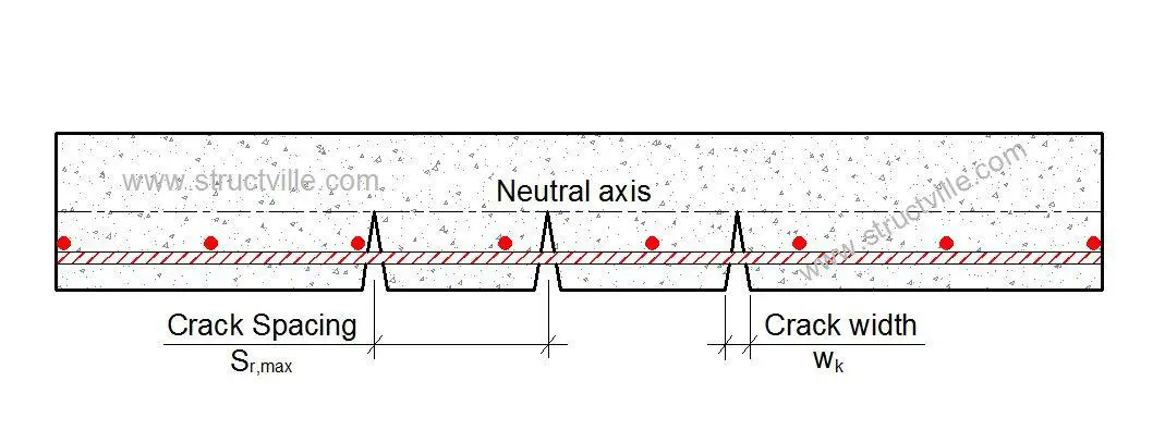
Eurocode recognises that cracking is normal in concrete subjected to bending, shear, torsion, and restraint from movement (clause 7.3.1 EN 1992 1-1). Cracking is assumed to occur when the restrained strain exceeds the tensile strain capacity of the concrete. This means that for cracking to occur, some part or the whole of the concrete section must be in tension. Crack width is predicted by multiplying crack inducing strain, (the strain dissipated by the occurrence of cracking) εcr, by crack spacing, sr,max.
Cracking occurs due to the low tensile strength of concrete, and we normally use reinforcements to assist is controlling cracking. What happens in this case is that the tensile stress in the concrete must be transferred to the steel if cracking must be controlled.
To achieve this, a minimum amount of reinforcement must be provided in order to have small cracks occurring at intervals instead of having one single large crack. However, provision of this minimum reinforcement is not sufficient for controlling crack widths. As a matter of fact, direct crack width calculation must be carried out if the water tightness of the tank must be guaranteed.
Get this publication below for a cheap price by clicking on the image. It goes a long way in supporting what we do here at Structville. To read about the publication, click HERE. Thank you for your kind consideration.
Cracking occurs in concrete when the restrained strain exceeds the tensile strain capacity of the concrete. In critical elements like water retaining structures, crack control is verified by carrying out direct calculation of the crack width. Crack width is calculated by multiplying the crack inducing strain and the crack spacing (i.e. the movement over a length equal to the crack spacing). This also involves limiting the bar size and/or spacing to recommended limits.
According to expression 7.8 of EN 1992-1-1, crack width wk in a concrete element is given by;
wk = sr,max εcr
where; sr,max = Maximum crack spacing
sr,max= 3.4c + 0.425 (k1k2ϕ/ρp,eff)
Where; c= nominal cover, cnom in mm in accordance with BS EN 1992-1
k1 = 0.8 for high-bond bars (Note that for early age cracking calculations CIRIA C660 suggests a value of 1.14 to account for poor bond conditions, see EN 1992-1-1 for poor bond conditions)
k2 = 1.0 for tension (e.g. from restraint) = 0.5 for bending = (ε1 + ε2)/2ε1 for combinations of bending and tension where ε1 is the greater tensile strain at one surface of the section under consideration and ε2 is the lesser tensile strain (i.e. = 0 if strain at second surface is compressive).
ϕ= diameter of the bar in mm.
ρp,eff= As/Ac,eff
This is calculated for each face.
Ac,eff= min[0.5h; 2.5(c + 0.5ϕ); (h – x)/3]
Where; h = thickness of section x= depth to neutral axis.
εcr= Crack-inducing strain in concrete
εcr = (εsm – εcm)
Crack-inducing strain is derived according to whether the element is subject to:
(2) end restraint (3) flexure and/or combinations of flexure and tension from load
Note: It is assumed that the reinforcement will be spaced at reasonably close centres. Where spacing exceeds 5(cnom + ϕ/2), BS EN 1992-1-1 Exp. (7.14) dictates that;
sr,max = 1.3 (h – x)
Thank you very much for reading.
Get this publication below for a cheap price by clicking on the image. It goes a long way in supporting what we do here at Structville. To read about the publication, click HERE. Thank you for your kind consideration.
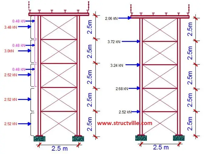
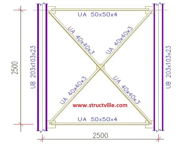
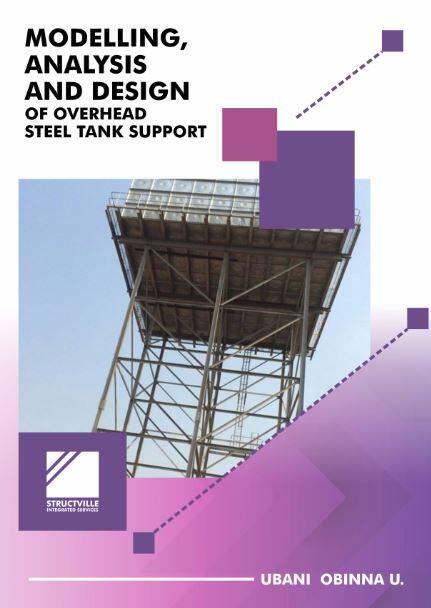
This book has been written to address an area of structural design which is usually neglected by clients, architects, and homeowners. During the brief for the structural design of a residential building or a villa, serious attention is not usually paid to the structural design of the overhead tank supports. Overhead tank supports are structural members which are subjected to heavy imposed loads and environmental actions. As a result, they should be treated with much seriousness as other structures.
This publication, therefore, aims to cover the basic requirement or knowledge needed to design steel tank supports. However, it cannot suffice for full structural engineering textbooks on the design of steel structures.
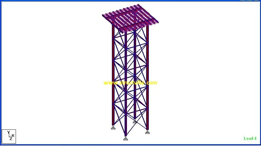
Staad Pro is a popular structural engineering software. It has been utilised in this book to demonstrate, model, analyse, and obtain the internal forces that are induced in a steel tank support. The subsequent structural design of the structure is carried out manually in accordance with Eurocode 3 (BS EN 1993-1-1:2005). The procedure presented in the book is also applicable to the design of steel members in other structures.
Chapter one of the book talks about the rationale behind the adoption of overhead tanks, the alternatives, and some engineering principles in water supply and distribution in residential buildings and large-scale municipal water supply.
Chapter two discusses the structural schemes that can be adopted for overhead steel water tank supports. The members of the frame and their functions are also described.
Chapter three talks about the application of wind action to open lattice steel frame structures according to BS EN 1991-1-4. A practical wind action analysis is also presented.
In chapters four and five, the modelling steps of overhead steel tanks in Staad Pro software, and the results of the analysis are presented.
Chapter six shows the actual structural design and verification of the structural members according to the requirements of Eurocode 3.
The special benefits of purchasing this textbook are;
(1) Full design manual on modelling, analysis, and design of overhead tanks (2) FREE video tutorial on modelling and analysis of overhead tanks on Staad Pro Software (3) FREE AUTOCAD file on detailing of steel tank support members (4) Knowledge on application of wind load on open lattice structures (5) Design of structural members subjected to various loading
Get these delivered to your e-mail immediately for NGN 2,550 only by clicking HERE.
What comes to your mind when you hear the word engineering? Does it bring to your imagination skyscrapers, bridges, highways, tech devices as well as every smart and intelligent innovation that are making our lives better? We are in a time where the conventional engineering education will no longer be to teach the engineering students all they need to learn. Modern Engineering education should be geared towards giving students patterns, ideas, and techniques that they need to continue to educate themselves for the future.
Technological advancement has stirred the world to move at a rapid rate and every career field must prepare differently than they have in the past. Engineers of the future must possess skills like innovation, entrepreneurial vision, and teamwork. As history commonly repeats itself, engineers are now shifting into more leadership roles within corporations, similar to engineers’ migration into business in the industrial age.
In the industrial age, engineers like Henry Ford and Nikola Tesla were known for their skills in engineering and business. Now we are approaching our “fourth industrial revolution” as coined by Prof. Klaus Schwab, founder and executive chairman of the World Economic Forum.
The fourth industrial revolution according to Prof. Schwab is characterized by a range of new technologies that are fusing the physical, digital and biological worlds impacting all disciplines, economies, and industries and even challenging ideas about what it means to be human.
However, as much as there are various engineering career majors, there are various techniques to boost learning, career development, and assimilating knowledge. To some engineers, the major focus is on networking, training, and development.
Three (3) major career development considerationsare;
Learning Style: Learning style ranges from visual learning by seeing and practicing, auditory learning by hearing and listening, and kinesthetic which is learning by touching and practicing.
Type of Gap: Its no surprise engineers strive to get better by filling some various gaps which includes, knowledge gap, skills or experience gap and leadership gap. These gaps are closed by education and training, exposure to situations so as to learn.
Leadership gaps: Learning and performing at high levels mostly from senior management positions in organizations.
As the world becomes increasingly interconnected, there is a need for shorter product developments. Sustained technological advancement suggests that engineers would lead projects and engineering professions would take on extra responsibilities. This is an exciting time to be alive and to be an everyday engineer. Check out available civil engineering jobs.
Be passionate for more. Stay curious, stay inspired.
Civil Engineering is the oldest engineering profession in the world, and has been at the forefront of developing infrastructures such as buildings, roads, bridges, towers, sanitary and water supply systems, etc for the benefit of mankind. Different professional bodies have been formed in different countries to foster competence, development, unity, and coherence in the civil engineering profession. This article highlights the biggest civil engineering professional bodies in the world whose members are widely recognised as professionals.
The American Society of Civil Engineers was founded in the year 1852, and represents more than 150,000 members of the civil engineering profession in 177 countries. It is the oldest engineering society in the United States of America. ASCE stands at the forefront of a profession that plans, designs, constructs, and operates society’s economic and social engine – the built environment – while protecting and restoring the natural environment.
Through the expertise of its active membership, ASCE is a leading provider of technical and professional conferences and continuing education, the world’s largest publisher of civil engineering content, and an authoritative source for codes and standards that protect the public. ASCE publishes about 35 technical journals to build professional knowledge.
The Society advances civil engineering technical specialties through nine dynamic Institutes and leads with its many professional- and public-focused programs. Members have special benefits of free PDHS, mentorship, discounts on journal and articles, free and paid webinars and conferences with discounts, career enhancements, etc.
The Institution of Civil Engineers UK was formed in the year 1818 and boasts of about 95,000 civil engineer members in more than 150 countries. ICE can be regarded as the oldest civil engineering professional body in the world. The Institution aims to support the civil engineering profession by offering professional qualification, promoting education, maintaining professional ethics, and liaising with industry, academia and government. Under its commercial arm, it delivers training, recruitment, publishing and contract services.
ICE is a licensed body of the Engineering Council and can award the Chartered Engineer (CEng), Incorporated Engineer (IEng) and Engineering Technician (EngTech) professional qualifications. ICE publishes hundreds of civil engineering journals.
The International Association for Bridge and Structural Engineering (IABSE) was founded in the year 1929, and has its seat in Zurich, Switzerland. It is a scientific / technical Association comprising members in 100 countries and counting 55 National Groups worldwide.
The aim of the Association is to exchange knowledge and to advance the practice of structural engineering worldwide in the service of the profession and society.
The objectives of the association are;
to promote cooperation and understanding among all those concerned with structural engineering and related fields by worldwide exchange of knowledge and experience
to encourage awareness and responsibility of structural engineers towards the needs of society
to encourage actions necessary for progress in structural engineering
to improve and foster cooperation and understanding between organisations having similar objectives.
The Institution of Structural Engineers is the largest professional body dedicated to the practice of Structural Engineering. It was founded in the year 1908 as the Concrete Institute, and have been known since the year 1922 as the Institution of Structural Engineers. The Institution has over 27,000 members in 105 countries. They are the publishers of The Structural Engineer magazine, and the journal Structuresby Elsevier.
The Institution strives towards a structural engineering profession that is built on competence, accessibility, and community. Members are offered a wide range of opportunities to develop, refresh and extend personal competencies. The Institution also help members specialise by offering tailored courses, resources and specialist qualifications.
The ISSMGE is the pre-eminent professional body representing the interests and activities of Engineers, Academics and Contractors all over the world that actively participate in geotechnical engineering. ISSMGE provides a focus for professional leadership to some 90 Member Societies and around 20,000 individual members the world.
The ISSMGE originated in the International Conference on Soil Mechanics and Foundation Engineering, held in June 1936 at Harvard University as one of many events held to mark the university’s 300th anniversary.
The aim of the International Society is the promotion of international co-operation amongst engineers and scientists for the advancement and dissemination of knowledge in the field of geotechnics, and its engineering and environmental applications. Benefits of membership include:
• possibility to submit papers to many conferences and symposia • lower conference registration fees • possibility of membership of one the many technical committees working on specific topics • access to work of ISSMGE in various fields of activity, including Education, Communications, Technology Transfer • opportunities to demonstrate leadership in Technical Committee, conference and other activities • opportunities to build lasting world-wide relationships • a clear demonstration of interest and professionalism in the field of Geotechnics