For long-span slabs in a building subjected to a low live load, ribbed slabs are more economical than reinforced concrete solid slabs. In ribbed slab construction, a reduction in the volume of concrete is achieved by removing some of the concrete below the neutral axis of the section, under the assumption that the tensile strength of concrete is negligible.
In effect, closely spaced reinforced concrete beams (more like joists) spanning in one direction are used to support thinner slab topping in ribbed slabs. The closely spaced beams are the major load-bearing elements of the floor and resist major bending and shear forces. The space between the rib beams may or may not be filled.
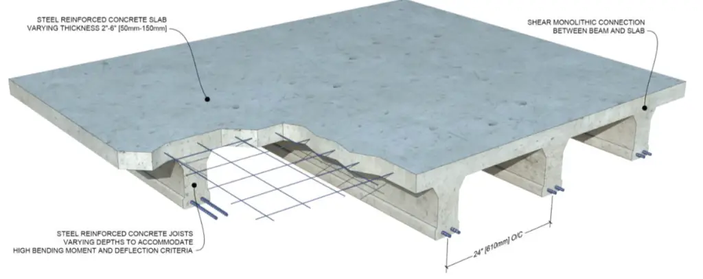
Therefore, the two major forms of construction of ribbed slabs are;
(1) Ribbed slab without permanent blocks
(2) Ribbed slab with permanent blocks
The major advantage of a ribbed slab with permanent blocks is the reduction in the quantity of formwork required, given the fact that the strength of the blocks is not usually assumed to contribute to the strength of the slab in design.
In Nigeria, clay hollow pots and sandcrete blocks have been successfully used, but on the rise is the use of polystyrene. Polystyrene offers the advantage of lightweight, improved fire resistance, and economy, at the expense of less rigidity compared to clay hollow pots or blocks.

In a generic sense, the use of polystyrene is to encourage savings in formwork costs, and may not be assumed to contribute to the strength of the floor in any way.

In this article, we are going to consider the design of a floor (see Figure 4) subjected to the following loading conditions;
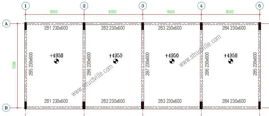
Finishes – 1.2 kN/m2
Partition allowance – 1.5 kN/m2
Imposed load – 2.5 kN/m2
fck = 30 Mpa, fyk = 500 Mpa, Concrete cover = 25 mm
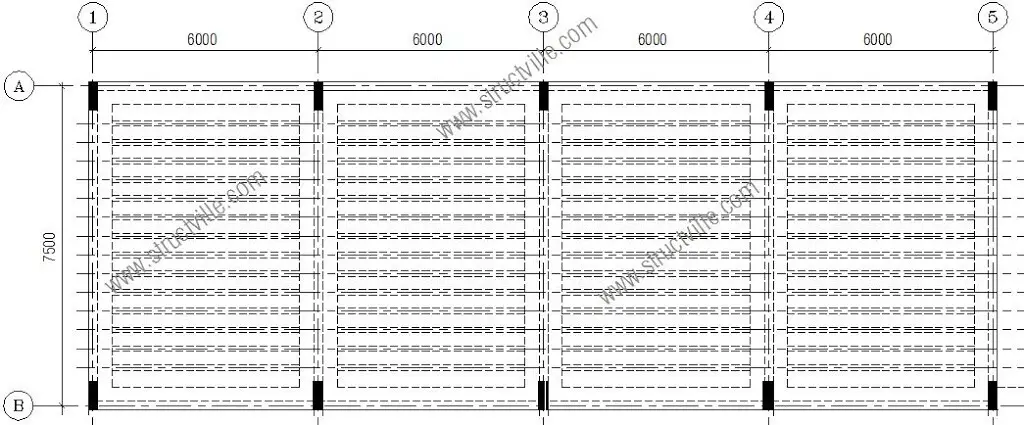
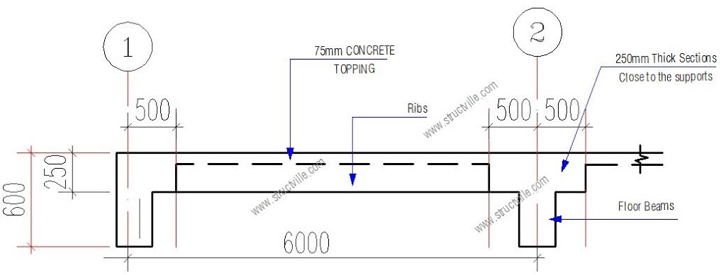
The structural engineer decided the scheme the structural layout as shown in Figure 5. The slab is made solid close to the supports, to enable adequate transmission of shear forces.
From a basic span/effective depth ratio of 26, let us choose a trial depth;
6000/26 = 231 mm
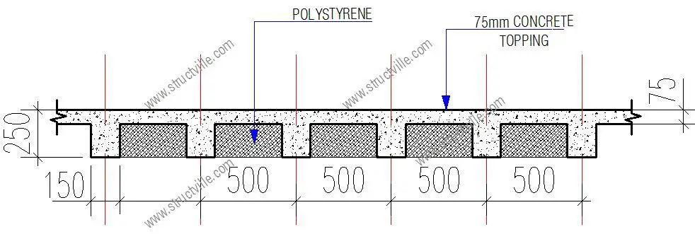
Let us try a total depth of 250 mm
Load Analysis
For 500mm c/c rib spacing;
Permanent Actions
Weight of topping: 0.075 × 25 × 0.5 = 0.9375 kN/m
Weight of ribs: 0.15 × 0.175 × 25 = 0.656 kN/m
Weight of finishes: 1.2 × 0.5 = 0.6 kN/m
Partition allowance: 1.5 × 0.5 = 0.75 kN/m
Weight of heavy-duty EPS (16 kg/m3) = 0.156 × 0.175 × 0.5 = 0.01365 kN/m
Total dead load gk = 2.95 kN/m
Variables Action(s)
Occupancy load qk: 2.5 × 0.5 = 1.25 kN/m
At ultimate limit state; 1.35gk + 1.5qk = 1.35(2.95) + 1.5(1.25) = 5.8575 kN/m
Structural Analysis
The design load per span at the ultimate limit state (FEd) is given by = 5.8575 kN/m × 6m = 35.145 kN/m
From clause 3.5.2.3 of BS 8110-1:1997, we can use the simplified method for structural analysis.
At the middle of span 1-2; M = 0.075 × 35.145 × 6 = 15.815 kNm
At support 2, MEd = -0.086 × 35.145 × 6 = 18.134 kNm
Designing the span as a T-beam;
MEd = 15.815 kN.m
Effective depth (d) = h – Cnom – ϕ/2 – ϕlinks
Assuming ϕ12 mm bars will be employed for the main bars, and ϕ10 mm bars for the stirrups (links)
d = 250 – 25 – (12/2) -10 = 209 mm
k = MEd/(fckbd2) = (15.815 × 10⁶)/(30 × 500 × 2092) = 0.024
Since k < 0.167, no compression reinforcement required
z = d[0.5+ √(0.25 – 0.882k)]
k’ = 0.024
z = d[0.5+ √((0.25 – 0.882(0.024))] = 0.95d = 198.55 mm
Depth to neutral axis x = 2.5(d – z) = 2.5(209 – 198.55) = 26.125 mm < 1.25hf (93.75mm)
Therefore, we design rib as a rectangular section
Area of tension reinforcement As1 = MEd / (0.87fyk z)
As1 = MEd / (0.87fyk z) = (15.815 × 10⁶) / (0.87 × 500 × 0.95 × 209) = 183 mm2
Provide 2H12 Bot (ASprov = 226 mm2)
Check for deflection
ρ = As,req /bd = 183 / (500 × 209) = 0.00175
ρ0 = reference reinforcement ratio = 10-3√(fck) = 10-3√(30) = 0.00547
Since ρ ≤ ρ0;
L/d = k [11 + 1.5√(fck) ρ0/ρ + 3.2√(fck) (ρ0 / ρ – 1)(3⁄2)]
k = 1.3
L/d = 1.3 [11 + 1.5√(30) × (0.00547/0.00175) + 3.2√(30) × [(0.00547 / 0.00175) – 1](3⁄2)]
L/d = 1.3[11 + 25.68 + 54.321] = 118.3
βs = (500 Asprov)/(fyk Asreq) = (500 × 226) / (500 × 183) = 1.23
beff/bw = 500/150 = 3.33
Therefore multiply basic length/effective depth ratio by 0.8
Therefore limiting L/d = 1.23 × 0.8 × 118.3 = 116.41
Actual L/d = 6000/209 = 28.708
Since Actual L/d (28.708) < Limiting L/d (116.41), deflection is satisfactory.
Design of Support 2;
MEd = 18.134 kN.m
Effective depth (d) = h – Cnom – ϕ/2 – ϕlinks
Assuming ϕ12 mm bars will be employed for the main bars, and ϕ10 mm bars for the stirrups (links)
d = 250 – 25 – (12/2) -10 = 209 mm
k = MEd/(fckbd2) = (18.134 × 10⁶)/(30 × 150 × 2092) = 0.0922
Since k < 0.167, no compression reinforcement required
z = d[0.5+ √(0.25 – 0.882k)]
k = 0.092
z = d[0.5+ √((0.25 – 0.882(0.092))] = 0.91d
Area of tension reinforcement As1 = MEd / (0.87fyk z)
As1 = MEd / (0.87fyk z) = (18.134 × 10⁶) / (0.87 × 500 × 0.91 × 209) = 219 mm2
Provide 2H12 Top (ASprov = 226 mm2)
Shear Design
Maximum shear force in the rib VEd = 0.6F = 0.6 × 35.145 = 21.087 kN
VRd,c = [CRd,c.k.(100ρ1 fck)(1/3) + k1.σcp]bw.d ≥ (Vmin + k1.σcp) bw.d
CRd,c = 0.18/γc = 0.18/1.5 = 0.12
k = 1 + √(200/d) = 1 + √(200/209) = 1.97 < 2.0, therefore, k = 1.97
Vmin = 0.035k(3/2) fck0.5
Vmin = 0.035 × (1.97)1.5 × 300.5 = 0.53 N/mm2
ρ1 = As/bd = 226/(150 × 209) = 0.0072 < 0.02; Therefore take 0.0072
VRd,c = [0.12 × 1.97 (100 × 0.0072 × 30 )(1/3)] × 150 × 209 = 20639.67 N = 20.639 kN
Since VRd,c (20.639 kN) < VEd (21.087 kN), shear reinforcement is required.
The compression capacity of the compression strut (VRd,max) assuming θ = 21.8° (cot θ = 2.5)
VRd,max = (bw.z.v1.fcd) / (cotθ + tanθ)
V1 = 0.6(1 – fck/250) = 0.6(1 – 30/250) = 0.528
fcd = (αcc fck) / γc = (0.85 × 30) / 1.5 = 17 N/mm2
Let z = 0.9d
VRd,max = [(150 × 0.9 × 209 × 0.528 × 17) / (2.5 + 0.4)] × 10-3 = 87.333 kN
Since < VEd < VRd,c < VRd,max
Hence Asw / S = VEd / (0.87 Fyk z cot θ) = 21087 / (0.87 × 500 × 0.9 × 209 × 2.5 ) = 0.103
Minimum shear reinforcement;
Asw / S = ρw,min × bw × sinα (α = 90° for vertical links)
ρw,min = (0.08 × √(fck)) / fyk = (0.08 × √30) / 500 = 0.000876
Asw/Smin = 0.000876 × 150 × 1 = 0.131
Maximum spacing of shear links = 0.75d = 0.75 × 209 = 156.75 mm
Provide H8mm @ 150 mm c/c as shear links.
Slab Topping
A142 BRC Mesh can be provided or H8 @ 250mm c/c
For more information on design and consultancy to accomplish the most challenging design brief, contact the author on info@structville.com. Thank you, and God bless you.







Weldone bro
Thank you very much.
Good work here Engr..
Good job!
Thank you very much. !
Please is it possible to have a slab of 9.9m width by 52.4m that will carry another slab and partitions up with out any supporting columns aside from the ones on the perimeter walls.
Yes it is possible.