In a practical medium- to long-span structures, post-tensioned slabs are economically competitive with reinforced concrete slabs and make up a sizable share of all prestressed concrete construction. The numerous drawbacks of reinforced concrete slabs (especially for long-span structures) are eliminated by prestressing.
In post-tensioned concrete construction, fresh concrete is cast around hollow ducts that are fitted to any desired profile. Normally, the steel tendons are unstressed in the ducts during the concrete pour. Nevertheless, they can also be threaded through the ducts at a later date. The tendons are tensioned (stressed) after the concrete reaches the desired strength at a later date. Tendons can either be stressed from both ends or from one end while the other end is anchored. At each stressed end, the tendons are then anchored.
After the tendons are anchored, the prestress is maintained by bearing the end anchorage plates onto the concrete, which places the concrete in compression during the stressing operation. Every time the cable’s direction changes, the post-tensioned tendons place a transverse force on the member.
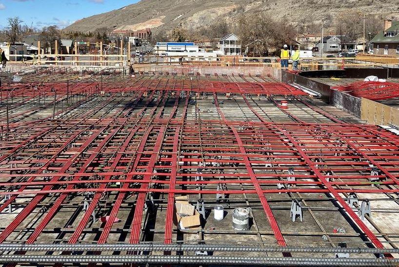
Post-Tensioned Slabs
In post-tensioned slabs, deflection, which is usually the controlling design consideration for concrete floors is controlled better. With an appropriate selection of prestressing/post-tensioning solutions, a designer is able to minimize or even completely eliminate deflection. As a result, thinner slab systems are possible, which can increase headroom or decrease floor-to-floor heights.
Additionally, prestress prevents cracking and can be utilized to create flooring that is watertight and devoid of cracks. Steel reinforcement layouts and fixes for prestressed slabs are often fewer and less complicated. As a result, pouring concrete and fixing steel reinforcements are simpler and faster. Additionally, prestressing reduces formwork costs and stripping times while enhancing punching shear. Conversely, prestressing frequently results in substantial axial shortening of slabs, necessitating special attention to the details of movement joints.
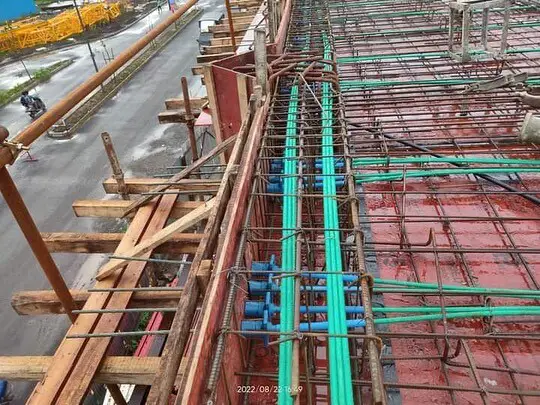
Post-tensioning is usually done on prestressed slabs using draped tendons. Flat-ducted tendons with five or fewer strands in a flat sheath and fan-shaped anchorages are frequently used, as shown in Figure 2. The use of small, portable hydraulic jacks allows for the one-at-a-time stressing of individual strands. The flat ducts allow for maximal tendon eccentricity and drape while being structurally effective. In order to provide a bond between the steel and the concrete, these ducts are usually grouted after stressing.

Pre-stressed concrete slabs are typically thin in proportion to their span. A concrete slab may experience a high magnitude of deflections at full load or show excessive camber after transfer if it is too thin. The serviceability criteria for the member often dictate the initial choice of slab thickness.
The decision on the thickness of a slab is usually made using prior experience or suggested maximum span-to-depth ratios. Note that the initial choice of slab thickness, while useful as a starting point for design, does not always guarantee that serviceability requirements will be met.
Unbonded tendons are frequently used in a majority of post-tensioned slabs simply because they lower the cost of construction. Post-tensioned slabs provide a number of important advantages over reinforced concrete slabs, such as:
• Longer spans with fewer columns leading to flexibility in the positioning of partitions.
• Thinner slabs lead to saving in construction costs and reduced height of the building.
• Especially in the case of car parks, the virtually crack-free slabs are a great advantage to limit damage due to seepage of water with de-icing salts from melting snow.
Balanced Load Stage for Two-Way Slabs
Two-way panels bend into dish-shaped surfaces when subjected to transverse loads, as depicted in Figure 3. Because the slab is curved in both major directions, bending moments exist in each of those directions. Additionally, twisting moments that develop in the slab at all points other than the lines of symmetry resist a portion of the applied load.

Each prestressing tendon resists a portion of the applied load, and they are typically arranged in two directions parallel to the panel edges. The transverse force that is applied to the slab by the tendons in one direction adds to (or deducts from) the transverse load that is applied in the opposite direction by the tendons. The amount of the load to be borne by tendons in each direction for edge-supported slabs is more or less arbitrary; the only strict condition is that statics be met.
For flat slabs, tendons must carry the entire load from column line to column line in both directions. The concept of using the transverse forces produced by the draped tendons’ curvature to balance a portion of the applied load is advantageous from the perspective of managing deflections. Load balancing not only offers the foundation for creating a proper tendon profile but also makes it possible to calculate the prestressing force necessary to achieve zero deflection in a slab panel under the chosen balanced load.
It is important to know that the slab is essentially flat (has no curvature) at the balanced load and is only affected by the prestressing forces applied at the anchorages. Only uniform compression (P/A) in the directions of the orthogonal tendons is applied to a slab of uniform thickness. When the condition of the slab under the balanced load is confidently known, any suitable method can be used to determine the deflection caused by the unbalanced portion of the load.
Since only the unbalanced portion of the total service load must be taken into account and, unlike reinforced concrete slabs, prestressed slabs frequently do not crack at service loads, the calculation of the deflection of a prestressed slab is typically more accurate than that of a conventionally reinforced slab.
The external load that needs to be balanced typically makes up a significant amount of the sustained or permanent service load in order to minimize deflection issues. The sustained concrete stress (P/A), if all the permanent loads are balanced, is constant throughout the slab depth. There is little long-term load-dependent curvature or bending due to uniform creep strain caused by uniform compressive stress distribution.
Of course, bonded reinforcement limits creep and shrinkage and, if the steel is eccentric to the slab centroid, results in a change in curvature with time. Prestressed slabs typically contain a limited amount of bonded steel, therefore the time-dependent curve this restraint produces rarely results in appreciable deflection.
Potential serviceability issues may be indicated by the average concrete compressive stress after all losses. The prestress may not be enough to avoid or control cracking brought on by shrinkage, temperature changes, and unbalanced loads if P/A is too low. The average concrete compressive stress after all losses is subject to minimum limits that are outlined in some standards of practice. Prestressing levels for a two-way slab are typically in the range P/A = 1.2 – 2.6 MPa using flat-ducted tendons with four or more strands.
Axial deformation of the slab may be significant and cause distress in the supporting structure if the average prestress is high. Regardless of the typical concrete stress, the rest of the structure must be able to withstand and accommodate the shortening of the slab, but when P/A is high, the issue is made worse (Gilbert et al, 2017). It could be essential to use movement joints to separate the slab from rigid supports.
In particular, for slabs containing less than minimum quantities of conventional tensile reinforcement (i.e. less than around 0.15% of the slab’s cross-sectional area), the spacing of tendons in at least one direction shall not exceed the smaller of eight times the slab thickness and 1.5 m.
General Approach to the Design of Post-Tensioned Slab
After making an initial selection of the slab thickness, the second step in slab design is to determine the amount and distribution of prestress.
Usually, load balancing is employed to achieve this. The transverse stresses induced on a slab by the draped tendons in each direction balance out a portion of the load. The slab stays flat (without curvature) under the balanced load and is only susceptible to the resulting longitudinal compressive P/A stresses.
The remaining imbalanced load is taken into account when calculating service load behaviour, especially when estimating load-dependent deflections and determining how much cracking has occurred and how much crack control has been applied.
The complete factored design load must be taken into account at ultimate limit state conditions, where the slab behaviour is non-linear and superposition is no longer valid. The factored design moments and shears at each critical section must be computed and compared with the design strength of the section. Slabs are typically fairly ductile, and as the slab’s collapse load approaches, moments redistribute. Secondary moments can typically be disregarded in these circumstances.
Load Balancing

Consider the interior panel of the two-way edge-supported slab shown in Figure 4. The panel has parabolic tendons in both the x and y axes and is supported by walls or beams on all sides. The upward forces per unit area that the tendons in each direction exert if the cables are uniformly spaced in each direction are;
wpx = 8Pxzd.x/lx2 ——— (1)
and
wpy = 8Pyzd.y/ly2 ——— (2)
where Px and Py are the prestressing forces in each direction per unit width, and zd.x and zd.y are the cable drapes in each direction.
The uniformly distributed downward load to be balanced per unit area wbal is calculated as:
wbal = wpx + wpy ——— (3)
In practice, perfect load balancing is not possible, since external loads are rarely perfectly uniformly distributed. However, for practical purposes, adequate load balancing can be achieved (Gilbert et al, 2017). Any combination of wpx and wpy that satisfies Equation (3) can be used to make up the balanced load. The smallest quantity of prestressing steel will result if all the loads are balanced by cables in the short-span direction, i.e. wbal = wpy.
However, under unbalanced loads, serviceability problems in the form of unsightly cracking may result. It is often preferable to distribute the prestress in much the same way as the load is distributed to the supports in an elastic slab, i.e. more prestress in the short-span direction than in the long-span direction. The balanced load resisted by tendons in the short direction may be estimated by:
wpy = [lx4/(δly4 + lx4)] × wbal ——— (4)
where δ depends on the support conditions and is given by:
δ = 1.0 for 4 edges continuous or discontinuous
= 1.0 for 2 adjacent edges discontinuous
= 2.0 for 1 long-edge discontinuous
= 0.5 for 1 short edge discontinuous
= 2.5 for 2 long + 1 short edge discontinuous
= 0.4 for 2 short + 1 long edge discontinuous
= 5.0 for 2 long edges discontinuous
= 0.2 for 2 short edges discontinuous
Equation (4) is the expression obtained for that portion of any external load which is carried in the short-span direction if twisting moments are ignored and if the mid-span deflections of the two orthogonal unit-wide strips through the slab centre are equated.
With wpx and wpy selected, the prestressing force per unit width in each direction is calculated using Equations (1) and (2) as:
Px = wpxlx2/8zd.x ——– (5)
and
Py = wpyly2/8zd.y ——– (6)
Equilibrium dictates that the downward forces per unit length exerted over each edge support by the reversal of cable curvature (as shown in Figure 4) are:
wpxlx (kN/m) carried by the short-span supporting beams or walls
wpyly (kN/m) carried by the long-span supporting beams or walls
The total force imposed by the slab tendons that must be carried by the edge beams is, therefore:
wpxlxly + wpylylx = wballxly ——– (7)
and this is equal to the total upward force exerted by the slab cables.
Therefore, for this two-way slab system, to carry the balanced load to the supporting columns, resistance must be provided for twice the total load to be balanced (i.e. the slab tendons must resist wballxly and the supporting beams must resist wballxly). This requirement is true for all two-way floor systems, irrespective of construction type or material.
At the balanced load condition, when the transverse forces imposed by the cables exactly balance the applied external loads, the slab is subjected only to the compressive stresses imposed by the longitudinal prestress in each direction, i.e. σx = Px/h and σy = Py/h, where h is the slab thickness.
Post-Tensioned Slab Design Example
It is required to design an exterior panel of a 175 mm thick two-way floor slab of a commercial building. The rectangular panel is supported by monolithic beams at all edges and discontinuous on two adjacent sides. It supports an additional dead load of 2.5 kN/m2 apart from its self-weight and a live load of 4 kN/m2. The slab is post-tensioned in both directions using the draped parabolic cable profiles shown below. The level of prestressing required to balance a uniformly distributed load of 4 kN/m2 is required. Relevant material properties are fck = 40 MPa, fctm = 3.5 MPa, Ecm = 35,000 MPa, fpk = 1,860 MPa and Ep = 195,000 MPa.


Self weight of the slab = 25 × 0.175 = 4.375 kN/m2
Superimposed dead load = 2.5 kN/m2
Total dead load = 6.875 kN/m2
Live load = 4 kN/m2
The total load on the slab = 6.875 + 4 = 10.875 kN/m2
Solution
Load Balancing
Load balancing:
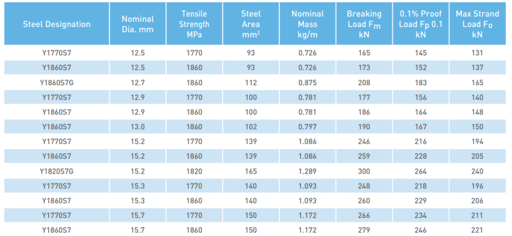
Flat-ducted tendons containing four 12.5 mm strands are to be used with a duct size of 75 mm × 19 mm.

With a 25 mm concrete cover to the duct, the maximum depth to the centre of gravity of the short-span tendons is:
dy = 175 − 25 − (19 − 7) = 138 mm (refer to the Figure above)
Eccentricity at the mid-span (short span) ex = 175/2 – 38 = 50 mm (say)
Eccentricity at the mid-span (long span) ey = 175/2 – 38 – 13 = 37 mm (say)
The cable drape in the short-span direction is, therefore:
zd.y = (50 + 0)/2 + 50 = 75 mm
The depth dx of the long-span tendons at mid-span is less than dy by the thickness of the duct running in the short-span direction, i.e. dx = 143 − 19 = 124 mm. The cable drape in the long-span direction is given by:
zd.x = (50 + 0)/2 + 37 = 62 mm
Self-weight of the slab = 25 × 0.175 = 4.375 kN/m2
If 40% of the live load is assumed to be sustained, then the total sustained load is:
wsus = 4.375 + 2.5 + (0.4 × 4.0) = 8.475 kN/m2
In this example, the effective prestress in the tendons in both directions balances an external load consisting of the self-weight and 10% of the superimposed dead load;
wbal = 4.375 + 0.1(2.5) = 4.625 kN/m2. The transverse load exerted by the tendons in the short-span direction is determined using Equation 4:
wpy = [lx4/(δly4 + lx4)] × wbal
Where δ = 1.0 for two adjacent edges discontinuous.
wpy = 94/(1.0 × 84 + 94) × 4.625 = 2.85 kN/m2
and the transverse load imposed by the tendons in the long-span direction is calculated;
wpx = wbal − wpy = 4.625 − 2.85 = 1.775 kN/m2
The effective prestress in each direction is obtained from Equations (1) and (2):
Pi = wpili2/8zd.i
Therefore,
Py = (2.85 × 82)/(8 × 0.075) = 304 kN/m
Px = (1.775 × 92)/(8 × 0.062) = 290 kN/m
Maximum force per tensioning = 137 kN
Assuming a 25% loss over the long term, the force per strand = 0.75 × 137 = 102.75 kN
For four strands = 4 × 102.75 = 411 kN
The number of strands required:
x-direction: nx = 290/411 = 0.7 (say 1 duct/m; comprising of 4 strands per duct),
Prestress provided = 102.75 × 4 = 411 kN/m
Load balanced, qx = (8 × 411 × 0.062)/92 = 2.516 kN/m2
y-direction: ny = 304/411 = 0.73, say (say 1 duct/m; comprising of 4 strands per duct)
Prestress provided = 102.75 × 4 = 411 kN/m
Load balanced, qy = (8 × 411 × 0.075)/82 = 3.853 kN/m2
Total load balanced = qx + qy = 2.516 + 3.853 = 6.369 kN/m2
Alternatively;
Both the time-dependent losses and friction losses must be estimated in order to determine the jacking forces and cable spacing in each direction. Assuming a 25% loss is used to account for all the losses;
Py = 304/0.75 = 405.3 kN/m
Px = 290/0.75 = 386.7 kN/m
Using four 12.5 mm strands/tendon, Ap = 372 mm2/tendon and the maximum jacking force/tendon is 137 × 4 = 548 kN, and the required tendon spacing in each direction (rounded down to the nearest 10 mm) is therefore:
sy = (1000 × 548)/405.3 = 1352 mm and
sx = (1000 × 548)/386.7 = 1417 mm
However, it is recommended that the spacing of tendons should not exceed 8h in the span. Therefore, the maximum spacing of the tendons can be taken as = 8 × 175 = 1400 mm.
We will select a tendon spacing of 1000 mm in each direction. This simply means that the tendons in the y-direction will balance slightly more load than previously assumed. With one tendon in each direction per metre width, the revised prestressing forces at the jack per metre width are Py = Px = 548 kN/m and at mid-span, after all losses, are:
Pm,t.y = 0.75 × 548 = 411 kN/m
and
Pm,t.x =0.75 × 548 = 411 kN/m
The load to be balanced is revised using Equations (1) and (2):
wpy = (8 × 411 × 0.075)/82 = 3.853 kPa
and
wpx = (8 × 411 × 0.062)/92 = 2.516 kPa
and therefore wbal = 3.853 + 2.516 = 6.369 kPa.
Estimate maximum moment due to unbalanced load
The maximum unbalanced transverse load to be considered for short-term serviceability calculations is:
wunbal = wsw + wG + ψ1wQ − wbal = 4.375 + 2.5 + (0.7 × 4.0) − 6.369 = 3.306 kPa
Under this unbalanced load, the maximum moment in the slab can be investigated;
The aspect ratio of slab = ly/lx = 9/8 = 1.125
The negative moment at the continuous edge (short span) = 0.056 × 3.306 × 82 = 11.84 kNm/m
The positive moment at midspan (short span) = 0.042 × 3.306 × 82 = 8.886 kNm/m
The negative moment at the continuous edge (long span) = 0.045 × 3.306 × 82 = 9.521 kNm/m
The positive moment at midspan (short span) = 0.034 × 3.306 × 82 = 7.193 kNm/m
Obviously, in this case, the maximum moment is 11.84 kNm/m
Check for cracking
The concrete stresses in the top and bottom fibres caused by the maximum moment after all losses are:
σc.top = − Pm,t.y/A + MCD/Z = [(411 × 103)/(175 × 103)] + [(11.84 × 10⁶)/(5.104 × 106)] = −2.35 + 2.319 = -0.031 MPa (compression)
σc.btm = − Pm,t.y/A – MCD/Z = −2.35 – 2.319 = -4.669 MPa (compression)
where A is the area of the gross cross-section per metre width (A = bh = 175 × 103 mm2/m) and Z is the section modulus per metre width (Z = I/y = 5.104 × 106 mm3/m). Both the top and bottom stresses are relatively low. Even though the moment used in these calculations is an average and not a peak moment, if cracking does occur, it will be localised and the resulting loss of stiffness will be small. Deflection calculations may be based on the properties of the uncracked cross-section.
Maximum total deflection
The deflection at the mid-panel of the slab can be estimated using the so-called crossing beam analogy, in which the deflections of a pair of orthogonal beams (slab strips) through the centre of the panel are equated. The fraction of the unbalanced load carried by the strip in the short-span direction is given by an equation similar to Equation (4).
wunbal.x = 94/(1.0 × 94 + 84) × 3.306 = 0.615 × 3.306 = 2.035 kN/m
and with the deflection coefficient β taken as 3.5/384, the corresponding short-term deflection at mid-span of this 1 m wide slab strip in the short-span direction through the mid-panel (assuming the variable live load is removed from the adjacent slab panel) is approximated by:
v0 = 3.5wunbal,yly4/384EcmI = (3.5 × 2.035 × 80004)/(384 × 35000 × 446.614 × 106) = 4.86 mm
The sustained portion of the unbalanced load on the slab strip is:
[lx4/(δly4 + lx4)] × (wsw + wG + y2wQ – wbal) = 0.61 × [4.375 + 2.5 + (0.4 × 4.0) – 6.369] = 1.28 kPa
and the corresponding short-term deflection is:
vsus.0 = 1.28/2.035 × v0 = 3.056 mm
Assuming a final creep coefficient φ(∞,t0) = 2.5 and conservatively ignoring the restraint provided by any bonded reinforcement, the creep-induced deflection may be estimated using:
vcc = 2.5 × 3.056 = 7.64 mm
The final shrinkage strain is assumed to be εcs = 0.0005. The shrinkage curvature κcs is non-zero wherever the eccentricity of the steel area is non-zero and varies along the span as the eccentricity of the draped tendons varies.
A simple and very approximate estimate of the average final shrinkage curvature is;
κcs = 0.3εcs/h = (0.3 × 0.0005)/175 = 0.857 × 10⁻⁶ mm-1
The average deflection of the slab strip due to shrinkage is given by Equation 12.8:
vcs = 0.090 × 0.857 × 10-6 × 80002 = 4.936 mm
The maximum total deflection of the slab strip is therefore:
vtot = v0 + vcc + vcs = 4.86 + 7.64 + 4.936 = 17.436 mm = span/456 < Span/250
Check flexural strength
It is necessary to check the design strength of the slab. As previously calculated, the dead load is 4.375 + 2.5 = 6.875 kN/m2 and the live load is 4.0 kN/m2. The factored design load is:
wEd = 1.35(6.875) + 1.5(4) = 15.28 kN/m2
The negative moment at the continuous edge (short span) = 0.056 × 15.28 × 82 = 54.763 kNm/m
The positive moment at midspan (short span) = 0.042 × 15.28 × 82 = 41.07 kNm/m
The negative moment at the continuous edge (long span) = 0.045 × 15.28 × 82 = 44kNm/m
The positive moment at midspan (short span) = 0.034 × 15.28 × 82 = 33.25 kNm/m

A safe lower bound solution to the problem of adequate strength is obtained if the design strength of the slab at this section exceeds the design moment. The resistance per metre width of the 175 mm thick slab containing tendons at 1000 mm centres (i.e. Ap = 372 mm2/m) at an effective depth of 138 mm can be obtained by considering the figure above.
The stress in the tendon caused by the effective prestressing force Pm,t = 411 kN is:
σpm,t = Pm,t/Ap = (411 × 103)/372 = 1105 MPa
EN1992-1-1 permits the design stress in the tendon at the strength limit state to be taken as:
σpud = σpm,t + 100 = 1205 MPa
and therefore the tensile force in the steel is Fptd = 448.26 kN (= Fcd).
x = Fptd/ ηfcdλb = (448.26 × 10³ )/(1.0 × 26.67 × 0.8 × 1000) = 21 mm
Such an analysis indicates that the cross-section is ductile, with the depth to the neutral axis of x1 = 21 mm (or 0.152d).
MRd1 = σpudAp × [dp− (λx)/2)]
MRd1 = 1205 × 372 × [138 − (0.8 × 21)/2)] × 10-6 = 58.09 kN/m
This shows that no additional reinforcement is required. However, 12 mm diameter non-prestressed reinforcing bars in the y-direction at 450 mm centres can be provided all over the slab.
Reference
Gilbert R.I, Mickleborough N.C. and Ranzi G. (2017): Design of Prestressed Concrete to Eurocode 2 (2nd Edition). CRC Press, Taylor and Francis,




weldone my Engr, you are really doing great, may God bless you.