8.7 C
New York
Thursday, May 1, 2025
Home Blog Page 29

Effect of Groundwater Table on the Bearing Capacity of Shallow Foundations

Bearing capacity is the maximum load a soil profile can withstand before undergoing excessive deformation and final shear failure. It is well understood that the depth of the groundwater table can affect the strength of soils, but a high water table does not necessarily indicate that the soil is weak as sometimes misunderstood. However, the presence of groundwater in soils can reduce the strength due to the way water affects the unit weight of soils and the shear strength parameters – cohesion (c) and angle of internal friction (ϕ).

If we consider Terzaghi’s general bearing capacity equation;

qult = cNc + γDfNq + 0.5γbNγ —— (1)

We will discover that the equation contains terms for cohesion (c), angle of internal friction (ϕ), and unit weight of the soil (γ). The bearing capacity factors Nc, Nq, and Nγ depend on the angle of internal friction. When the soil is submerged, the effective unit weight (γ′) is to be used in the computation of bearing capacity.

γ′ = γsat – γw —— (2)

Where;
γ′ = Effective unit weight of the soil
γsat = saturated unit weight of the soil
γw = Where is the unit weight of water

As can be seen from Equation (2), the effective unit weight γ′ is about half the saturated unit weight; consequently, there will be about 50% reduction in the value of the corresponding term in the bearing capacity formula. Similarly, the effective stress parameters, c′ and φ′, obtained from an appropriate test in the laboratory, on a saturated sample of the soil, are to be used. It should be noted that water also affects the shear strength parameters c′ and φ′ but their effects are usually so small that they are ignored.

high water table in foundations
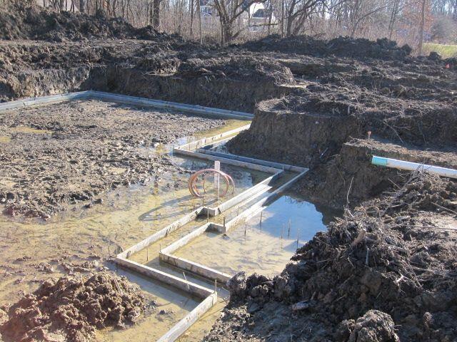
Foundation construction in an area of high water table

It should be now obvious that the location of the groundwater table and its seasonal fluctuations have an effect on the bearing capacity of a foundation. If the water table is at a great depth from the base of the foundation, there will be no effect or reduction in the bearing capacity.

In the design of footings, the minimum depth below the base of the footing at which the water table is not expected to have an effect on the bearing capacity is set at a value equal to the width of the footing. This is because the maximum depth of the zone of shear failure below the base is not expected to exceed this value ordinarily.

However, if the water table is above this level, there will be a reduction in the bearing capacity. If the water table is at the level of the base of the footing, γ′ is to be used for γ in the third term, which indicates the contribution of the weight of the soil in the elastic wedge beneath the base of the footing, since the entire wedge is submerged.

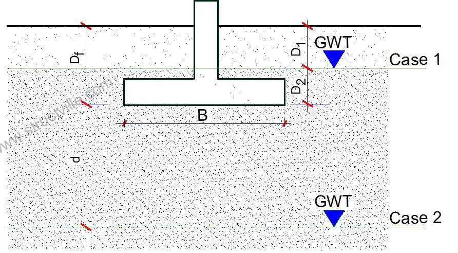
Therefore, three cases are usually considered in the design of footings for the effect of the water table;

modification of bearing capacity for high groundwater table
Modification of bearing capacity for water table

Case 1: If the water table is located so that 0 ≤ D1 ≤ Df (water table above the footing level), the factor q in the bearing capacity equations takes the form;
q = effective surcharge = D1γ + D2sat – γw)

Case 2: If the water table is located so that 0 ≤ d ≤ B (water table at footing level or within the depth d), the factor q in the bearing capacity equations takes the form;
q = effective surcharge = γDf

The factor γ in the last term of the bearing capacity equation will have to be replaced by the factor;

= γ’ + d/B(γ – γ’)

Case 3: When the water table is located such that d ≥ B, the water table will have no effect on the bearing capacity.

Worked Example on Effect of Groundwater Table

A footing 2 m square, subjected to a centric vertical load, is located at a depth of 1.0 m below the ground surface in a deep deposit of compacted sand, φ′ = 30°, and γsat = 19 kN/m3. Determine the allowable bearing capacity using Terzaghi’s theory when the water table is at;

(a) at 5m below the ground surface
(b) at the ground surface
(c) at the bottom of the base of the footing, and
(d) at 1 m below the base

Solution

For a square footing according to Tezarghi’s theory;

qult = γDfNq + 0.4γbNγ

Nq = 22.46
Nγ =19.13

(a) If the water table is at 5m below the surface, d (4 m) > B (2 m), hence the water table will have no effect on the bearing capacity;
qult = γDfNq + 0.4γbNγ = (19 × 1 × 22.46) + (0.4 × 19 x 2 x 19.13) = 717.516 kN/m2

(b) If the water table is at the ground surface;
γDf = Dfsat – γw) = 1m (19 – 9.81) = 9.19 kN/m2
γ′ = γsat – γw = (19 – 9.81) = 9.19 kN/m3
qult = γDfNq + 0.4γ’bNγ = (9.19 × 22.46) + (0.4 × 9.19 x 2 x 19.13) = 347.05 kN/m2

(c) If the water table is at the bottom of the footing;
γDf = (1m × 19) = 19 kN/m2
γ′ = γsat – γw = (19 – 9.81) = 9.19 kN/m3
qult = γDfNq + 0.4γ’bNγ = (19 × 22.46) + (0.4 × 9.19 x 2 x 19.13) = 567.38 kN/m2

(d) If the water table is at 1m below footing;
γDf = (1m × 19) = 19 kN/m2
= γ’ + d/B(γ – γ’) = 9.19 + [(1/2) × (19 – 9.19)] = 14.095 kN/m3
qult = γDfNq + 0.4bNγ = (19 × 22.46) + (0.4 × 14.095 x 2 x 19.13) = 642.45 kN/m2


From the results above, the following was observed;

(1) When the water table is at the ground surface, the bearing capacity reduces by 51.63%.
(2) When the water table is at the bottom of the footing, the bearing capacity reduces by 20.92%.
(3) When the water table is at 1m below the footing, the bearing capacity reduces by 10.46%.

Stress Path Approach for Shear Strength of Soils

During the shear strength test of soils using a triaxial machine, one of the major ways of monitoring stress changes is by showing the Mohr’s stress circles at different stages of loading/unloading. However, this may be difficult to plot as well as confusing when a number of circles are to be shown in the same diagram. In this case, a stress path may be used to show the changes in stress in the soil or material.

Triaxial testing machine
Fig 1: Typical triaxial testing machine

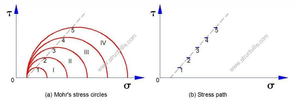
A Stress Path is therefore a curve or a straight line which is the locus of a series of stress points showing the changes in stress in a test specimen or in a soil element in-situ, during loading or unloading, engineered as in a triaxial test in the former case or caused by forces of nature as in the latter. This idea that the locus of points depicting the maximum shear stress acting on a soil sample can be drawn as a stress path in place corresponding Mohr’s circle was suggested by Lambe and Whitman (1969). This is shown in Fig 2.

stress path
Fig. 2: Stress path for the case of σ1 increasing and σ3 constant

The co-ordinates of the points on the stress path are (σ1 + σ3)/2 and (σ1 – σ3)/2.

When stress paths only are plotted then the axes of the diagram are really particular values of the shear stress τ and normal stress σ. These values are commonly referred to as q and p. Mean stress, p, is the average stress on a body or the average of the orthogonal stresses in three dimensions. Deviatoric stress, q, is the shear or distortional stress or stress difference on a body. p and q are called stress invariants and do not depend on the axis system chosen.

p = mean stress = (σ1 + σ3)/2
q = deviator stress = (σ1 – σ3)/2

If q is considered in terms of effective stress;

(σ’1 – σ’3)/2 = [(σ1 – u) – (σ3 – u)]/2 = (σ1 – σ3)/2

This shows that q is the same regardless of whether total stresses or effective stresses are being considered. In other words, the deviatoric (shear) stress is unaffected by pore water pressure. Since q is equal to the radius of the Mohr circle this means that the total and effective Mohr circles must always have the same size

By implication, either the effective stresses or the total stresses may be used for plotting stress paths. The basic types of stress path and the co-ordinates are:

(a) Effective Stress Path (ESP) (p, q) = [(σ’1 + σ’3)/2, (σ’1 – σ’3)/2]
(b) Total Stress Path (TSP) (p, q) = [(σ1 + σ3)/2, (σ1 – σ3)/2]
(c) Stress path of total stress less static pore water pressure (TSSP) (p, q) = [(σ1 + σ3)/2 – u0, (σ1 – σ3)/2]

Where u0 is the static pore water pressure.

The static pore water pressure is zero in the conventional triaxial test, and (b) and (c) coincide in this case. But if backpressure is used in the test, u0 equals the backpressure. For an in-situ element, the static pore water pressure depends upon the level of the groundwater table. Typical stress paths for triaxial compression and extension tests (loading as well as unloading cases) are shown in Fig. 3.

Stress path for triaxial compression and extension
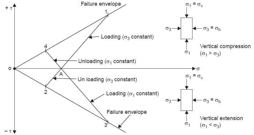
Fig 3: Typical stress paths for triaxial compression and extension tests (Venkatramaiah, 2006)

A-1 is the effective stress path for conventional triaxial compression test during loading. (Δσv = positive and Δσh = 0, i.e., σh is constant). A typical field case is a footing subjected to vertical loading.

A-2 is the unloading case of the triaxial extension text (Δσh = 0 and Δσv = negative). Foundation excavation is a typical field example.

A-3 is the loading case of the triaxial extension test (Δσv = 0 and Δσh = positive). Passive earth resistance is represented by this stress path.

A-4 is the unloading case of the triaxial compression test (Δσu = 0 and Δσh = negative). Active earth pressure on retaining walls is the typical field example for this stress path.

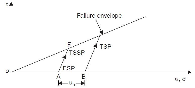
Figure 4 shows the typical stress paths for a drained test. Point A corresponds to the stress condition with only the confining pressure acting (σ1 = σ3 and τ = 0). Point F represents failure. Stress paths for effective stresses, total stresses, and total stresses less static pore water pressure are shown separately in the same figure.

drained test
Fig. 4: Stress paths for drained test (Venkatramaiah, 2006)

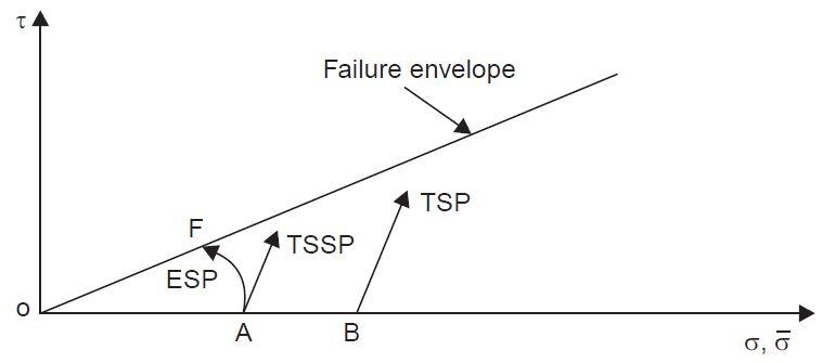
Figure 5 shows the stress paths for a consolidated undrained test on a normally consolidated clay.

stress path in consolidated undrained test
Fig 5: Stress paths for consolidated undrained test on a normally consolidated clay (Venkatramaiah, 2006)

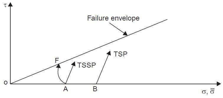
Figure 6 shows the stress paths for a consolidated undrained test on an overconsolidated clay.

stress path in unconsolidated clay
Fig 6: Stress paths for consolidated undrained test on an overconsolidated clay (Venkatramaiah, 2006)

Stress path approach enables the engineer to predict and monitor the shear strength mobilized at any stage of loading/unloading in order to ensure the stability of foundation soil.

Procedure for Plotting Stress Paths

A summary of the procedure for plotting stress paths is as follows:

  1. Determine the loading conditions drained or undrained, or both.
  2. Calculate the initial loading values of p’o, po, and qo.
  3. Set up a graph of p’ (and p, if you are going to also plot the total stress path) as the abscissa and q as the ordinate. Plot the initial values of (p’o, qo) and (po, qo).
  4. Determine the increase in stresses ∆σ1, ∆σ2, and ∆σ3. These stresses can be negative.
  5. Calculate the increase in stress invariants ∆p’, ∆p, and ∆q. These stress invariants can be negative.
  6. Calculate the current stress invariants as p’ = p’o + ∆p’ , p = po + ∆p, and q = qo + ∆q. The current value of p’ cannot be negative, but q can be negative.
  7. Plot the current stress invariants (p’, q) and (p, q).
  8. Connect the points identifying effective stresses, and do the same for total stresses.
  9. Repeat items 4 to 8 for the next loading condition.
  10. The excess porewater pressure at a desired level of deviatoric stress is the mean stress difference between the total stress path and the effective stress path. Remember that for a drained loading condition, ESP = TSP, and for an undrained condition, the ESP for a linear, elastic soil is vertical.

Sources:

Venkatramaiah, C. (2006): Geotechnical Engineering. New Age Publishers, India
Budhu M. (2010): Soil mechanics and foundations (3rd Edition). John Wiley and Sons, USA

Design of Hollow Steel Section Connections

It is common knowledge that a well-designed hollow steel section has lesser material weight and higher strength to weight ratio when compared with an equivalent open section profile such as a universal beam (I-section) or universal column (H-section). However, an important aspect of hollow steel section design is in the design of the connections. The design of hollow steel section connection in terms of joint resistance and cost fabrication is affected considerably by member sizing since the sections are usually welded to each other.

The most common types of hollow steel sections employed in design are;

  • Circular hollow section (CHS)
  • Square hollow section (SHS)
  • Rectangular hollow section (RHS)

Joint Geometry

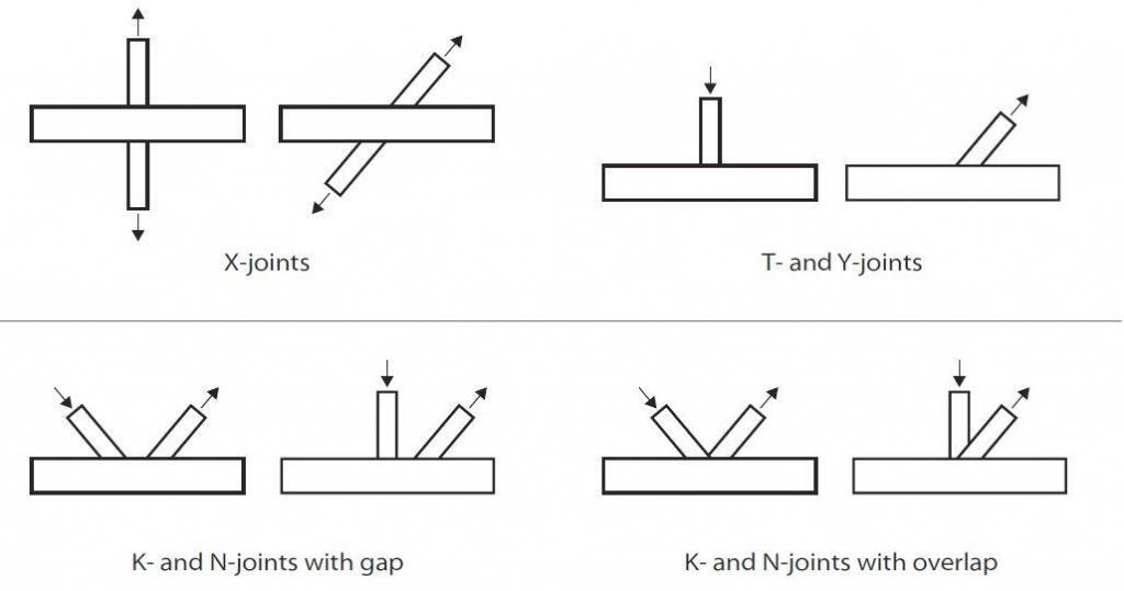
The most common types of hollow section joint configuration are;

  • X-joints
  • T- and Y-joints
  • K- and N-joints with gap
  • K- and N-joints with overlap

These configurations are shown in Figure 1.

different joint configurations for hollow sections
Figure 1: Different configurations for hollow sections

Generally, it is recommended that the angle between the chord and a bracing or between two bracings should be between 30° and 90° inclusive. If the angle is less than 30° then:

a) The designer must ensure that a structurally adequate weld can be made in the acute angle
b) The joint resistance calculation should be made using an angle of 30° instead of the actual angle

When K- or N-joints with overlapping bracings are being used, the overlap must be made with:
• Partial overlap where the first bracing runs through to the chord, and the second bracing sits on both the chord and the first bracing, or
• Sitting fully on the first bracing.

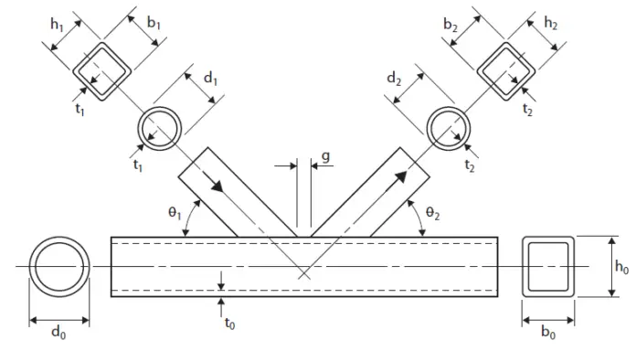
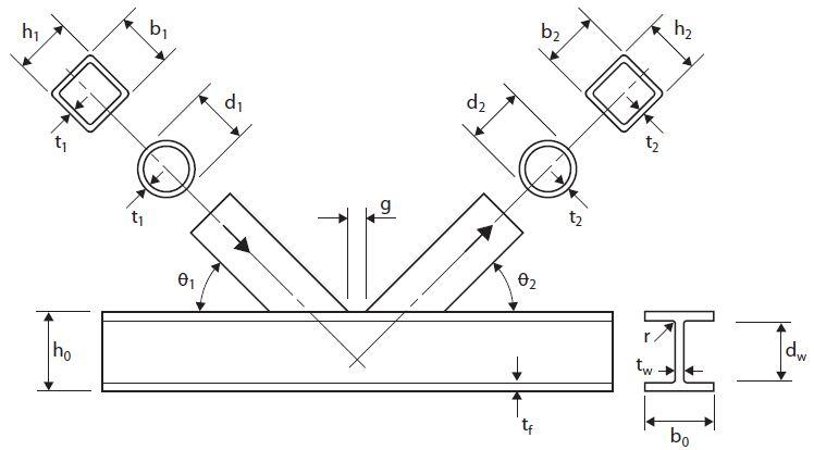
The typical joint geometry symbols used in the design are shown in Figure 2 and 3;

image
Figure 2: Circular and rectangular chord symbols
other sections
Figure 3: I- or H-chord symbols


Multi-planar Joints

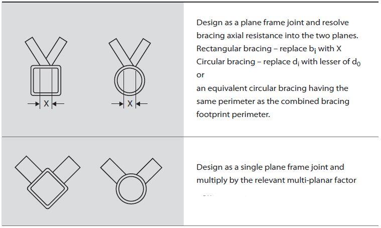
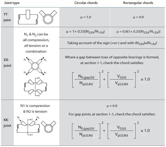
Multi-planar joints are typically found in triangular and box girders.To determine whether a joint should be considered as a multi-planar or a single planar joint refer to Figure 4. By applying the multiplanar factor, μ (Figure 5) to the calculated chord face deformation, you can use the same design formulae as planar joints.

planar joints
Figure 4: Multi-planar joints

The planar factors shown in the figure below have been determined for angles between the planes of 60° to 90°.

planar factors
Figure 5: Multi-planar factors

Welding of Hollow Steel Section Connections

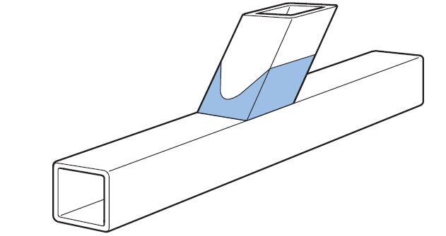
When a bracing member is under load, a non-uniform stress distribution is present in the bracing close to the joint, see Figure 6. Therefore, to allow for this non-uniformity of stress, the welds connecting the bracing to the chord must be designed to have sufficient resistance. Normally, the weld should be around the whole perimeter of the bracing using a buttweld, fillet-weld, or a combination of the two.

stress distribution at a joint
Figure 6: Typical localised stress distribution at a joint

For bracing members in a lattice construction, the design resistance of a fillet-weld should not normally be less than the design resistance of the member. This is satisfied if the throat size (a) is at least equal to or larger than 1.1 times the width of the section, provided you use electrodes with an equivalent strength grade to the steel (both yield and tensile strength).

The weld resistance can also be verified from the simplified method for design of fillet weld EN 1993:1-8 clause 4.5.3.3;

Fw,Ed < Fw,Rd

Where;
Fw,Ed is the design value of the weld force per unit length
Fw,Rd is the design weld resistance per unit length

For a more efficient weld, you can use the directional method from EN 1993:1-8 clause 4.5.3.2.

Fabrication

In a lattice-type construction, the largest fabrication cost is the end preparation and welding of the bracings, and the smallest is the chords. As a general rule, the number of bracing members should be as small as possible. The best way to achieve this is using K- type bracings, rather than N-type bracings. Hollow sections are much more efficient in compression than open sections, angles or channels, meaning compression bracings do not need to be as short as possible. This makes the K-type bracing layout much more efficient.

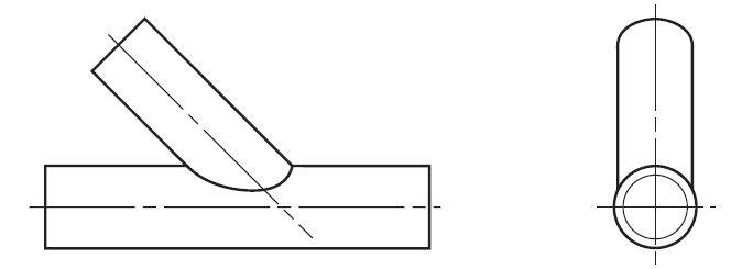
In circular chords, the ends of each bracing in a girder has to be profile-shaped to fit around the curvature of the chord member (see Figure 7), unless the bracing is very much smaller than the chord. Also, for overlap joints with circular bracings and chords, the overlapping bracing has to be profile shaped to fit to both chord and the overlapped bracing.

CONNECTION TO A CIRCULAR CHORD
Figure 7: Connections to a circular chord

Joint Design Parameters and Resistance

The various geometric parameters of the joint have an effect on its resistance. This is dependant on the:


• joint type (single bracing, two bracings with a gap or an overlap) and,
• type of forces on the joint (tension, compression, moment).

The following points should be considered in the design of hollow steel section connections.


(1) The joint

(a) The joint resistance will always be higher if the thinner member sits on and is welded to the thicker member, rather than the other way around.
(b) Joints with overlapping bracings will generally have a higher resistance than joints with a gap between the bracings.
(c) The joint resistance, for all joint and load types (except fully overlapped joints), will be increased if small thick chords rather than larger and thinner chords are used.
(d) Joints with a gap between the bracings have a higher resistance if the bracing to chord width ratio is as high as possible. This means large thin bracings and small thick chords.
(e) Joints with partially overlapping bracings have a higher resistance if both the chord and the overlapped bracing are as small and thick as possible.
(f) Joints with fully overlapping bracings have a higher resistance if the overlapped bracing is as small and thick as possible. In this case, the chord has no effect on the joint resistance.
(g) On a size-for-size basis, joints with circular chords will have a higher resistance than joints with rectangular chords.


(2) The overall girder requirements

(a) The overall girder behaviour, e.g. lateral stability, is increased if the chord members are large and thin. This also increases the compression chord strut resistance, due to its larger radius of gyration.
(b) Consideration must also be given to the fabrication costs.

Joint Failure Modes

Joints have a number of different failure modes depending on the joint type, the geometric parameters of the joint and the type of loading. These various types of failure are described below;

(a) Chord Face Failure
This is the most common failure mode for joints with a single bracing, and for K- and N-joints with a gap between the bracings if the bracing to chord width ratio (β) is less than 0.85.

chord face failure
Figure 8: Chord face failure

(b) Chord sidewall failure
This is the yielding, crushing, or instability (crippling or buckling) of the chord sidewall or web under the compression brace member. Also includes sidewall yielding if the bracing is in tension. Usually only occurs when the bracing to chord width ratio (β) ratio is greater than about 0.85, especially for joints with a single bracing.

chord side wall failure
Figure 9: Chord sidewall failure

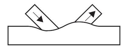
(c) Chord shear
This is found typically in the gap of a K-joint. The opposite vertical bracing force causes the chord to shear. It does not often become critical, but can if you use rectangular chords with the width (b0) greater than the depth (h0). If the validity limits are met then chord shear does not occur with circular chords.

chord shear
Figure 10: Chord Shear

(d) Chord punching shear
This can be caused by a crack initiation in the chord face leading to rupture failure of the chord. It is not usually critical, but can occur when the chord width to thickness ratio (2γ) is small.

chord punching shear
Figure 11: Chord Punching shear

(e) Bracing Effective Width
This is non-uniform stress distribution in the brace causing a reduced effective brace width. This reduces the effective area carrying the bracing force. It is mainly associated with rectangular chord gap joints with large β ratios and thin chords. It is also the predominant failure mode for rectangular chord joints with overlapping rectangular bracings.

bracing effective width
Figure 12: Bracing Effective Width

(f) Chord or bracing localised buckling
Due to the non-uniform stress distribution at the joint, reducing the effective area carrying the bracing forces. This failure mode will
not occur if the validity ranges are met.

localised buckling
Figure 13: Chord or bracing localised buckling

(g) Shear of overlapping bracings
Due to the bracing’s horizontal force causing shearing at the chord face. This failure mode becomes critical for large overlaps, over 80% or 60%, depending on if the hidden toe of the overlapped bracing is welded to the chord.

overlapping braces
Figure 14: Shear of overlapping bracings

Disclaimer:
The contents of this article are culled from;
TATA Steel: Design of welded joints Celsius®355 and Hybox®355

Webinar on Structural Design of Complex 3D Roof Trusses

We are pleased to announce our Webinar for the month of July, 2021. The details of the webinar are as follows;

Topic: Structural Design of Complex 3D Roof Trusses
Date: Saturday 10th July 2021
Time: 7:00 pm to 9:00 pm (West African Time)
Fee: NGN 3,000 only ($ 8.00 USD)
Platform: Zoom
To register click HERE

3d roof truss

Major Features:
(1) Design of complex 3D roof trusses, especially for irregularly shaped building
(2) Design of curved roof trusses

Learning Objectives:
(1) How to prepare the general arrangement (layout) of roof trusses
(2) How to select and model structural members of roof trusses in 3D
(3) How to model curved roof members on Staad Pro
(4) How to apply gravity, wind load, and load combinations on roof trusses
(5) How to design and detail roof truss members and their connections
(6) Free design materials and drawings

To register for this webinar, click HERE

Underpinning of Foundations

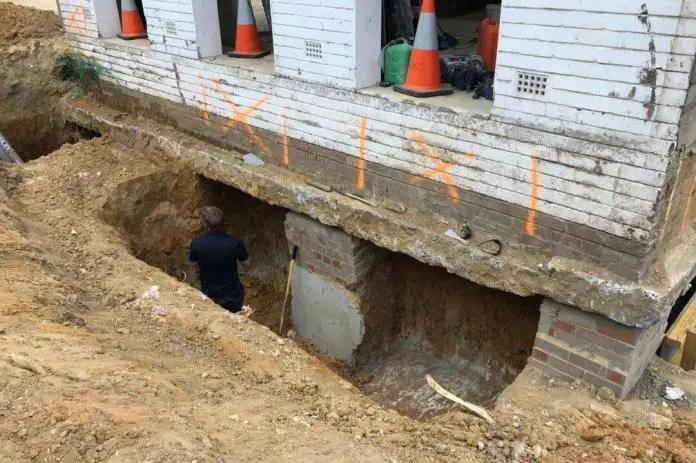
Underpinning is a process used to rectify distress caused to a building by excessive movement of its foundation, to extend foundations into the ground to facilitate future construction work, to accommodate additional load applied to an existing building, to allow the adjacent ground to be lowered, or to change the support system (BS 8004-2015).

According to BS 8004-1986, the two major objectives of underpinning are to transfer the load carried on a foundation from its existing bearing level to a new level at a lower depth and to limit the settlement of foundations.

Types of Underpinning

According to BS 8004, the major types of underpinning include:

  1. Extending the depth of strip or pad footings (continuous underpinning constructed in sections usually not exceeding 1.2 m);
  2. Constructing piles that are drilled through the foundations;
  3. Constructing ground beams beneath walls formed by stooling or needling and supported by piers or piles;
  4. Constructing ground beams beside walls supported by piers or piles with needles and/or load transfer by stressing or other details to transfer the load to the new support.

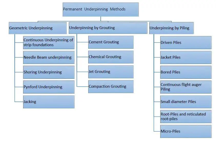
Generically, the types of permanent underpinning can be seen in the chart below;

Types of underpinning

Before underpinning is considered and resorted to, it is very important for an experienced and competent person to carry out a full investigation to determine whether the purpose of carrying out the underpinning will be achieved. The choice of underpinning system is expected to consider the loads carried, the sensitivity of the ground and the existing structure, nearby structures, and the working conditions.

The ground investigation should determine the conditions responsible for any excessive movement so that appropriate underpinning measures will be taken. Furthermore, the general nature of the ground, load-bearing capacity, and the effects of adjoining foundations should be determined before the full design of the underpinning system can be done.

Furthermore, the structure to be underpinned should be carefully investigated. All indications of distress, differential foundation settlement, and weak planes which may be accentuated during the process of underpinning should be identified and temporarily supported and/or strengthened before the underpinning can commence.

Design for Underpinning

Underpinning systems should be designed in accordance with good soil mechanics practice taking into account all vertical and lateral loads imposed upon them, including particularly transient conditions that may arise during construction. The design of underpinning should be done according to EN 1997-1 and Clause 4 of BS 5400:2015. The structural design of underpinning for spread and pile foundations should conform to relevant standards.

It is important to note that underpinning may alter or deepen only part of a foundation if only part is to be underpinned or is shown to be unstable. The designer has to be satisfied that the whole foundation including that part modified by underpinning will continue to perform satisfactorily.

If the changed support conditions will inevitably give rise to excessive differential movement, jacks may be installed temporarily or permanently to correct this. Such elaborate arrangements are rarely required except when underpinning particularly heavy walls or piers. If the whole of a structure is subsiding unevenly, for example, a building on a bed of made-up ground of variable thickness, partial underpinning will be unsuccessful and the whole structure has to be underpinned.

Construction Processes for Underpinning

Live Load Reduction
Before the commencement of excavation, it is important to reduce the live loads on the walls and columns of the structure as practically as possible. This is more important when the live load is large in relation to the dead load.

Excavation
The area of open excavations should not exceed 25% of the building’s footprint. This limit should be reduced if the building comprises a number of isolated piers.

Support of Excavations
All excavations necessary for underpinning should be properly supported using struts of steel, timber, concrete, or other adequate temporary or permanent works as adequately designed using standard geotechnical processes.

Underpinning legs
If the underpinning will not give rise to excessive ground pressure, the underpinning process should be carried out in a series of legs. The length of each leg should depend on the general character and condition of the ground and the structure to be underpinned, the intensity of the loading, and the nature of the ground below. In normal brick or stone walls, each leg should be 1000 mm to 1400 mm in length. This length can be increased in walls that are capable of arching.

legs in foundation underpinning

Each series of legs should be planned to provide sufficient support between the legs under construction and to ensure that the loads from the unsupported portions of the wall are distributed throughout the length of the wall.

If underpinning is required to take care of excessive settlement, or if the allowable settlement is likely to be exceeded during the underpinning operations, the structure to either side of an underpinning leg should be needled and the load transferred to temporary bearings capable of carrying the additional load. Alternatively, stooled reinforced concrete beam might be introduced before the underpinning can commence.

If the width of the foundation to be underpinned is greater than 1000 mm, it is advisable to leave the outer half more than 150mm below the underside of the foundation to facilitate the pinning up of the furthest part.

How to Determine the Depth of Foundation

Foundations are substructure elements that transmit the superstructure load of a structure to the final bearing soil layer/stratum. The depth of a foundation is an important parameter that influences the performance of the structure. There are no strict rules or direct formulas for determining the depth of a foundation, but there are important factors that must be considered before the final depth of a foundation is selected.

The first consideration in the selection of the depth of a foundation is that the foundation should be taken down to a depth where the bearing capacity of the soil is adequate to support the foundation loading without excessive settlement or shear failure. The bearing capacity of the foundation and the depth is determined from soil investigation using in-situ and/or laboratory tests.

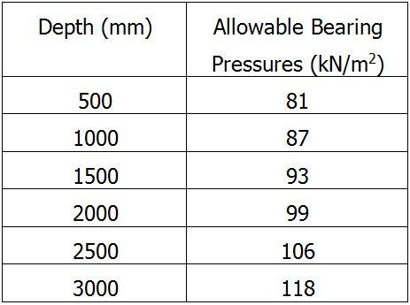
Soil investigation report produced by a geotechnical engineer usually contains the bearing capacity of soil in a site at different depths. The selected depth and bearing capacity used for the foundation design should give an idea of the minimum depth of the foundation. A typical example is shown in the table below;

typical foundation depth from soil test report

From the table above, if a bearing capacity of 87 kPa has been used for the foundation design, the minimum depth of the foundation should be 1000 mm.

Aside from bearing capacity considerations, it is very important to take the depth of foundations beyond the loose or disturbed topsoil, or soil liable to erosion by wind or flood. When a foundation is founded very close to the ground surface, erosion can lead to loss of bearing capacity no matter how strong the strata is in shear resistance.

When the conditions above are met, the major objective should then be to avoid too great a depth to the foundation level. Depending on the nature of the soil, when the excavation of the trench exceeds 1500 mm, supports may be required to keep the sides from caving in. This can cause a lot of disruption to the foundation construction and subsequently add to the cost of the foundation.

Where possible or applicable, the base of a shallow foundation should be kept above the groundwater level in order to avoid the costs of groundwater control and possible instability of the soil due to the seepage of water into the bottom of the excavation. According to Tomlinson et al (1989), it is usually more economical to adopt wide foundations at a comparatively low bearing pressure, or even to adopt the alternative of piled foundations, than to excavate below groundwater level in a water-bearing gravel, sand or silt.

Apart from the considerations of allowable bearing capacity, it is important to extend shallow foundations in clays beyond the soil stratum that is subject to the influences of ground movement caused by swelling and shrinkage, vegetation, frost action, and other effects. Consideration should be given to the stability of shallow foundations on stepped or sloping ground.

The anticipated loading on a foundation can also influence the depth of the foundation. Foundations subjected to high lateral loads and overturning moment should be founded at greater depths where the depth of the foundation and surcharge can improve the factor of safety against overturning and sliding.

Rankine’s formula can be used to estimate the depth of a shallow foundation. However, the answer gotten from the formula is rarely used because of its lack of practical significance. Rankine’s formula for the depth of a shallow foundation is given by;

Df = (qa/Ƴ) × [(1 – sinØ)/(1 + sinØ)]2

Where;
qa = allowable bearing capacity
Ƴ = unit weight of soil
Ø = angle of repose or shearing resistance of soil

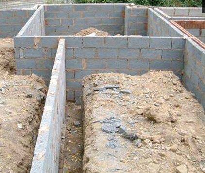
depth of foundation strip
Typical depth of strip foundation

For pad and strip foundations, it is usual to provide a minimum depth of 500 mm as a safeguard against minor soil erosion, the burrowing of insects or animals, heave, and minor local excavations and soil cultivation. It is important to note that this minimum depth is inadequate for foundations on shrinkable clays where swelling and shrinkage of the soil due to seasonal moisture changes may cause appreciable movements of foundations.

A depth of 900 mm to 1000 m is regarded as a minimum at which some seasonal movement will occur but is unlikely to be of a magnitude sufficient to cause damage to the superstructure or ordinary building finishes.

For most duplexes constructed in Nigeria where the bearing capacity of the soil is greater than 100 kN/m2 at shallow depths, a depth of 900 mm to 1200 mm is usually adequate for separate column bases.

References
Tomlinson M. J. (1989): “Foundations Design” in Civil Engineer’s Reference (L. S. Blake eds). Butterworth-Heinemann 1989


Bentley Systems Launches Bentley Education Program

Bentley Systems has announced the launch of Bentley Education program that will provide full access to learning licenses of more than 40 of Bentley’s most popular applications used by infrastructure professionals worldwide. The program offers full access to learning licenses of over 40 of Bentley’s most popular applications used by infrastructure professionals around the globe, including ContextCapture, MicroStation, OpenRoads Designer, STAAD.Pro, and SYNCHRO. The portal can be accessed here.

The Bentley Education program uses a role-based learning approach, allowing future infrastructure professionals to focus on specific capabilities needed for specific professions. Students can go beyond mere product proficiency and develop a comprehensive understanding of the skill sets required to excel in various roles in infrastructure engineering.

Currently, the Bentley Education program is only available in the United Kingdom, Australia, Singapore, Ireland, and Lithuania, with plans to expand to the United States, Canada, Mexico, Latin America, and India by mid-summer. The students/educators or institutes from other countries can navigate to STUDENTserver to use their unique school code provided by their faculty/institute lab administrator for a complimentary software download.

Bentley education program

The Bentley Education portal aims to bridge the gaps in classroom teaching, innovative technology, and best practices learned from real-world projects. Bentley is also asking students from all over the world to come forward with their ideas that improve quality of life and submit those for Future Infrastructure Star Challenge 2021. With infrastructure going digital, the program will help students sharpen their digital design skills and enhance their chances to grab opportunities as AEC professionals.

“With many nations and institutions committing to infrastructure and digital education initiatives as top priorities for a post-pandemic world, we are excited to launch this much-requested and responsive program now,” said Katriona Lord-Levins, Chief Success Officer, Bentley Systems. “We want to inspire and encourage students to learn about infrastructure engineering as a possible career path, and to introduce these young minds to the vast opportunities that lie ahead, with infrastructure going digital.”

Vinayak Trivedi, vice president of Bentley Education, said, “We want to make the Bentley Education portal the place where students can go to learn about and become inspired to make infrastructure engineering their career choice. The goal of the program is to help students who are passionate about infrastructure to get a jump-start on a fulfilling career. The Future Infrastructure Star Challenge 2021 provides an opportunity for them to be creative and innovative in project designs for improving the quality of life and positively changing the world.”

Structville Webinar on the Design of Raft and Pile Foundation

Structville Integrated Services Limited is pleased to announce the second edition of the webinar on the ‘Design of Raft and Pile Foundation’. The details are as follows;

Topic: Structural Analysis and Design of Raft and Pile Foundation
Date: Saturday, 5th of June, 2020
Time: 07:00 pm – 09:00 pm (WAT)
Facilitator: Engr. Ubani Obinna (MNSE, R.Engr)

To register for the event click HERE

webinar foundation design

Features:
(1) Theories and philosophies in the design of shallow and deep foundations
(2) Practical design of pile foundations and pile caps using real-life data
(3) Rigid and flexible approach to the design of raft foundation
(4) Structural design of raft foundation
(5) Full design material (mini textbook) with detailed drawings covering the above topics

To register for the event, click HERE

Use of Lightweight Concrete in RC Design

According to EN 1992-1-1:2004, lightweight concrete is concrete having a closed structure and a density of not more than 2200 kg/m3 consisting of or containing a proportion of artificial or natural lightweight aggregates having a particle density of less than 2000 kg/m3. By having a closed structure, the implication is that the concrete must not be aerated either autoclaved or cured for the requirements stated to apply.

The requirements for normal-weight concrete are generally applicable to lightweight concrete unless specifically varied as described in Chapter 11 of EN 1992-1-1:2004. In general, where strength values originating from Table 3.1 of EC2 are used in Expressions, those values have to be replaced by the corresponding values for lightweight concrete, given in Table 11.3.1 OF EC 2.

Lightweight concrete offers the advantage of considerably reducing the dead load of a structure. According to ASTM 331-05, structural lightweight concrete should not have 28 days compressive strength of less than 17 MPa. Structural lightweight concrete can be applied in;
  • Floors in steel frame buildings (lightweight concrete on fire-rated steel deck assemblies)
  • Concrete frame buildings & parking structures (all types, including post-tensioned floor systems)
  • Bridge decks, piers & AASHTO girders
  • Specified density concrete, etc

To manufacture lightweight concrete, natural or artificial lightweight aggregates could be used (to form a closed structure). Alternatively, the concrete could be aerated or produced with no fines (open structure).

The main natural lightweight aggregates used for production of concrete are;

1. Diatomite
2. Pumice
3. Scoria
4. Volcanic cinders
5. Tuff

Artificial lightweight aggregates can be manufactured by heating raw materials such as shales, clay, and pellets in a kiln at a temperature of about 1200 ℃. Alternatively, molten blast furnace slag or clinker aggregates can be used.

The following symbols are used specially for lightweight concrete:

LC the strength classes of lightweight aggregate concrete are preceded by the symbol LC
ηE is a conversion factor for calculating the modulus of elasticity
η1 is a coefficient for determining tensile strength
η2 is a coefficient for determining creep coefficient
η3 is a coefficient for determining drying shrinkage
ρ is the oven-dry density of lightweight aggregate concrete in kg/m3
For the mechanical properties an additional subscript l (lightweight) is used.

Density Classes

Six density classes are identified for lightweight concrete in EN 206-1. This is reproduced in the table below. The table gives corresponding densities for plain and reinforced concrete with normal percentages of reinforcement which may be used for design purposes in calculating self-weight or imposed permanent loading. Alternatively, the density may be specified as a target value during mix design.

Density class1.01.21.41.61.82.0
Range of density801 – 10001001 – 12001201 – 14001401 – 16001601 – 1800180- 2000
Nominal design density (kg/m3): Plain concrete105012501450165018502050
Nominal design density (kg/m3): Reinforced concrete115013501550175019502150

Many properties of lightweight concrete are related to its density ρ. The coefficient;

η1 = 0.4 + 0.6ρ/2200

is used to modify the relevant property of normal-weight concrete. In this expression, ρ refers to the upper limit of the density for the relevant density class in accordance with the table above.
An estimate of the mean values of the secant modulus Elcm for lightweight concrete may be obtained by multiplying the values in Table 3.1 of EC2, for normal density concrete, by the following coefficient:

ηE = (ρ/2200)2

The strength classes and properties associated with lightweight concrete are shown in the Table below;

Strength class of lightweight concrete

Design compressive strength

The value of the design compressive strength is;
flcd = αlccflckc

The recommended value in the code for αlcc is 0.85. The UK National Annex proposes to adopt the same value.

Similarly, the value of the design tensile strength is
flctd = αlctflctkc
with αlct = 0.85.

Lateral Buckling of Slender RC Beams

Just like columns, beams can undergo lateral buckling instability when it is slender. Slenderness in beams occurs when the width of the beam is too narrow compared to its span or depth. However, this is usually a rare occurence in construction, therefore, simple checks are usually sufficient to check that lateral buckling problem will not occur in beams.

According to clause 5.9 of EN 1992-1-1:2004, a beam will be safe against lateral buckling provided that;

For persistent situations: l0t/b ≤ 50/(h/b)1/3 and h/b ≤ 2.5
For transient situations: l0t/b ≤ 70/(h/b)1/3 and h/b ≤ 3.5

where:
l0t is the distance between torsional restraints
h is the total depth of beam in central part of l0t
b is the width of compression flange

According to EC2, where buckling instability is to be considered in beams, a lateral deflection of l/300 should be assumed as a geometric imperfection in the verification of beams in unbraced conditions, with l = total length of the beam. In finished structures, bracing from connected members may be taken into account. Furthermore, torsion associated with lateral instability should be taken into account in the design of supporting structures.

No indication is given in EN 1992-1-1 as to how a further check should be formulated, should this be necessary. However, a more detailed analysis is given clause 6.7.3.3.4 of the CEB-FIP 1990 Model Code. The method given in the publication has similarities with the nominal curvature method (for analysis of slender columns) in that it postulates an ultimate deflected shape and then ensures that the critical section can withstand the resulting internal actions.

edge beam with parapet
Fig 1: Cross-section of edge beam with parapet

According to Beeby and Narayanan (2009), a problem which occasionally occurs in practice with slender beams is where, for example, an edge beam is designed with a thin parapet cast monolithically as sketched in Fig. 1. Such a beam would normally be designed ignoring the effect of the upstand parapet; however, rigorous interpretation of rules such as those in EN 1992-1-1 would imply that such a member cannot be used because of the slenderness of the parapet. It must, in such circumstances be satisfactory to state that if the beam is adequately safe without the parapet, then the addition of the parapet cannot make it less safe.

References
Beeby A. W. and R. S. Narayanan R. S. (2009): Designers’ Guide to Eurocode 2: Design of Concrete Structures. Thomas Telford Publishing, London