8.7 C
New York
Saturday, September 21, 2024
Home Blog Page 53

Structural Design of Swimming Pools and Underground Water Tanks

I spent a large part of the last few months developing the contents of this booklet on ‘Structural Design of Swimming Pools and Underground Water Tanks (According to the Eurocodes)’. Water is necessary for survival of mankind, but in one way or another, water is relatively scarce. We all know that rain does not fall continuously, and for water to be available for usage in homes, it will have to be fetched/pumped from the stream, or harvested during rainfall, or dug up from the ground. As a result, survival instincts made man to create different means of storing water in order to face the periods of scarcity.

One of the alternatives of storing water is the use of reinforced concrete structures which may be buried under the ground, supported on the ground surface, or elevated above the ground surface. Civil engineers have been at the forefront of designing these infrastructures in order to meet accepted performance criteria. One of the profound requirements of water tanks is water tightness, which can be related to the serviceability limit state requirement of cracking, amongst other factors.

IMG 20181115 WA0002

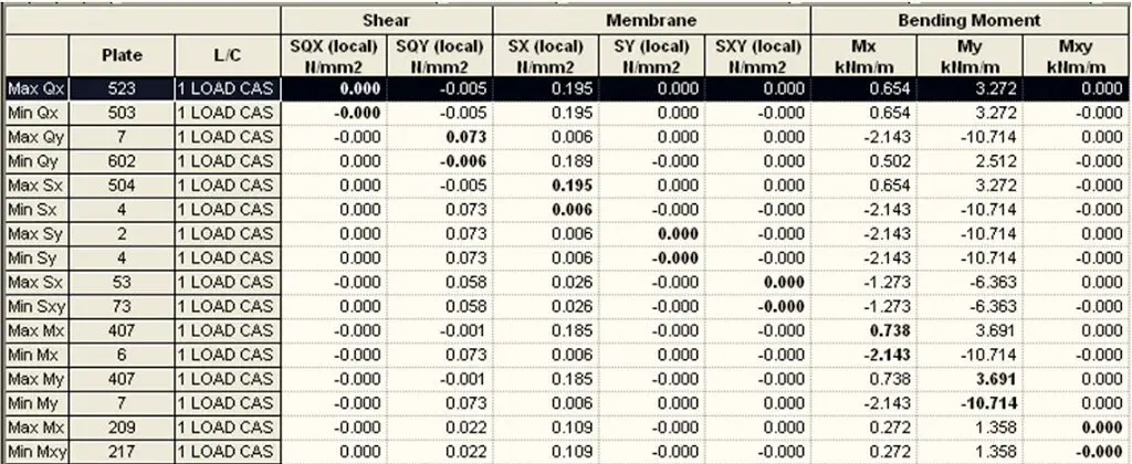
The publication highlighted above focuses on the use of reinforced concrete for construction of underground water tanks and swimming pools. All the factors usually considered in the design of underground water retaining structures such as geotechnical analysis, modelling, loading, structural analysis, and structural design were all presented in an objective manner to the reader. Also, the use of Staad Pro Software was explored in detail on how it can be used to model and analyse tanks and swimming pools.

I am going to use the screenshots below to show you some of the contents, with hope that you will find it interesting. The images are arranged in no specific order.

tension%2B1
Trapezoidal%2BLoads
When%2BModelled%2Bon%2BStaad%2BPro
earth%2Bpressure
Autogenous%2BShrinkage
Long%2BTerm%2BRestraint%2BCracking
swimming%2Bpool
pool%2Bhall%2BGA
3D%2BRENDERING
DIVISION%2BINTO%2BZONES
POOL%2BEARTH%2BPRESSURE
bmds
BASE%2BPRESSURE%2BDISTRIBUTION
calculation
vbn
Autogenous%2BShrinkage
TEMPERATURE%2BDIFFERENCE
POOL%2BTEMPERATURE
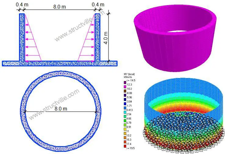
CYLINDRICAL%2BTANK
BRT
6778
FORMWORK
GROUND%2BBEAM
CONSTRUCTION%2BJOINTS

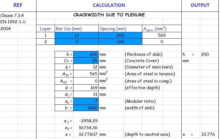
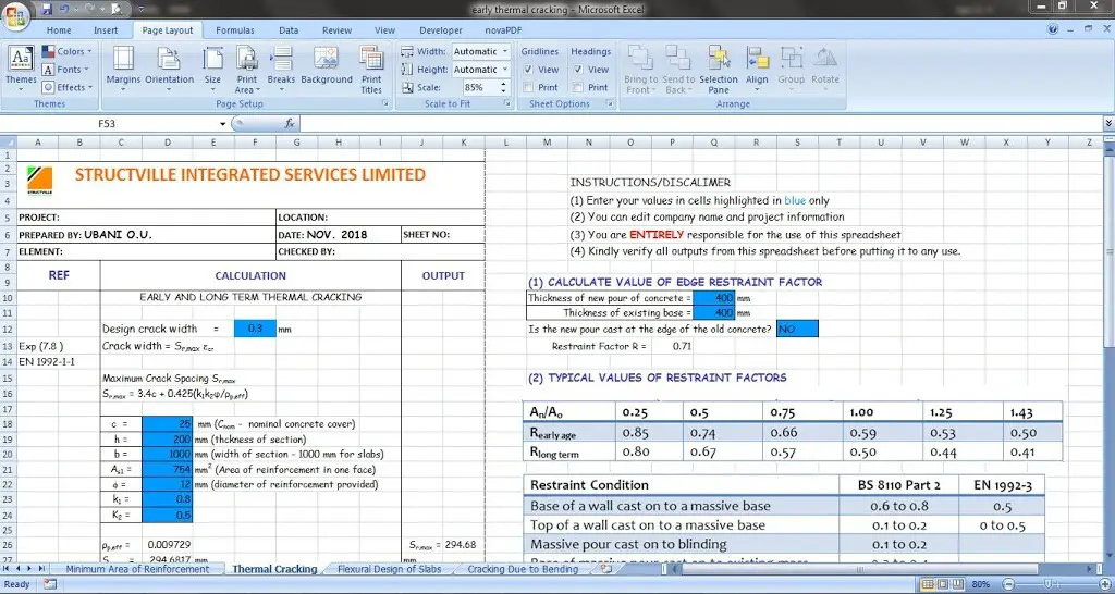
The publication also paid serious attention to how water tightness can achieved on site through careful and standard construction practices. In addition to this 167 pages booklet, I also developed excel spreadsheets that can help make calculation of crackwidths faster, and Staad Pro video tutorials, peradventure you want to master the use of the software. Kindly see screenshot below;

SPREADSHEET

For this reason, there are three different packages that can be purchased to match different levels of interest in the content.

For this reason, there are three different packages that can be purchased to match different levels of interest in the content.
 
PACKAGE 1 (STANDARD)        COST: NGN 3,000
(1) 167 pages booklet on Structural Analysis of Swimming Pools and Underground Water Tanks (in PDF)
 
PACKAGE 2 (ADVANCED)       COST: NGN 4,500
(1) 167 pages booklet on Structural Analysis of Swimming Pools and Underground Water Tanks (in PDF)
(2) Staad Pro Video Tutorial on Modelling and Analysis of Underground Water Tanks
 
PACKAGE 3 (SOPHISTICATED)    COST: NGN 6,000
(1) 167 pages booklet on Structural Analysis of Swimming Pools and Underground Water Tanks (in PDF)
(2) Staad Pro Video Tutorial on Modelling and Analysis of Underground Water Tanks
(3) MS Excel Spreadsheet for design of slabs, and calculation of crackwidths
 
All purchases will be delivered via mail within 24 hours of purchase.

To purchase any of the packages, click HERE

 
Thank you, and God bless you.
 
For more information;
Call: +2348060307054
WhatsApp: +2347053638996
E-mail: rankiesubani@gmail.com
 

How will you describe this system of forces?

What is the best description that you will give to this system of forces?


system%2Bof%2Bforces%2B2

(a) Coplanar parallel system of concurrent forces
(b) Non-coplanar parallel system of non-concurrent forces
(c) Coplanar non-parallel system of concurrent forces
(d) Non-coplanar non-parallel system of non-concurrent forces

E-mail: info@structville.com
WhatsApp: +2347053638996

Are you looking for where you can make free downloads of publications? Visit Structville Research for all your free downloads.

STRUCTVILLE REINFORCED CONCRETE DESIGN MANUAL
We have this very affordable design manual available…

final%2Bfront%2Bcover

Do you want to preview the book, click PREVIEW
To download full textbook, click HERE

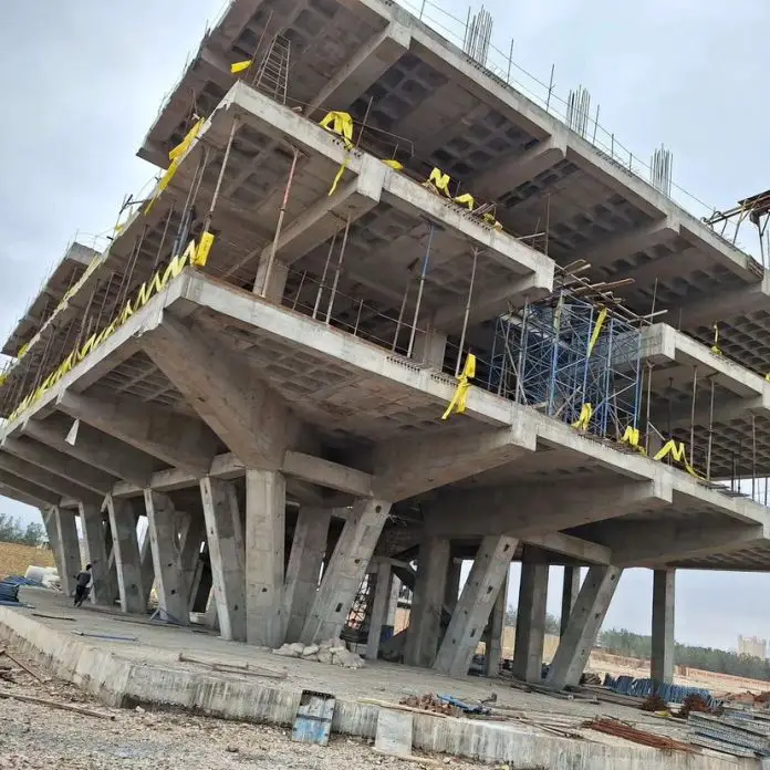
Is This Ultimate or Serviceability Limit State Failure?

Kindly look at the image carefully, and lend your professional opinion if the failure of the building will be categorized under ultimate or serviceability limit state. By posting and discussing your opinion on the comment section, I am very certain that knowledge and deeper understanding of this topic will be enhanced.

Thank you very much.

IMG 20180420 162721


E-mail: info@structville.com
WhatsApp: +2347053638996

Are you looking for where you can make free downloads of publications? Visit Structville Research for all your free downloads.

STRUCTVILLE REINFORCED CONCRETE DESIGN MANUAL
We have this very affordable design manual available…

final%2Bfront%2Bcover

Do you want to preview the book, click PREVIEW
To download full textbook, click HERE

Aspects of Modelling of Shear Walls

Shear walls are structural elements usually employed in tall buildings to assist in resisting lateral loads. Shear walls can be solid or pierced (coupled), depending on their location in the building. In the design of  tall buildings, structural engineers normally throw the entire lateral load (say wind action) to the shear walls, which means that the columns will not be relied on for lateral stability. In a more practical scenario however, the shear walls and columns interact in resisting lateral loads, which can be taken into account.

[the_ad id=”498″]

In this post, we are going to review how shear walls can be modelled on Staad Pro software and consider the various accuracy levels with each method.

Let us consider the shear wall shown below;

shear%2Bwall%2Bmodel

Thickness of the wall = 250 mm
The wall is subjected to a lateral load of 300 kN at the top.

Model 1: Equivalent frame model
In this model, we represent the shear wall as an equivalent frame with representative stiffness for the various elements.

shear%2Bwall%2Bequivalent%2Bframe%2Bmodel

On modelling this Staad Pro, we obtained the result shown below;

deflected%2Bprofile

The maximum horizontal deflection was obtained to be 158.376 mm.


Model 2: Plate modelling (Finite Element Mesh)

In this model, the shear wall is modelled as a full plate with approximate mesh size of (4 x 4) per square metre. The deflection due to the lateral load is given below;

modelling%2Bas%2Bplate

The maximum horizontal deflection was obtained to be 156.588 mm.

It is important also to compare the deflection obtained by considering different mesh sizes in order to compare the accuracy of utilizing the equivalent frame model. Thank you for visiting Structville today, and God bless.


Buckling of Columns

When structural members are subjected to compressive forces, the members may fail before the compressive resistance (A.fy) is reached. This premature failure is usually caused by secondary bending effects such as imperfections, the eccentricity of loading, asymmetry of the cross-section etc. In such cases, the failure mode is normally buckling.

The buckling of columns is usually associated with a sudden large displacement (bending) on the column following a slight increase or modification of an existing compressive load. The load at which the buckling of columns occur is usually less than the compressive resistance of the column, and it is mainly influenced by the length, cross-section, and boundary conditions of the column.

This is unlike when the member is subjected to tensile forces, where the member will generally fail when the stress in the cross-section exceeds the ultimate strength of the material. Members subjected to tensile forces are inherently stable.

In essence, for very short columns or members subjected to tensile forces, the stress is proportional to the load, and the failure load is equal to the yield stress times the area of the cross-section (A.fy). Commonly, compression members can be classified as short, intermediate, or slender depending on their slenderness ratio. Short elements will fail by crushing, slender elements will fail by excessive lateral deflection, and intermediate elements will fail by the combination of both.

Types of Buckling

  1. Flexural buckling (Euler)
  2. Lateral-torsional buckling
  3. Torsional buckling
  4. Snap-through buckling
  5. Local plate buckling

In this article, we are going to focus on flexural buckling.

In the year 1757, Leonhard Euler developed a theoretical basis for the analysis of premature failure due to buckling. The theory was based on the differential equation of elastic bending of a pin-ended column, which related the applied bending moment to the curvature along the length of the column.

For a pin-ended column, the critical Euler buckling load (K = 1.0) is given by;

PE = Kπ2EI/L2

buckling of columns

Note that L in this case is the effective buckling length which depends on the buckling length between the pinned supports or the points of contraflexure for members with other boundary conditions.

Subsequently, the Perry-Robertson formula was developed to take into account the deficiencies of the Euler method. The formula evolved from the assumption that all practical imperfections could be represented by a hypothetical initial curvature of the column. In the UK, the Perry-Robertson formula was modified and is referred to in BS 5950 as the Perry-Strut formula. As a matter of fact, it also forms the basis of flexural buckling in BS EN 1993 (Eurocode 3).

Worked Example on the Buckling of Columns

In the example below, we are going to show how the failure load of a column changes with an increase in effective length due to the phenomenon of buckling.

Let us investigate the load-carrying capacity of UC 305 x 305 x 158 according to EC3. We will consider the ends of the column to be pinned, and we will start with an initial length of 1.0 m.

Properties of UC 305 × 305 × 158

D = 327.1 mm; B = 311.2 mm; tf = 25mm; tw = 15.8mm; r = 15.2mm; d = 246.7mm, b/tf = 6.22; d/tw = 15.6; Izz = 38800 cm4; Iyy = 12600 cm4; iy-y = 13.9cm; iz-z = 7.9 cm, A = 201 cm2

New%2BPicture%2B%25281%2529

Thickness of flange tf = 25mm.
Since tf  > 16mm, Design yield strength fy = 265 N/mm2 (Table 3.1 EC3)

Section classification

ε = √(235/fy ) = √(235/265) = 0.942

We can calculate the outstand of the flange (flange under compression)
C = (b – tw – 2r) / (2 ) = (327.1 – 15.8 -2(15.2)) / (2 ) = 140.45mm.
We can then verify that C/tf = 140.45/25 = 5.618
5.618 < 9ε i.e. 5.618 < 8.478.

Therefore the flange is class 1 plastic

Web (Internal compression)
d/tw = 15.6 < 33ε so that 15.6 < 31.088. Therefore the web is also class 1 plastic

Resistance of the member to uniform compression (clause 6.2.4)
NC,Rd = (A.Fy)/γmo = (201 × 102 × 265) / 1.0 = 5326500 N = 5326.5 kN

Buckling resistance of member (clause 6.3.1)

Since the member is pinned at both ends, the critical buckling length is the same for all axis Lcr = 1000 mm

Slenderness ratio ¯λ = Lcr/(ri λ1)
λ1 = 93.9ε = 93.9 × 0.942 = 88.454

In the major axis
(¯λy ) = 1000/(139 × 88.454) = 0.081
In the minor axis
(¯λz ) = 1000/(79 × 88.454) = 0.143

Check h/b ratio = 327.1/311.2 = 1.0510 < 1.2, and tf < 100 mm (Table 6.2 EN 1993-1-1:2005)

Therefore buckling curve b is appropriate for the y-y axis, and buckling curve c for the z-z axis. The imperfection factor for buckling curve b, α = 0.34 and curve c, α = 0.49 (Table 6.1)

Φ = 0.5 [1 + α(¯λ – 0.2) + ¯λ2]

Φz = 0.5 [1 + 0.49 (0.143 – 0.2) + 0.1432 ] = 0.496
Φy = 0.5 [1 + 0.34 (0.081 – 0.2) + 0.0812 ] = 0.483

X = 1/(Φ  + √(Φ2 -¯λ2))
Xz = 1/( 0.496 + √(0.4962 – 0.1432)) = 1.02 > 1 (cannot be greater than 1, so take 1.0)
Xy = 1/( 0.483 + √(0.4832 – 0.0812)) = 1.04 > 1 (cannot be greater than 1, so take 1.0)

Therefore Nb,Rd = (Xz A.Fy)/γm1 = (1.0 × 201 × 102 × 265) / (1.0 ) = 5326500 N = 5326.5 kN

Nb,Rd = NC,Rd = 5326.5 kN

This tells us that the column is short and that at a length of 1.0 m, the column will fail by crushing. Buckling is not a significant mode of failure. If we incrementally increase the length of the column by 1.0 m and follow the steps described above, we will arrive at the following results;

Column length (m)Failure Load (kN)
15326
23090
34700
44270
53810
63330

The graph of the relationship is given below;

image 22

Therefore, the load-carrying capacity of compression members reduces with an increase in length. When the height of the pin-ended column was increased from 1m to 6m, a reduction of about 37% was observed in the buckling load. In the design of axially loaded members such as trusses, it is, therefore, advisable to design the members in such a way that the longer members are in tension and the shorter members are in compression.

Thank you for visiting Structville today, and God bless.


Structural Design of Cantilever Slabs

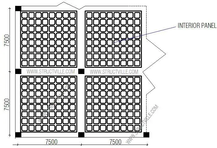
Cantilever slabs are common features in residential and commercial buildings due to the need to have bigger spaces on upper floors. To achieve this, architects normally extend the slab beyond the ground floor building line, thereby forming a cantilever. Cantilever slabs in reinforced concrete buildings are usually characterised by a reinforced concrete slab projecting from the face of the wall and having a back span that extends into the interior panels of the building.

The design of reinforced concrete cantilever slab is usually governed by serviceability limit state requirements. Typically, the design involves the provision of adequate concrete thickness and reinforcement to prevent excessive deflection and vibration.

During the detailing of reinforced concrete cantilever slabs, the main reinforcements are provided at the top and they extend into the back span by at least 1.5 times the length of the cantilever or 0.3 times the length of the back span, whichever is greater. Furthermore, it is important to provide at least 50% of the reinforcement provided at the top, and at the bottom.

In this article, we are going to show how we can analyse and design cantilever slabs subjected to floor load and block wall load according to the requirements of EN 1992-1-1:2004 (Eurocode 2).

cantilever slab design
Cantilever slab supporting block wall load


Worked Example – Design of Cantilever Slabs

A cantilever slab 200 mm thick is 1.715m long, and it is supporting a blockwork load at 1.0m from the fixed end. Design the slab using the data given below;

Purpose of building – Residential
fck = 25 Mpa
fyk = 460 Mpa
Concrete cover = 25 mm
Height of block wall = 2.75 m
Unit weight of concrete = 25 kN/m3
Unit weight of block with renderings = 3.75 kN/m2

Load Analysis 

Self weight of slab = (25 × 0.2) = 5 kN/m2
Finishes (assume) = 1.2 kN/m2
Partition allowance = 1.0 kN/m2
Total characteristic permanent action (pressure load) gk  = 7.2 kN/m2

Permanent action from wall Gk = 3.75  × 2.75 = 10.3125 kN/m

Variable action on slab qk = 1.5 kN/m2

At ultimate limit state;
n = 1.35gk + 1.5qk
n = 1.35(7.2) + 1.5(1.5) = 11.97 kN/m2

Ultimate load from wall = 1.35 x 10.3125 =  13.92 kN/m

analysis%2Bof%2Bcantilever%2Bslab

Design Forces

MEd = (13.92 × 1) + (11.97 × 1.7152)/2 = 31.523 kNm
VEd = (13.92) + (11.97 × 1.715) = 34.45 kN

Flexural design

MEd  = 31.523 kNm
Effective depth (d) = h – Cnom – ϕ/2 – ϕlinks
Assuming ϕ12 mm bars will be employed for the main bars
d = 200 – 25 – 6 = 169 mm

k = MEd/(fckbd2) = (31.523 × 10⁶)/(25 × 1000 × 1692) = 0.044

Since k < 0.167, no compression reinforcement required
z = d[0.5+ √(0.25 – 0.882K) ]
z = d[0.5+ √(0.25 – 0.882(0.044))] = 0.95d

As1 = MEd/(0.87fyk z) = (31.523 × 10⁶)/(0.87 × 460 × 0.95 × 169) = 490 mm2/m
Provide X12@200 c/c  TOP (ASprov = 565 mm2/m)

Check for deflection

ρ = As,prov /bd = 565 / (1000 × 169) = 0.0033
ρ0 = reference reinforcement ratio = 10-3√(fck) = 10-3√(25) = 0.005
Since if ρ ≤ ρ0;

L/d = K [11 + 1.5√(fck) ρ0/ρ + 3.2√(fck) (ρ0 / ρ – 1)(3⁄2)

k = 0.4 (Cantilevers)

L/d = 0.4 [11 + 1.5√(25) × (0.005/0.0033) + 3.2√(25) × [(0.005 / 0.0033) – 1](3⁄2)
L/d = 0.4[11 + 11.363 + 5.9159] = 11.311

βs = (500 Asprov)/(fyk Asreq) = (500 × 565) / (460 × 490) = 1.253

Therefore limiting L/d = 1.253  × 11.311 = 14.172
Actual L/d = 1715/169 = 10.147

Since Actual L/d (10.147) < Limiting L/d (14.172), deflection is satisfactory.

Exercise for Students
(1) Provide distribution bars
(2) Verify the section for shear
(3) Check for cracking
(4) Do the detailing sketches

Thank you for visiting Structville today, and God bless.

How to Calculate the Quantity of Mortar (Sand and Cement) for Laying Blocks

Engineers, site managers, and quantity surveyors are always faced with the challenge of specifying as accurately as possible, the quantity of materials needed to execute a specific item of work. In this article, we are going to explain how you can estimate the quantity of mortar (cement and sand) needed to lay blocks per square metre of wall.

It is well known that we need about 10 blocks to build one square metre of wall.

Simple Proof;
Area of wall = 1 m2
Planar area of one standard block (Nigeria) = 450mm x 225mm = 101250 mm2 = 0.10125 m2
Therefore, the number of blocks required (disregarding mortar) = 1/0.10125 = 9.87 (say 10 blocks)

Now, how do we estimate the quantity of mortar needed to lay the blocks? First of all, let us look at the dimensions of a typical 9 inches block with holes (the most popular block for building in Nigeria).

Typical dimensions for sandcrete blocks

From the image of the sandcrete, we can say that the cross-sectional area of the block that receives horizontal mortar is;

Ab = (0.45 x 0.225) – 2(0.15 x 0.125) = 0.0637 m2

Now, let us assume that the mortar will be 25 mm (1 inch) thick.

The typical arrangement of blocks in a one square metre wall is shown below;

arrangement%2Bof%2Bblocks%2Bin%2Ba%2Bone%2Bsquare%2Bmetre%2Bwall

Therefore, we can estimate the volume of mortar required to build one square metre (1 m2) of wall as follows;

Vertical mortar = 8 x (0.025 x 0.225 x 0.275) = 0.0123 m3
Horizontal mortar = 10 x (0.0637 x 0.025) = 0.0159 m3
Total = 0.0282 m3

Therefore the volume of mortar required to lay one square metre (1 m2) of 9-inch block (with holes) can be taken as 0.03 m3 for all practical purposes.

Cement requirement
The typical mix ratio for mortar (laying of blocks) is 1:6
Quantity of cement required = 1/7 x 1440 kg/m3 = 205.71 kg
Making allowance for shrinkage between fresh and wet concrete = 1.54 x 205.71 = 316.79 kg
Quantity of cement required in bags = 316.79/50 = 6.33 bags/m3 of mortar

Therefore, the quantity of cement required to lay 1m2 of wall = 0.03 × 6.33 = 0.1899 bags
If 0.1899 bags of cement = 10 blocks
Therefore, 1 bag of cement = 52 blocks

Therefore, 1 bag of cement is required to lay 52 blocks using a 1:6 mix ratio of mortar.

Sand
Quantity of sand required = 6/7 x 1600 kg/m3 = 1371.428 kg
Making allowance for shrinkage between fresh and wet concrete = 1.54 x 1371.428 = 2112 kg
Quantity of sand required in tonnes = 2.112 tonnes/m3 of mortar

Therefore, the quantity of sand for mortar required to lay 1m2 of wall = 0.03 × 2.112 = 0.06336 tonnes of sand
If 0.06336 tonnes of sand = 10 blocks
Therefore, 1 tonne of sand = 157 blocks

Therefore, 1 tonne (1000 kg) of sand is required to lay 157 blocks using a 1:6 mix ratio of mortar.

Further Example
To go further, let us assume that we have 150 m2 (about 1500 blocks) of wall and want to estimate the quantity of cement and sand needed to lay the blocks.

The volume of mortar required = 0.03 x 150 = 4.5 m3

For 4.5m3 of mortar;
Provide = 4.5 x 6.33 = 29 bags of cement

For 4.5m3 of mortar;
Provide = 4.5 x 2112 = 9504 kg of sharp sand

Therefore you need about 10 tonnes of sharp sand and 29 bags of cement for laying 150m2 of 9 inches block wall.

Thank you for visiting Structville today, and God bless.


Analysis and Design of Pedestrian Bridge Using Staad Pro

Pedestrian bridges (footbridges) are structures designed to enable human beings cross over obstacles such as busy highways, water bodies, gullies, etc. There are several variations of foot bridges based on structural configuration and materials. Modern footbridges are increasingly becoming elements of street beautification, with a view on sustainability and environmental friendliness. In this post, a simple pedestrian bridge has been modelled on Staad Pro software, and the result of internal stresses due to crowd load on the bridge presented.

Actions on Bridges
The actions on footbridges is explicitly covered in section 5 of EN 1991-2. The load models presented in the code and their representative values (which include dynamic amplification effects), should be used for ultimate and serviceability limit state static calculations. However, adhoc studies are required when vibration assessment based on specific dynamic analysis is necessary.

There are three mutually exclusive envisaged vertical load models for footbridges (5.3.1(2) EN 1991-2:2003);

(1) A uniformly distributed load representing static effect of a dense crowd,
(2) One concentrated load representing the effect of maintenance load,
(3) One or more, mutually exclusive standard vehicles to be taken into account when maintenance or emergency vehicles are expected to cross the footbridge itself (not applicable in this post).

The effect of crowd action on a footbridge is represented by a uniformly distributed load which depends on the loaded length of the footbridge. However, when a road bridge is supporting a footway, a UDL value of 5.0 kN/mis recommended by the code for that section. This value is synonymous with continuous dense crowd action which is given by Load Model 4 of road bridges. However, when there is no such risk of dense crowd action, the load on the pedestrian bridge is given by;

qfk = 2.5 kN/m2 ≤ 120/(L + 30) ≤ 5.0 kN/m2

For local assessment, a concentrated load of 10 kN is is considered to be acting on a square surface of sides 0.1 m. This load is not to be combined with other variable non-traffic load.

For horizontal forces, a horizontal force acts simultaneously with the corresponding vertical load whose characteristic value is equal to 10% of the total load corresponding to the uniformly distributed load. This horizontal force does not coexist with the concentrated load, and acts along the bridge deck axis at the pavement level on square surface of sides 0.1 m. This force is usually sufficient to ensure the horizontal longitudinal stability of the bridge.


However, there are non-traffic actions that are possible on footbridges such as thermal action, wind action, snow action, indirect actions such as support settlement, etc. It is also important to consider accidental actions on the bridge especially vehicle collision on the substructure of the bridge.  For stiff piers, EN 1991-2:2003 recommends a minimum force of 1000 in the direction of vehicle travel or 500 kN in the perpendicular direction. These collision forces are supposed to act at 1.25 m above the level of the ground surface.

N/B: Vehicle collision on the piers is more common on footbridges than highway bridges. Therefore, it is highly recommended that the piers of the footbridge be protected using any reasonable and effective approach. Road restraint system can be installed at a distance from the piers. The deck should be high enough to prevent collision also.

Analysed Example
A pedestrian bridge with the following configuration is shown below;

footbridge%2Bplan%2Bview
fuller%2Bsection
bridge%2Bmodel%2Bsection
stairs%2Bsection


cantilever%2Bstairs
section

With these dimensions shown above, the pedestrian bridge has been modelled on Staad Pro…
For the sake of clarity, the cross-sectional dimensions of the members are as follows;

Main longitudinal girders – 400 x 750 mm
Transverse girders at the supports – 400 x 750 mm
Intermediate transverse girders – 250 x 450mm
All columns – 400 x 400 mm
Thickness of slab – 200 mm

MODELLING%2BOF%2BPED
3D%2BMODEL%2BFULL%2BPEDESTRIAN
footbridge%2Bdesign%2BStaadpro
The self weight of the structure will be calculated automatically by Staad Pro. The pedestrian crowd action has been calculated as;

qfk = 120/(27 + 30) = 2.10 kN/m2 ≤ 2.5 kN/m2

But let us envisage that there is a possibility of continuous dense crowd action (e.g the pedestrian bridge at Ojota, Lagos, or lets say the pedestrian bridge will be located as Oshodi Bus Stop, Lagos). In this case, it is very reasonable to take qfk as 5.0 kN/m2

The total force due to UDL on the bridge can be taken as 5 kN/m2 x 2m  x 27m = 270 kN
Therefore, an equivalent horizontal force that can be applied on the bridge deck is 27 kN

The images below show the internal stresses diagram due to crowd load;

BENDING%2BMOMENT%2BDIAGRAM

The maximum moment at the intermediate supports of the main longitudinal beam due to characteristic crowd load is 62.7 kNm.

The other internal forces diagrams due to crowd load alone are shown below;

SHEAR%2BFORCE%2BDIAGRAM


BM%2BSTAIRS
PLATE%2BMOMENT

So we are going to stop here for now. Remember that you have to consider other load cases and combinations in order to arrive at the design moment.

The modelling, analysis, and drawings you see on this post was produced by Ubani Obinna for Structville Integrated Services. We are creative, we think critically, we research, and we solve problems. You can trust us with yours, so feel free to contact us.

WhatsApp: +2347053638996
E-mail: ubani@structville.com


Bonding of Old and New Concrete

In construction, there always comes a time when there is a need to bond hardened concrete (substrate) with fresh concrete topping/overlay. The aim of this post is to explain how to bond old and fresh concrete successfully. Furthermore, we will review the strength of the interfacial bond between old and new concrete based on laboratory studies.

Proper bonding is very important for adequate performance when the fresh concrete topping is used to overlay an existing hardened concrete. This construction feature is usually found in bridge deck construction, concrete pavements, precast filigree slab, pile caps (in some cases) etc. Proper bonding between the substrate and the topping is not always guaranteed unless simple precautions are taken.

For adequate bonding, it is very important to prepare the surface of the substrate adequately. The preparation of the surface usually involves roughening the surface, and removal of all dirt, oil, grease, and loosened or unbonded portions of the existing concrete.

By implication, the surface of the substrate should be hard, firm, clean, and free from loosened particles. This can be achieved by the use of chipping hammers, wire brushing the surface etc. After this is done, the exposed concrete surface can be cleaned by using pressurised clean water, air, etc. The man hours involved depend on the area of the surface, location, and the ease of cleaning (e.g reinforcement obstruction).

precast%2Bfiligram%2Bslab


After surface preparation, there is usually a need to apply a bonding agent on the surface of the existing concrete in order to facilitate the bonding. Epoxy-based bonding agents are very popular for such operations. It is recommended that a bonding agent is applied prior to casting the fresh concrete.  In essence, the procedure should be ‘wet-to-wet’ as the bonding agent should not be allowed to dry before the fresh concrete topping is placed.

bonding%2Bagent
Hardened Concrete With Bonding Agent Ready for Topping/Overlay

In a research carried out by Vandhiyan and Kathiravan (2017), the compressive strength of monolithic and bonded concrete was compared using 150mm x 150mm cube specimens at 28 days. With an epoxy-based bonding agent, the compressive strength of the bonded concrete was about 5% less than the monolithic strength, while without the bonding agent, the compressive strength was about 28% less than the monolithic compressive strength.

Research has also shown that the moisture condition of the substrate affects the shear bond strength of bonded concrete. Shin and Wan (2010) investigated the interfacial bond strength of old and new concrete considering saturated surface dry (SSD) and air dry conditions. Saturated surface dry is a condition in which the concrete contains moisture that is equal to its potential absorption, without the surface being wet or damp.

At a water/cement ratio of 0.45 (for the topping concrete), the shear bond strength at the interface was about 44% greater when the substrate was at SSD condition than when it was air dry. At a water/cement ratio of 0.6 for the topping layer, an increase in shear bond strength was recorded, but there was a reduction in the compressive strength of the concrete.

So the recommendation in this article is that when casting a topping layer of fresh concrete on old concrete, adhere to the following guidelines;

(1) Prepare the surface properly
(2) Make sure that the substrate is at saturated surface dry condition
(3) Use a bonding agent and follow the manufacturer’s technical recommendation properly.

Thank you for visiting Structville today, and God bless you.

References
Vandhiyan R., Kathiravan M. (2017): Effect Of Bonding Chemical On Bond Strength Between Old And New Concrete. SSRG International Journal of Civil Engineering- (ICRTCETM-2017) – Special Issue – April 2017 ISSN : 2348 – 8352 pp 129-134

H-C. Shin,  Z. Wan (2010): Interfacial shear bond strength between old and new concrete. Fracture Mechanics of Concrete and Concrete Structures – Assessment, Durability, Monitoring and Retrofitting of Concrete Structures- B. H. Oh, et al. (eds) ⓒ 2010 Korea Concrete Institute, Seoul, ISBN 978-89-5708-181-5 pp 1195 – 1200


Meet the Winners of Structville Design Competition

In the month of May, we announced the commencement of Structville Design Competition, where civil engineering students and serving NYSC members from various universities and polytechnics in Nigeria competed for small tokens in the design of reinforced concrete structures. The exercise was aimed at developing the interest of students in Structural Design, and preparing them for excellence in the field of structural engineering. You can view the details of the competition below;


Structville Design Competition for Students

To view the result sheet of the competition, click the link below;

Structville Design Challenge Results

Let us meet the outstanding performers……

1st Position – USMAN UMAR (Ahmadu Bello University, Zaria)

IMG 20180216 221336

Usman Umar is a 500 level student from the Department of Civil Engineering, Faculty of Engineering, Ahmadu Bello University, Zaria, and he’s  an indigene of Ankpa LGA, Kogi State, Nigeria. While speaking to Structville during an interview, Usman dreams of becoming a structural engineer with vast experience in both consultancy and construction field, and he is quite willing to work with any consultancy or construction firm.

On what motivated him to study civil engineering, he said,

I grew up with the curiosity of learning the principles which guide the operations of machines and systems. By the time I was in secondary school I already knew I had to go for studying  an engineering course. Although I almost opted for electrical engineering while preparing for UTME, the awesomeness in the the construction of structures such as bridges and skyscrapers couldn’t let me. So I went for Civil Engineering.

Usman believes that a lot is being taught in Nigerian classrooms, but the technical know-how and the method of teaching adopted by a lecturer determine how much is impacted unto the students. Therefore, he believes that the Nigerian tertiary institutions are doing fairly good, but a lot more should be invested in order to raise the standard higher. 

Usman revealed that he has no definite studying pattern, but makes sure that he takes his courseworks seriously, and by consulting a lot of design textbooks and studying the architectural drawings carefully, he was able to do well in the Structville design competition.

So we all at Structville say a big congratulations to Usman Umar once again.

2nd Position – Ogungbire Adedolapo (Osun State University, Osogbo)


Adedolapo


Ogungbire Adedolapo Mojed, is a final year Civil Engineering student at Osun State University, Osogbo. He hails from Odo-Otin Local Government, Osun state. It has always been his childhood dream to grow up to become a Civil Engineer.

Adedolapo would like to own his own consultancy firm one day, and he believes that much experience will be needed in order to achieve that. He is aspiring to work with experienced Engineers and gain as much relevant experience as he can after graduating from the university. He is currently on the lookout for opportunities for pre-NYSC internship, and will be rounding off his degree programme by September 2018.

On the state of teaching and learning in Nigeria, he is an advocate of more practical approach to learning. According to him;

I believe a more practical approach will be more welcomed for training Civil Engineering students in the country. We should not only be bound to the theoretical examples that we have in textbooks but relate them to practical applications in Nigeria.

Adedolapo is curious to learn new things, and he flying high academically in his school. He said there was no special approach to the design competition on his own part. As an individual, he prefers self-studying and understanding the concepts behind what he is studying. That has helped him come a long way.

Congratulations Adedolapo once again.

3rd Position – Olajide Bukoye (Federal Polytechnic Offa, Kwara State)


IMG 20150531 171339 edit


Bukoye, Issa Abiola is a graduate of Federal Polytechnic, Offa in Kwara State. He is currently observing his mandatory National Service in Oyo state. Bukoye boasts of some years of field experience field experience and and have executed some practical designs in his career so far.

According to him,

Civil Engineering has always being my childhood dream not because it’s a lucrative job but because I want to make a difference. 70% of science students in high school wants to be a Doctor, but I’ve never for once dreamt of that because I’m good with numbers and I don’t want to waste the talent. I guess Civil Engineering has always been in my blood.
Bukoye believes that the quality of teaching in Nigeria is far from standard, but he is optimistic and hopeful of positive turnarounds. If he were to make changes in Nigeria, he would focus on the education system.

Bukoye is a goal driven person, and loves to take on any challenges because he believes that every challenge is an experience and once done and dusted, it goes to one’s achievements archive. After his NYSC program, he plans to secure a job and as well go back to school not just for the certificates but to learn more in the field of civil/structural engineering. 
 
We say a very big congratulations to you Bukoye.