8.7 C
New York
Sunday, November 24, 2024
Home Blog Page 52

Advise on the Stability of this Structure

Screenshot 20190421 181440 1 1 1

As a structural engineer, advise the client/architect on the stability of the structure, distinguishing between transient and permanent situation.

Height – 11.28 m
Length – 20.00 m


Screenshot 20190421 182059 1 1

Screenshot 20190421 182125 1

Note: This is an existing observatory structure in Tielt-Winge Belgium. Report has it that it was recently vandalised and is looking to be rebuilt…

Comparative Analysis of Cylindrical Water Tanks

Water tanks are usually rectangular or cylindrical in shape. Cylindrical tanks are normally used for surface or elevated water tanks, while rectangular tanks can be used for underground, surface, or elevated water tank construction. The aim of this article is to compare the analysis of cylindrical water tanks subjected to hydrostatic load using the classical method and finite element analysis.

Some researchers have tried to compare the structural performance of cylindrical and rectangular water tanks under the same conditions such as volume, height above the ground, or aspect ratio. A study carried out in the year 2017 showed that circular water tanks require lesser materials than rectangular water tanks. However, some of the challenges in the construction of cylindrical tanks are increased cost of setting out, formwork preparation/installation, reinforcement installation, and general increased labour cost when compared with a rectangular tank.

Cylindrical tanks are subjected to radial pressure from the stored water, and/or from the retained earth when they are buried under the ground. Just like rectangular water tanks, the analysis of cylindrical water tanks can be easily done with the use of coefficients picked from tables (see Table 1). The values of the coefficients are usually based on the support condition of the wall relative to the base.

Analysis of cylindrical water tanks
Fig 1: Elevated circular water tank

The internal stresses normally analysed for in circular tanks are;

  • Circumferential tension (hoop tension)
  • Radial shears
  • Vertical moments

If the walls of the tank are supported on the base in such a way that no radial movement can occur, radial shear and vertical bending result, and the circumferential tension are zero at the bottom of the wall. This is usually referred to as the fixed joint condition and has been considered in this article.

Analysis of Cylindrical Water Tanks – Worked Example

Determine the maximum service values for circumferential (hoop) tension, vertical moment and radial shear in the wall of a cylindrical tank that is free at the top edge and fixed at the bottom. The wall is 400 mm thick, the tank is 4 m deep, the diameter is 8 m, and the water level is taken to the top of the wall.

Hydrostatic pressure at the base of the tank (n) = 10 kN/m3 × 4 m = 40 kN/m2
From Table 1;
lz2/Dh = 42/(8 × 0.4) = 5
Maximum hoop tension (t) = αtnr = 0.477 × 40 × 4 = 76.32 kN/m

Table 1: Coefficients for Analysis of Cylindrical Tanks Fixed at the Base (Reynolds and Steedman, 2008)

Table 2Bfor 2BAnalysis 2Bof 2BCylindrical 2BTanks

Maximum vertical negative moment (outside face) = αmnlz2 = 0.0059 × 40 × 42 = 3.776 kNm/m
Maximum vertical positive moment (inside face) = αmnlz2 = 0.0222 × 40 × 42 = 14.208 kNm/m
Radial shear V = αvnlz = 0.213 × 40 × 4 = 34.08 kN/m

When analysed on Staad Pro as a concrete cylindrical tank with a Poisson ratio of 0.2, fixed at the bottom, and subjected to a hydrostatic pressure of 40 kN/m2 the following results were obtained;

Modelling 2Bof 2Btank 2Bon 2BStaad 2BPro 2BFEM
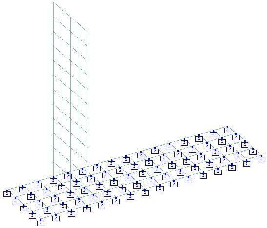
Fig 2: Finite Element Meshing of Cylindrical Tank on Staad Pro
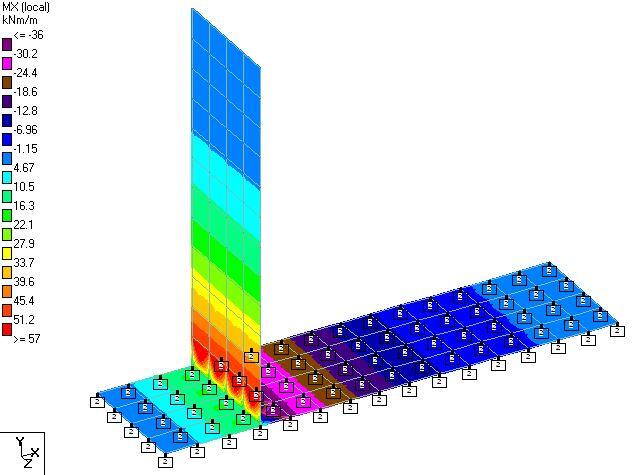
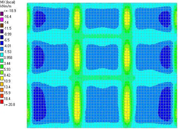
Mx
Fig 3: Horizontal Moment on the Tank Walls
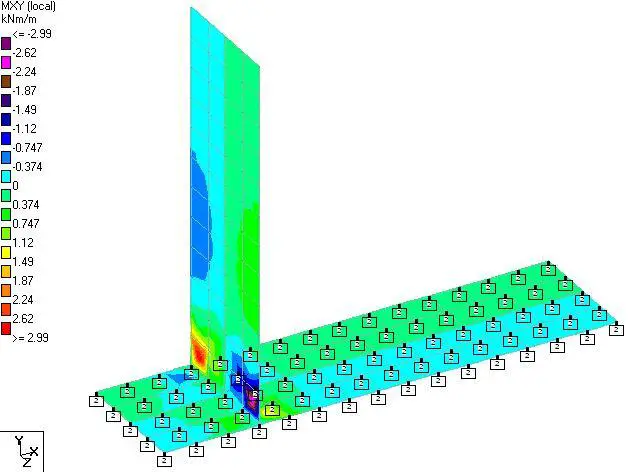
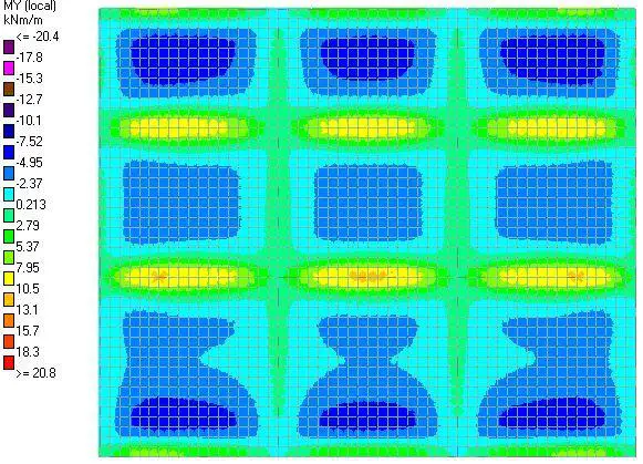
My
Fig 4: Vertical Bending Moment on the Tank Walls

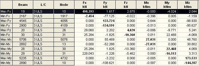
The summary of the finite element analysis results from Staad Pro is shown in Table .

Table 2: Summary of the finite element analysis results from Staad Pro

table 2Bof 2Bresults 1

Maximum vertical bending moment = 10.714 kNm/m
Maximum vertical shear stress = 0.073 N/mm2 = 29.2 kN/m
Maximum hoop stress (membrane) = 0.195 N/mm2 = 78 kN/m
Let us compare the results from Staad Pro with results from the use of coefficients (see Table 3).

Table 3: Comparison of analysis result using classical method and finite element analysis

Comparison 2BTable 1

Thank you for visiting Structville today and God bless you. If you have some time, you take a look at our QUIZ and evaluate your performance.

Solution to 25 Top Civil Engineering Questions

Civil 1


Examiner: Structville Integrated Services

(1) Mechanics of deformable bodies is usually studied under?
(A) Statics
(B) Strength of Materials
(C) Dynamics

Answer is (B): Strength of Materials is deformable bodies mechanics, while statics is rigid body mechanics. Dynamics is the mechanics of bodies in motion.

(2) Which structural model is used for assessing shear resistance of RC structures in BS 8110-1:1997?
(A) Strut and Tie Method
(B) Theorem of three moments
(C)  Euler’s Theorem

Answer is (A): Shear resistance of concrete in BS 8110 is modelled based on Strut and Tie Method. Concrete acts as the compression chord, while main reinforcements act as tension chord. Shear links act as diagonals.

(3) The vertical deformation of soils per unit pressure is usually referred to as?
(A) Stiffness
(B) Modulus of subgrade reaction
(C) Bearing Capacity

Answer is (B). The unit for modulus of subgrade reaction is properly expressed as kN/m2/m.

(4) What is the basic unit of flow rate?
(A) m3/s
(B) m2/s
(C) m/s

Answer is (A).

(5) An S275 hot rolled I-Section has a flange thickness of 20.5mm. What is the design yield strength?
(A) 255 Mpa
(B) 265 Mpa
(C) 275 Mpa

Answer is (B). In both BS 5950 and Eurocode 3, once an S275 steel section has a thickness > 16mm but < 40mm, the yield strength to be used in design calculations is 265 Mpa

front
Click on the Image to Download Textbook


(6) The natural foundation of a road way is called?

(A) Base
(B) Sub-base
(C) Subgrade

Answer is (C). Foundation of the roadway is the subgrade. In design of highways, the CBR of the subgrade has effect on the thickness of the base and Sub-base.

(7) Why are return bars provided at the edges of RC slabs under simply supported assumptions?
(A) To resist torsion
(B) To resist negative moment
(C) None of the above
(D) All of the above

The answer is (D). In this case, apart from anchorage length requirements, return bars assist is resisting the minor fixity at edges, inclusive of possible twisting.

(8) A simply supported beam is pinned at both ends. Therefore the beam is?
(A) Statically determinate
(B) Unstable
(C) Statically indeterminate

Answer is (C). A beam that is pinned at both ends is statically indeterminate to the first order.

(9) How can we control deflection in a solid RC slab?
(A) By increasing the depth of the slab
(B) By introducing compression reinforcements
(C) By increasing the area of tension reinforcement
(D) All of the above

Answer is (D). Any of the above processes can help reduce deflection in slabs, even though introduction of compression bars is rarely done.


(10) In the design of highway bridges (BS 5400), HA loading comprises of ?
(A) Knife Edge Load and UDL
(B) Tandem Axle Loads
(C) UDL only

Answer is (A). HA load comprises of UDL which depends on the bridge length, and knife edge load of 120 kN.

(11) In concrete slabs on grade, the most critical loading condition occurs at?
(A) Mid span
(B) Edge
(C) 2.5d from the edge

Answer is (B). Critical loading stress for slab on grade occurs at the edges. Westagaard’s equation can be used for such evaluation.

(12) For a rectangular lamina immersed in a fluid at rest, the hydrostatic thrust passes through?
(A) Centre of pressure
(B) Centroid
(C) Meta Centre

Answer (A). Hydrostatic thrust passes through the centre of pressure, which may or may not coincide with the centroid of the body.

(13) At a construction site, the leveling staff reads +2.45m at point A and +2.76m at point B. Which of the following points is higher in elevation?
(A) Point A
(B) Point B
(C) Depends on the datum

Answer is (A). Point A is higher than point B, and the question of datum is out since both points are above the datum.

(14) A 0.8m long cantilever beam is subjected a concentrated load of 750 kN at the free edge. Which of the following poses the most serious problem?
(A) Bending
(B) Shear
(C) All of the above

Answer is (B). Both shear and bending is critical in this case, but shear is more critical.

(15) The continuous shear deformation of  a fluid is referred to as?
(A) Pressure
(B) Flow
(C) Turbulence

Answer is (B). Fluid does not have capacity to resist shear stress. Once continuous shear is applied to a fluid, it will flow continuously

(16) In the continuous support of a floor beam, how many percent of top tension reinforcement should be allowed into 0.15L of the adjacent spans?
(A) 50%
(B) 65%
(C) 100%

Answer is (C). At a continuous support in beams, 100% of top tension reinforcement must extend into 0.15L of the span.

(17) If the diameter of a pile foundation is 400mm, the recommended minimum thickness of the pile cap is?
(A) 900 mm
(B) 750 mm
(C) 400 mm

Answer is (A). For piles with diameter less than 550 mm, the recommended minimum thickness of the pile cap is 2d + 100mm (where d is the diameter of the pile in mm). Thickness of pile caps should satisfy shear and anchorage length requirements.

(18) Punching shear in pad footings is usually checked at?
(A) d from the column face
(B) 1.5 d from the column face
(C) at the column face

Answer is (B). Though we check for shear at all the locations listed. Critical diagonal shear is checked at d from column face, while we ensure that shear stress at column face does not exceed allowable shear stress.

(19) The complete loss of shear strength in soils is referred to as?
(A) Earthquake
(B) Settlement
(C) Liquefaction

Answer is (C).

(20) The deflection of a steel beam depends on?
(A) The elastic Modulus
(B) The length
(C) The support conditions
(D) All of the above

Answer is (D).

(21) Curtain walls are usually used in high rise building for which of the following reasons?
(A) Aerodynamics of winds
(B) To reduce dead load
(C) Reflection of night sky

Answer is (B)

(22) In a single span generic beam, deflection is maximum at?
(A) Centre of the beam
(B) Point of maximum moment
(C) Point of zero slope

Answer is (C). Maximum deflection will not always occur at the point of maximum moment, but must occur at point of zero slope on the elastic curve.

(23) What is the recommended maximum water/cement ratio for production of concrete for water retaining structures?
(A) 0.4
(B) 0.5
(C) 0.6

Answer is (B). Research has shown that water tightness is compromised when water to cement ratio exceeds 0.5

(24) The difference between plastic limit and liquid limit in a soil is called?
(A) Activity
(B) Plasticity Index
(C) Cohesion
(D) Shrinkage Limit

Answer is (B). PI = PL – LL

(25) Adequate concrete cover to reinforcement does not enhance one of the following in RC structures?
(A) Fire Resistance
(B) Durability
(C) Cracking
(D) None of the above

Answer is (C). SLS crackwidth depends on concrete cover amongst other factors. The bigger the concrete cover, the bigger the crackwidth. But since the question says ‘adequate cover’, we are certain that fire resistance and durability requirements are good. It is only crackwidth that ‘adequate cover’ cannot guarantee.


How to Calculate Crackwidth Due to Bending According to EC2 (Download Excel Spreadsheet)

Cracking is normal in reinforced concrete structures subjected to bending, shear, twisting, axial tension, and restraint from movement. This is mainly due to the low tensile strength of concrete. Cracking is usually a serviceability limit state problem, but apart from ruining the appearance of the concrete surface, it also posses durability issues, and leakage problem in water retaining structures.

Cracking is assumed to occur in a concrete section when the restraint strain exceeds the tensile strength capacity of the concrete. This means that for cracking to occur, some part or the whole of the concrete section must be in tension. Crackwidth in concrete is predicted by multiplying crack inducing strain (strain dissipated by the occurence of cracking) by the crack spacing.

The crack inducing strain due to flexure (bending) is given in expression 7.9 of EN 1992-1-1 as;

cracking 2B2

where;
εsm = mean strain in reinforcement.
εcm = mean strain in the concrete between cracks.
σs = stress in the reinforcement based on cracked section properties under quasi permanent load combination
αe = modular ratio, Es/Ecm (generally a value of 7 may be used.)
kt = 0.6 for short term loading and
0.4 for long term loading.
fct,eff = fctm at 3 days and/or 28 days.
ρp,eff = As/Ac,eff  (this is calculated for each face)

Where; As = area of reinforcement provided, mm2
Ac,eff = Area of concrete in tension whose depth is:
min[0.5h , 2.5(c + 0.5ϕ) , (h – x)/3] for each face of a wall

where;
h = thickness of wall
c = nominal cover
ϕ = bar diameter
x = depth to neutral axis
d = effective depth.
Es = elastic modulus for reinforcement = 200,000 MPa

Solved Example
Calculate the crackwidth due to externally applied load on a 200 mm thick slab with the following data;

Design serviceability bending moment = 14.96 kNm/m
Area of tension reinforcement provided at ultimate limit state As1 = H12@200 c/c (Asprov = 565 mm2/m)
Concrete cover = 25 mm
Effective depth d = 200 – 12/2 – 25 = 169 mm

Solution
STEP 1: Calculate the depth to the neutral axis of the section
The full procedure on how to calculate the depth of neutral axis of slabs and walls can be obtained by downloading our textbook on Design of Swimming Pool and Underground Water Tank, HERE

Otherwise, you can download our fully functional EXCEL Spreadsheet for a cheaper price (NGN 1000 only) HERE

Depth 2Bto 2Bneutral 2Baxis 1

From excel spreadsheet, x = 32.77 mm

STEP 2: Calculate the compressive stress in concrete

Compressive 2BStress 2Bin 2BConcrete 1

1000 × 32.77 × 0.5fc (169 – 32.77/3) = 14.96 × 10⁶
On solving; fc = 5.78 Mpa

STEP 3: Calculate the tensile stress in steel

tensile 2Bstress 2Bin 2Bsteel 1

7 × 5.78 × (169 – 32.77)/32.77 = 168.19 Mpa


STEP 4: Calculate the area of concrete in tension
Ac,eff = Area of concrete in tension whose depth is:

min[0.5h , 2.5(c + 0.5ϕ) , (h – x)/3] = min[100, 77.5, 55.74]mm = 55.74 mm

ρp,eff  = 565/(55.74 × 1000) = 0.0101

STEP 5: Calculate the crack inducing strain in the section
sm – εcm) = [σs – kt(fct,effp,eff)(1 + αeρp,eff)]/Es

Note that fct,eff is the mean tensile strength of the concrete at 28 days = 2.21 Mpa for C20/25

sm – εcm) = [168.19 – 0.4(2.21/0.0101)(1 + 7 × 0.0101)]/200000
sm – εcm) = (168.19 – 93.712)/200000 = 372.386 × 10⁻⁶

372.386 × 10⁻⁶ < 0.6 σs/Es (504.57 × 10⁻⁶)

Therefore take (εsm – εcm) = 504.57 × 10⁻⁶

STEP 6: Calculate the maximum crack spacing
Sr,max = 3.4c + 0.425(k1 k2φ/ ρp,eff)
Take k1 = 0.8 (high bond bars, EN 1992)
k2 = 0.5 (for bending)

Sr,max = 3.4(25) + 0.425 × (0.8 × 0.5 × 12)/0.0101 = 286.98 mm

STEP 7: Calculate the crackwidth
Actual crackwidth wk = (εsm – εcm)  × Sr,max = 504.57 × 10-6 ×  286.98 mm = 0.14 mm

0.14 mm < 0.3 mm (Therefore crackwidth due to bending is very ok for the floor slab)

At Structville Integrated Services Limited, we have developed an EXCEL SPREADSHEET that can take care of the following calculations;

(1) Design of floor slabs
(2) Calculation of neutral axis (both for singly and doubly reinforced sections)
(3) Calculation of minimum area of reinforcement
(4) Calculation of early and long term thermal cracking
(5) Calculation of cracking due to loading

A screenshot from the excel spreadsheet is given below;

SPREADSHEET 1

To download the excel spreadsheet (restricted version), click HERE

To obtain the fully functional excel spreadsheet for NGN 1000 only, click HERE


Design of RC Beams for High Shear Load

Reinforced concrete beams in buildings and bridges are predominantly subjected to bending moment and shear forces. When beams are subjected to a very high concentrated load (such as a beam supporting a heavily loaded column), the effects of shear become very critical in the design of such members.

Furthermore, in the absence of transverse reinforcement, shear failure becomes the dominant mode of collapse in heavily reinforced concrete beams. This failure manifests through the formation of diagonal cracks. Due to their brittle nature, shear failures in reinforced concrete beams can lead to catastrophic collapses without adequate warning. The inability to redistribute internal stresses within the member further exacerbates this hazard.

As a consequence, shear failures demand heightened attention from structural engineers, particularly when designing structures where mitigating the risk of abrupt shear collapse is paramount, such as transfer structures or structures subjected to high shear load.

The shear response of reinforced concrete beams exhibits significant complexity and is influenced by a lot of parameters. These factors include, but are not limited to, the ratio of shear span to depth, the percentage of longitudinal reinforcement, the overall member depth, the width of existing cracks, and the presence or absence of transverse reinforcement (stirrups or links).

Due to this inherent complexity, a universally accepted and straightforward theory for predicting shear behaviour is yet to be established. Consequently, a number of international concrete design codes continue to employ empirically derived shear design methodologies.

Shear failure usually occurs in the form of diagonal cracks and must be checked under the ultimate limit state during the structural design of buildings. In reinforced concrete buildings, shear is resisted using links (stirrups). When a design is failing in shear, the following solutions can be adopted;

(1) Increasing the depth of the beam
(2) Increasing the width of the beam
(3) Increasing the area of shear reinforcement provided and/or reducing the spacing of the links.

It is not very common to modify the percentage of longitudinal reinforcement for the purpose of shear resistance.

High Shear Load Resistance According to EC2

Eurocode 2 employs the strut-and-tie model to represent the shear resistance mechanism. In this model, the shear force is resisted by:

  • Concrete compression strut: This imaginary strut, inclined at an angle with respect to the beam axis, transmits compressive forces. The angle varies between 21.8 degrees to 45 degrees.
  • Transverse reinforcement: Stirrups or links provide tensile resistance to prevent the formation and propagation of diagonal cracks.

When the design shear force VEd exceeds the design shear resistance of the concrete section alone (VRd,c), then a shear reinforcement design is required. The design involves providing the spacing and area of stirrups to resist the difference (VEd – VRd,c). Eurocode 2 provides design equations for calculating the required shear reinforcement area (Asw) based on the design shear force, material properties, and inclination of the concrete strut (θ). The code provides limitations on the angle of the concrete strut and the maximum shear force a section can resist.

The maximum allowable strut angle is 45 degrees (cot θ = 1.0). When the strut angle exceeds 45 degrees, a new section will have to be selected. Where necessary, especially under high shear loads, it is important to determine the intermediate (actual) strut angle which depends on the applied shear stress.

Design Example for High Shear Load

BEAM 2BWITH 2BHEAVY 2BSHEAR 2BLOAD

In this article, a beam is loaded at the ultimate limit state as shown above. We are to design support B for shear according to Eurocode 2 and BS 8110. The preliminary design data is given below.

Design Data
:
Concrete Strength = 25 N/mm2
Grade of steel = 500 N/mm2
Width of beam = 300 mm
Depth of beam = 750 mm
Concrete cover = 35 mm

FLEXURAL DESIGN OF SUPPORT B

MEd = 794.5 kN.m

Effective depth (d) = h – Cnom – ϕ/2 – ϕlinks
Assuming ϕ25 mm bars will be employed for the main bars, and ϕ10 mm bars for the stirrups (links)
d = 750 – 35 – (25/2) – 10 = 693 mm

k = MEd/(fckbd2) = (794.5 × 10⁶)/(25 × 300 × 6932) = 0.220
Since k > 0.167, compression reinforcement required

Area of compression reinforcement AS2 = (MEd – MRd) / (0.87fyk (d – d2))

MRd = 0.167fckbd2 = (0.167 × 25 × 300 × 6932) × 10-6 = 602 kNm

d2 = 35 + 12.5 + 10 = 57.5 mm

AS2 = ((794.5 – 602) × 106) / (0.87 × 460 × (693 – 57.5)) = 757 mm2
Provide 4H16 Bottom (Asprov = 804 mm2)

Area of tension reinforcement As1 = MRd / (0.87fyk z) + AS2
Where z = d[0.5+ √(0.25 – 0.882k’)]
k’ = 0.167
z = d[0.5+ √((0.25 – 0.882(0.167))] = 0.82d

As1 = MRd / (0.87fyk z) + AS2 = ( 602 × 106) / (0.87 × 500 × 0.82 × 693) + 757 mm2 = 3192 mm2

Provide 7H25  TOP (ASprov = 3437 mm2)

SHEAR DESIGN ACCORDING EC2

Support B;
VEd = 814 kN

VRd,c = [CRd,c.k.(100ρ1 fck)(1/3) + k1cp]bw.d ≥ (Vmin + k1cp) bw.d

CRd,c = 0.18/γc = 0.18/1.5 = 0.12
k = 1 + √(200/d) = 1 + √(200/693) = 1.53 < 2.0, therefore, k = 1.53
Vmin = 0.035k(3/2) fck0.5
Vmin = 0.035 × (1.53)1.5 × 250.5 = 0.27 N/mm2
ρ1 = As/bd = 3437/(300 × 693) = 0.0165 < 0.02; Therefore take 0.0165

VRd,c = [0.12 × 1.53 (100 × 0.0165 × 25 )(1/3)] × 300 × 693 = 131887 N = 132 kN

Since VRd,c (132 kN) < VEd (814 kN), shear reinforcement is required.
The compression capacity of the compression strut (VRd,max) assuming θ = 21.8° (cot θ = 2.5)

VRd,max = (bw.z.v1.fcd) / (cot⁡θ + tanθ)
V1 = 0.6(1 – fck/250) = 0.6(1 – 25/250) = 0.54
fcd = (αcc fck) / γc = (0.85 × 25) / 1.5 = 14.167 N/mm2
Let z = 0.9d

VRd,max = [(300 × 0.9 × 693 × 0.54 × 14.167) / (2.5 + 0.4)] × 10-3 = 565 kN
Since VRd,c < VRd,max < VEd

We need to modify the strut angle
θ = 0.5sin-1[(VRd,max /bwd)/0.153fck(1 – fck/250)]
θ = 0.5sin-1[(565000/(300 × 693))/3.4425] = 26°

Since θ < 45°, the section is okay for the applied shear stress

Hence Asw / S = VEd / (0.87 fyk z cot θ) = 814000 / (0.87 × 500 × 0.9 × 693 × 2.05 ) = 1.463

Minimum shear reinforcement;
Asw / S = ρw,min × bw × sinα (α = 90° for vertical links)
ρw,min = (0.08 × √(fck)) / fyk = (0.08 × √25) / 500 = 0.0008
Asw/Smin = 0.0008 × 300 × 1 = 0.24
Maximum spacing of shear links = 0.75d = 0.75 × 693 = 520 mm

Provide H10mm @ 100 mm c/c as shear links (Asw/S = 1.57) Ok!!!!

As a means of comparison, let us consider the shear design of the same support according to BS 8110, assuming the same area of tension reinforcement was provided.

SHEAR DESIGN BY BS 8110-1:1997
Design of support B

Ultimate shear force at the centerline of support
V = 814 kN

Using the shear force at the centreline of support;
Shear stress = V/(bd ) = (814 × 103) / (300 × 693) = 3.915 N/mm2

(3.915 N/mm2 ) < 0.8√fcu (4.00 N/mm2 ). Hence, the dimensions of the cross-section are adequate for shear.

Concrete resistance shear stress
vc = 0.632 × (100As/bd)1/3 (400/d)1/4

(100As/bd) = (100 × 3437) / (300 × 693) = 1.653 < 3.0 (See Table 3.8 BS 8110-1;1997)

(400/d)1/4 = (400/693)1/4 = 0.87; But for members with shear reinforcement, this value should not be less than 1. Therefore take the value as 1.0

vc = 0.632 × (1.653)1/3 × 1.0 = 0.747 N/mm2

Let us check;
(vc + 0.4)1.147 N/mm2 < v(3.915 N/mm2) < 0.8√fck (4.00 N/mm2)

Therefore, provide shear reinforcement links.
Let us try 2 legs of T10mm bars (Area of steel provided = 157 mm2)

Asv/Sv = [bv (v – vc)]/(0.87 × fyv) = [300 × (3.915 – 0.747)] / (0.87 × 500) = 2.184

Maximum spacing = 0.75d = 0.75 × 693 = 520 mm

Try 3 legs of T10mm
Provide 3 legs Y10mm @ 100 mm c/c links as shear reinforcement (Asv/Sv = 2.34)

We can therefore see that disregarding load factor and flexural design requirements, EC2 is more economical than BS 8110 in shear design, and in this case study by about 33%.


25 TOP CIVIL ENGINEERING QUESTIONS

Instruction: Attempt All Questions
Examiner: Structville Integrated Services

(1) Mechanics of deformable bodies is usually studied under?
(A) Statics
(B) Strength of Materials
(C) Dynamics

(2) Which structural model is used for assessing shear resistance of RC structures in BS 8110-1:1997?
(A) Strut and Tie Method
(B) Theorem of three moments
(C)  Euler’s Theorem

(3) The vertical deformation of soils per unit pressure is usually referred to as?
(A) Stiffness
(B) Modulus of subgrade reaction
(C) Bearing Capacity

(4) What is the basic unit of flow rate?
(A) m3/s
(B) m2/s
(C) m/s

(5) An S275 hot rolled I-Section has a flange thickness of 20.5mm. What is the design yield strength?
(A) 255 Mpa
(B) 265 Mpa
(C) 275 Mpa

front
Click on the Image to Download Textbook


(6) The natural foundation of a road way is called?

(A) Base
(B) Sub-base
(C) Subgrade

(7) Why are return bars provided at the edges of RC slabs under simply supported assumptions?
(A) To resist torsion
(B) To resist negative moment
(C) None of the above
(D) All of the above

(8) A simply supported beam is pinned at both ends. Therefore the beam is?
(A) Statically determinate
(B) Unstable
(C) Statically indeterminate

(9) How can we control deflection in a solid RC slab?
(A) By increasing the depth of the slab
(B) By introducing compression reinforcements
(C) By increasing the area of tension reinforcement
(D) All of the above


(10) In the design of highway bridges (BS 5400), HA loading comprises of ?
(A) Knife Edge Load and UDL
(B) Tandem Axle Loads
(C) UDL only

(11) In concrete slabs on grade, the most critical loading condition occurs at?
(A) Mid span
(B) Edge
(C) 2.5d from the edge

(12) For a rectangular lamina immersed in a fluid at rest, the hydrostatic thrust passes through?
(A) Centre of pressure
(B) Centroid
(C) Meta Centre

(13) At a construction site, the leveling staff reads +2.45m at point A and +2.76m at point B. Which of the following points is higher in elevation?
(A) Point A
(B) Point B
(C) Depends on the datum

(14) A 0.8m long cantilever beam is subjected a concentrated load of 750 kN at the free edge. Which of the following poses the most serious problem?
(A) Bending
(B) Shear
(C) All of the above

(15) The continuous shear deformation of  a fluid is referred to as?
(A) Pressure
(B) Flow
(C) Turbulence

(16) In the continuous support of a floor beam, how many percent of top tension reinforcement should be allowed into 0.15L of the adjacent spans?
(A) 50%
(B) 65%
(C) 100%

(17) If the diameter of a pile foundation is 400mm, the recommended minimum thickness of the pile cap is?
(A) 900 mm
(B) 750 mm
(C) 400 mm

(18) Punching shear in pad footings is usually checked at?
(A) d from the column face
(B) 1.5 d from the column face
(C) at the column face

(19) The complete loss of shear strength in soils is referred to as?
(A) Earthquake
(B) Settlement
(C) Liquefaction

(20) The deflection of a steel beam depends on?
(A) The elastic Modulus
(B) The length
(C) The support conditions
(D) All of the above

(21) Curtain walls are usually used in high rise building for which of the following reasons?
(A) Aerodynamics of winds
(B) To reduce dead load
(C) Reflection of night sky

(22) In a single span generic beam, deflection is maximum at?
(A) Centre of the beam
(B) Point of maximum moment
(C) Point of zero slope

(23) What is the recommended maximum water/cement ratio for production of concrete for water retaining structures?
(A) 0.4
(B) 0.5
(C) 0.6

(24) The difference between plastic limit and liquid limit in a soil is called?
(A) Activity
(B) Plasticity Index
(C) Cohesion
(D) Shrinkage Limit

(25) Adequate concrete cover to reinforcement does not enhance one of the following in RC structures?
(A) Fire Resistance
(B) Durability
(C) Cracking
(D) None of the above


Strength of Spaghetti Bridge Trusses (Video)

Interestingly, uncooked spaghetti has been used extensively to demonstrate the behavior of structures under the action of externally applied loads.

Investigations have usually included;

(1) Varying the truss configuration to see which one that can resist the greatest load

(2) Varying the span

(3) Increasing the number of spaghetti strands, etc

In this video, a spaghetti bridge was loaded until it fails at a load of 31kg.

Rugged Steel Staircase Construction – What are your thoughts on this?

I stumbled across this steel staircase construction (most probably for an industrial building), and I was intrigued. The massive size of the sections are thought provoking, and the connections look quite interesting.


I will like us to discuss this design and construction by considering the connections, members, details, applicability, and how it could have been improved. Also can you redesign the staircase by assuming a distributed ultimate load of 20 kpa. Assume a floor height of 4m, and verify if the section was overdesigned or not. Thank you as you air your thoughts and design results.

Transfer Structures: Analysis and Design

Transfer structures can be described as structural elements that redirect gravity loads (usually from columns or walls) to other structures (such as beams or plates) for distribution to another supporting structure that can resist the load. In other words, transfer structures alter the load path of gravity loads from one alignment to another.

The prominent issue in the design of transfer structures is that the member transferring the load becomes heavily loaded, thereby demanding a very cautious design. Furthermore, the unconventional load path may unintentionally affect the design and performance of other structural members within the building. This is usually found in high-rise buildings where floor arrangements differ. Structural elements such as beams and slabs are often employed as load transfer structures.

load path
Figure 1: Typical load path in a building

Applications of Transfer Structures

Transfer structures play a crucial role in the design and construction of buildings, especially when faced with complex architectural requirements and structural challenges. These structures are engineered to efficiently transfer loads from one area of a building to another, ensuring structural integrity and stability. From tall skyscrapers to large-scale infrastructure projects, transfer structures have become indispensable elements of modern construction.

The primary purpose of transfer structures is to redistribute the loads imposed on them to different vertical and horizontal components of a building. This redistribution of forces is necessary when there are discontinuities or changes in load paths within a structure. Transfer structures enable the efficient transfer of loads from, for example, columns or walls above to columns or walls below, bypassing obstructions such as openings, large spans, or irregular load distributions.

Design of Transfer Structures

I had my first experience in the design of transfer structures in January 2016, when I was given the project to redesign the Cafeteria Hall of Ritman University Community Centre. The original arrangement of the structure is shown in Figure 2;

image 6
Figure 2: Original Arrangement of the Ground Floor Hall

It was desired to reduce the intermediate columns of the ground floor to a row of single columns as shown in Figure 3. In this case, the beam to support the two rows of internal columns on the first floor can be described as a transfer beam. The two columns so supported can be described as ‘floating columns‘. The transfer beam will be responsible for altering the load path of the internal columns. In some cases, deep beams can be used as transfer structures.

transfer structures
Figure 3: Modified Arrangement of the Ground Floor Hall

On analysis of the transfer beam, I observed a heavy shear force within the intermediate support, which lead to an increase in the depth of the beam, and the provision of heavy longitudinal and shear reinforcement within the region. This modified arrangement is an example of a transfer structure in its simplest term. The floor beam carrying those upper columns could be described as a transfer beam.

Transfer structures should be designed by experienced engineers, especially those who have practical site experience and a very good understanding of the statics of structures. This is mainly because the design of reinforced concrete transfer structures demands that the engineer will manipulate the depth, width, and reinforcements being provided by the design software.

For example, the 5-storey building (G+4) shown below was analysed and designed using Orion Software. The building is a typical transfer structure wherein all the ground floor columns are terminated on the first floor. The rest of the columns started from the first floor and go all the way to the roof. The upper columns are supported on 1.5m long cantilever beams (overhangs) wrapping around the building at the first-floor level (see Figure 4).

typical structural model of a transfer structure
Figure 4: Typical structural model of a transfer structure

For the design of the structure, an initial trial depth of 600 mm was considered for all the first-floor beams and a beam width of 230 mm. The preliminary section failed in flexure and shear as expected for a 5-storey building.

Subsequently, the depth was increased to 750 mm while maintaining the same width of 230 mm. Most of the spans started looking okay (especially for the internal longitudinal/transverse beams), but the cantilever regions were still failing in shear. At this point, the width of the cantilever regions was increased to 300 mm.

Note: The idea is that when it is certain that a beam is adequate in bending (flexure), the width can be increased in order to reduce the shear stress instead of increasing the depth. However, adequate care must be taken about the detailing and architectural requirements.

At the end of the design and manipulation, the depth and width of the beam that satisfied the ultimate limit state requirements were 900 mm and 400 mm respectively, especially for the cantilever regions. The perimeter beams of the first floor were okay at a depth of 600 mm and width of 230 mm, but in order to avoid any awkward appearance of the building, the depth of the perimeter beams was also taken to 900 mm.

In summary, one of the major issues of transfer structures is shear, and more often than not, you will require more than two legs of reinforcement with very close spacing. It is sometimes recommended that the strut-and-tie method is better for the analysis of transfer beams, especially when it is a deep beam.

Furthermore, architects should bear these challenges in mind when designing buildings that may demand the need for transfer structures by increasing the headroom of the building. When the headroom is high enough, there is enough flexibility for proper design by manipulating the width and depth of the beams as appropriate. The suspended ceiling can drop below beams in order to have a flat ceiling finish that will conceal the irregularities of the beam geometry.

Moreover, it is also important that the design engineer keep formwork (cost, construction, reusability) in mind while manipulating section dimensions. The more uniform the sections, the more economical and easier the building becomes for the owner and the builder.

See the images below for some of the structural details for the beams as produced by Orion (unedited).

transfer%2Bbeam%2Breinforcement%2Bdetails

Note that for bar mark 59 above, you can change the 7H25 to 2 layers

beam%2Bdetails%2B2

Note that there will be a need for sidebars since the depth of the beam is 900 mm. Thank you for visiting Structville today and God bless you.

Do you know that you can partner with Structville to champion infrastructure development in Africa? Send an e-mail to info@structville.com for more information.


Buckling Amplification Factor for Portal Frames Sensitive to 2nd Order Effects

In order to evaluate the sensitivity of a portal frame to 2nd order effects, the buckling amplification factor αcr has to be calculated. This calculation requires the deflections of the frame to be known under a given load combination. Check §5.2.1 of EN 1993-1-1.


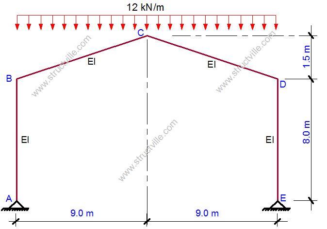
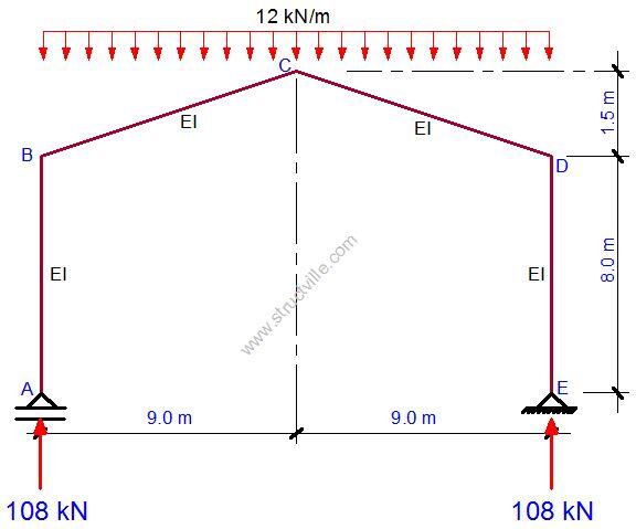
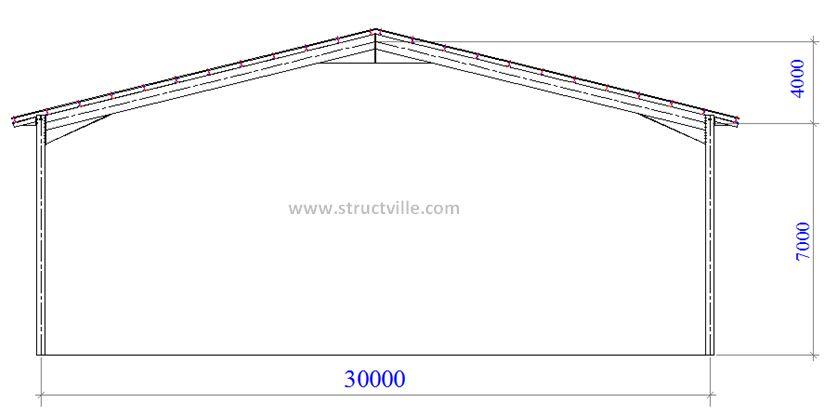
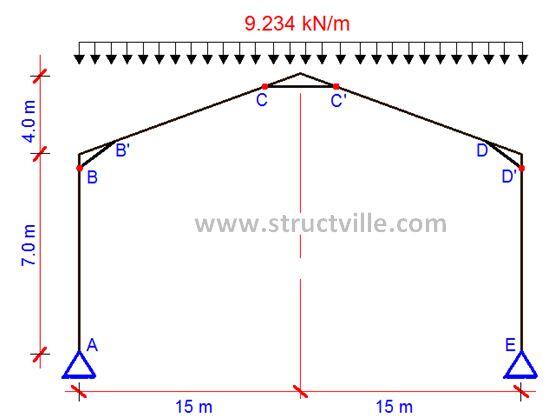
In this post, elastic first order analysis is performed on a single bay portal frame using Staad.Pro in order to calculate the reactions under vertical loads at ULS (see figure below). The actions on the portal frames are as given below;

gk = 2.31 kN/m
qk = 3 kN/m

Design load = (1.35 gk) + (1.5 × qk)

Roof load = (1.35 × 2.31) + (1.5 × 3.0) = 3.1185 + 4.5 = 7.6185 kN/m

PORTAL%2BFRAME%2BNHF

When analysed;

Vertical base reaction VEd = 118.263 kN
Horizontal base reaction HEd = 65.651 kN
Maximum Axial Load on rafter NR,Ed = 93.9 kN

Axial Compression in the rafter
According to clause 5.2.1(4), if the axial compression in the rafter is significant, then the αcr is not applicable.

The axial compression is significant if;

λ ̅  ≥ 0.3√((Afy)/NEd ) and this can be rearranged to show that the compression is significant if
NEd ≥ 0.09Ncr

NEd is the design axial load in the rafter
Lcr is the developed length of the rafter pair from column to column;
Lcr = 30/cos 15° = 31.058m
Ncr = (π2EI)/Lcr2 = (π2 × 210000 × 16000 × 104)/310582 = 343789.059 N = 344 kN

0.09Ncr = 0.09 × 344 = 30.94 kN
NEd = 93.9 kN > 30.94 kN, therefore axial load is significant.

When the axial force in the rafter is significant, a conservative measure of frame stability defined as αcr,est may be calculated. For frames with pitched rafters;

αcr,est = min(αcr,s,est ; αcr,r,est)

Where;
αcr,s,est is the estimate of αcr for the sway buckling mode
αcr,r,est is the estimate of αcr for the rafter snap-through buckling mode. This is only relevant when the frame has more than two bays or if the rafter is horizontal.

To calculate αcr, a notional horizontal force (NHF) is applied to the frame, and the horizontal deflection of the top of the column is determined under this load.

HNHF = VEd/200 = 118.263/200 = 0.591 kN


For the assessment of frame stability and for the assessment of deflections at SLS, the base may be modelled with a stiffness assumed to be a proportion of the column stiffness as follows;

  • 10% when assessing frame stability (10% of the column stiffness may be modelled by using a spring stiffness equal to 0.4EIcolumn/Lcolumn)
  • 20% when calculating deflections at SLS (20% of the column stiffness may be modelled by using a spring stiffness equal to 0.8EIcolumn/Lcolumn)

When the software cannot accommodate a rotational spring, the base fixity may be modelled by a dummy member of equivalent stiffness as shown below;

modelling%2Bof%2Bsupport
  • For assessing frame stability, the second moment of area of the dummy member should be taken as Ixx = 0.1Ixx,column
  • For calculating deflection at SLS, the second moment of area of the dummy member should be taken as Ixx = 0.2Ixx,column

In both cases, the length of the dummy member is 0.75Lcolumn and pinned at the far end.

On modelling the nominally pinned base using dummy members, the deflection below was obtained for the notional horizontal forces.

buckling%2Bamplification%2Bfactor%2Bfor%2Bportal%2Bframe

Therefore αcr = h / 200δNHF = 7000/(200 × 2.963) = 11.81
αcr,s,est = 0.8(1 – NEd/Ncr)
αcr = 0.8(1 – 93.9/344)11.81 = 6.869
αcr,s,est = 6.869 < 10

Therefore, second order effects are significant. Since αcr,s,est ≥ 3.0, the amplifier is given by;
[1/(1 – 1⁄αcr,est)] = [1/(1 – 1 ⁄ 6.869)] = 1.17

Note: If αcr,s,est is less than 3.0, second order analysis must be used. The simple amplification is not sufficiently accurate.

Therefore the modified partial factor of safety to account for second order effects are as follows;

γG = 1.17 × 1.35 = 1.5
γQ = 1.17 × 1.5 = 1.75

You can now use these modified partial factors to multiply the characteristic permanent and variable actions. The ultimate vertical action on the rafter (taking into account second order effects)is;

Roof load = (1.5 × 2.31) + (1.75 × 3.0) = 8.715 kN/m

Thank you for visiting Structville today and God bless you.