Theory of structures is a field of knowledge that is concerned with the determination of the effect of loads (actions) on structures. A structure in this context is generally regarded to be a system of connected members that can resist a load. Therefore in some programs, theory of structures is also referred to as structural analysis.
In application, theory of structures is usually interested in the computation of the deformations (displacements), internal forces, stresses, stability, support reactions, velocity, and accelerations of structures under load. The principles from applied mathematics, applied sciences (physics and mechanics), and materials science are usually employed in achieving this. The results of the analysis are used to evaluate the behaviour of a structure under the load, with the sole aim of verifying the integrity of the structure when in use. Therefore, theory of structures (structural analysis) is a key part of the engineering design of structures.

Theory of Structures and Structural Design
Buildings, bridges, and towers are prominent examples of the application of theory of structures in civil engineering. Ship and aircraft frames, tanks, pressure vessels, mechanical systems, and electrical supporting structures are examples of other engineering areas.
In the design of civil engineering structures for public use, safety, stability, serviceability, functionality, aesthetics, as well as economic and environmental constraints must be considered by the engineer. Thus, structural designs are expected to satisfy two basic limit states which are;
- Ultimate Limit State (ULS) and
- Serviceability Limit State (SLS)
According to limit state design, ULS requirements have to deal with issues like structural failure, overturning, buckling, instability, etc while SLS requirements have to deal with issues like deflection, vibration, cracking, etc, which affects the appearance and user experience of the building.
Usually, numerous independent evaluations of various solutions are required before a final decision on which structural scheme is best can be made. This approach to the design of structures, therefore, necessitates a basic understanding of material properties and the principles of mechanics that control material behaviour.
Following the proposal of a preliminary structural design, the structure must be examined to ensure that it has the requisite stiffness and strength. To effectively examine a structure, specific idealizations about how the components are supported and connected must be made. The loadings on a structure are calculated using codes and local requirements, and the forces and displacements in the members are calculated using theory of structures (structural analysis), which is the focus of this article.
The results of the structural analysis can then be utilised to redesign the structure, taking into consideration a more precise calculation of the self-weight and size of the members. As a result, structural design is based on a sequence of successive approximations, each of which necessitates a structural analysis.
Types of Structures
When modelling a real-life structure, it is necessary to represent the form of the structure in terms of idealized structural members, e.g. in the case of plane frames as beam elements, in which the beams, columns, etc. are indicated by line diagrams. The lines normally coincide with the centre lines of the members.
The decision as to which type of structural system to use rests with the structural designer whose choice will depend on the use of the structure, the materials to be used, and the original form of the structure as indicated by the architect. It is possible that more than one form of structural systems may be required to satisfy the requirements of the problem and the designer must then rely on experience and skill to choose the best solution. Examples of structural elements/systems are;
- Beams
- Columns
- Trusses
- Frames (portal frames, gable frames)
- Arches
- Cables
- Shear walls
- Continuum structures (shells, plates, domes, etc)
Beams
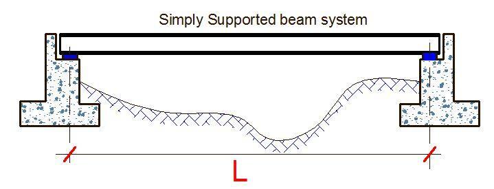
Beams are the commonest of all structural systems. They are usually made up of straight prismatic members that span in between supports that may be of any form. Beams are usually important in resisting transverse loads and achieve so by developing mainly bending moments and shear forces. Typically in structural design, beams can be made of reinforced concrete, steel, or timber.
See;
Design of reinforced concrete beams
Design of steel beams according to Eurocode 3
Design of steel beams according to BS 5950
Design of timber beam according to Eurocode 5
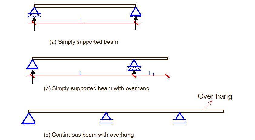
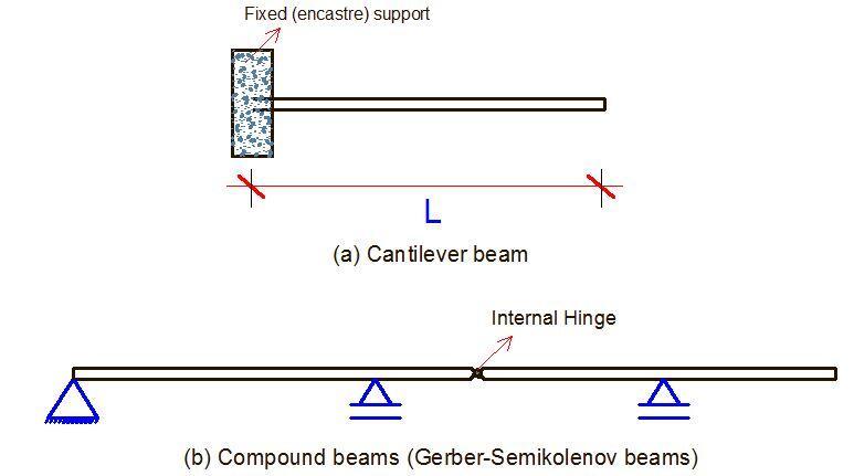
When a beam is fixed at one end and free at the other end, it is called a cantilever beam. It is also possible to have a beam extend beyond an external support and in this case, it is called a beam with an overhang (see Figure 3b and 3c). A beam that has intermediate supports is called a continuous beam, and when internal hinges are introduced to make it statically determinate, it is called a compound beam.
Columns
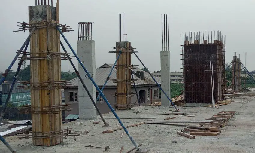
Vertical members that are used to resist axial compressive loads are referred to as columns. Hollow sections, H-sections, and I-sections are often used in the design of steel columns. Rectangular, circular, and square cross-sections with reinforcing rods are often used in the design of reinforced concrete columns. Occasionally, columns are subjected to both axial load and a bending moment. When a column is subjected to a bending moment in one direction, it is called a uniaxially loaded column, and when it is loaded in two directions, it is called a biaxially loaded column.
See also;
Design of steel columns for biaxial bending
Trusses
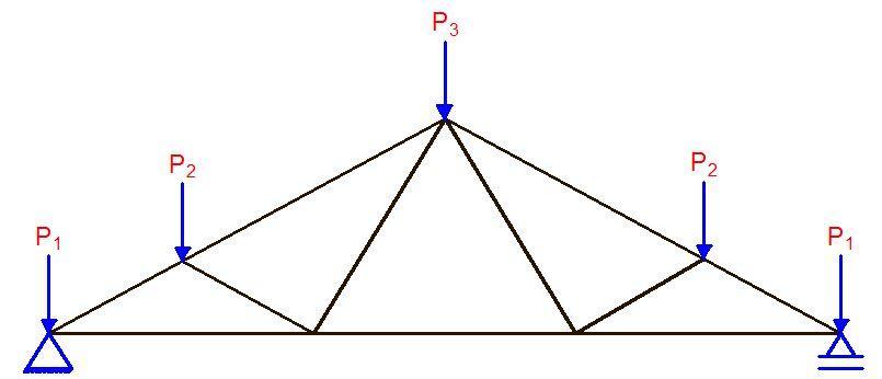
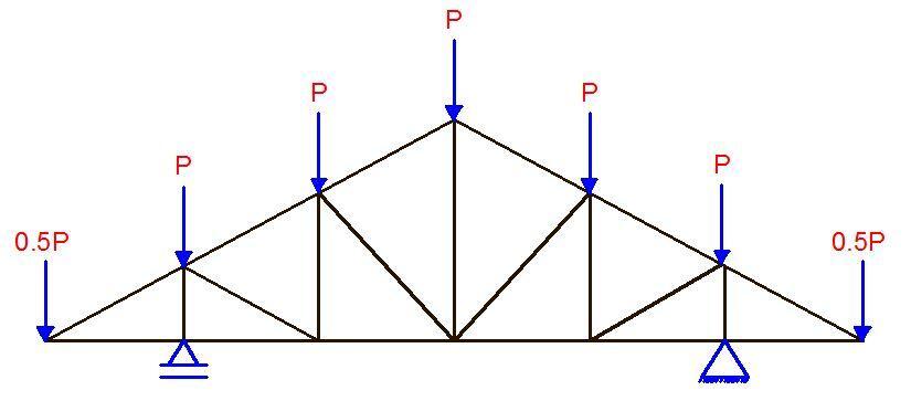
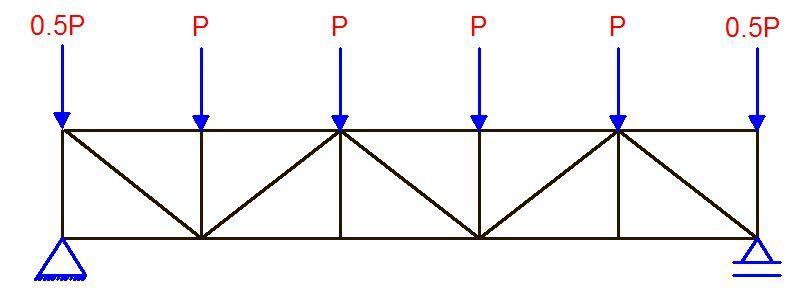
Trusses are arrangements of straight members connected at their ends. They resist loads by developing axial forces in their members but this is only true if the ends of the members are pinned together. The members in a truss are arranged to form a triangulated system so as to make them geometrically unchangeable, and also so that they will not form a mechanism. In trusses, loads are applied only at the joints.
When trusses have their ends fixed or welded together, secondary stresses develop and it is a form of analysis that favours the use of computer programs. Trusses provide practical and economical solutions to engineering problems. They can efficiently span greater lengths than beams, and hence can be found in roofs of buildings, bridges, etc. See design of steel roof trusses.
Rigid Frames
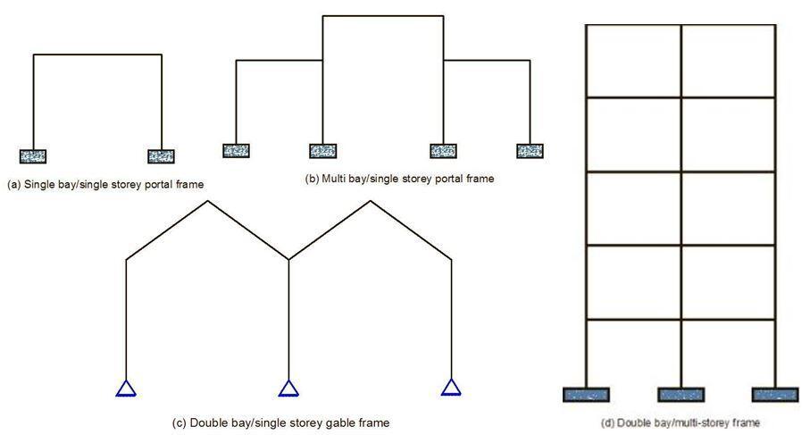
Unlike trusses which are pin-jointed frames that transmit axial forces only, rigid frames are designed to transfer both axial forces, shear forces, and bending moment across the members. Rigid frames are comparatively easier to erect since their construction usually involves the connection of steel beams and columns by bolting or welding.
In reinforced concrete design, the beams and columns are usually cast monolithically and it is relatively easy to construct the formwork. Rigid frames can be statically determinate or indeterminate and may involve multi-storey or multi-bay configuration as the case may be.
Arches
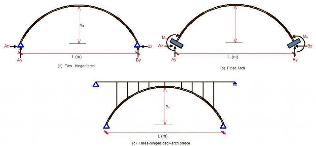
The arches are widely used in modern engineering due to their ability to cover large spans and their attractiveness from an aesthetic point of view. The greater the span, the more an arch becomes more economical than a truss. Materials of the modern arches are concrete, steel, and timber. Arches are mainly classified as three-hinged, two-hinged, and arch with fixed supports.
Arches carry most of their loads by developing compressive stresses within the arch itself and therefore in the past were frequently constructed using materials of high compressive strength and low tensile strength such as stones and masonry. Arches may be constructed in a variety of geometries; they may be semicircular, parabolic, or even linear where the members comprising the arch are straight.
Cables
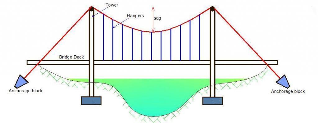
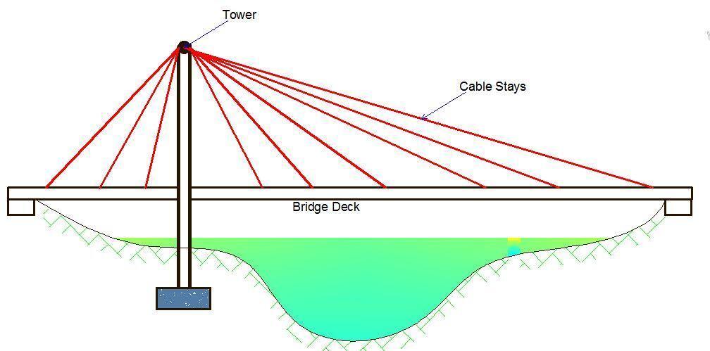
Cables are made from high-strength steel wires twisted together and present a flexible system, which can resist loads only by axial tension. The use of cables allows engineers to cover very large spans, especially in bridge design. In theory of structures, cables are deemed extremely efficient because they make the most effective use of structural material in that their loads are carried solely through tension through the wire. Therefore, there is no tendency for buckling to occur either from bending or from compressive axial loads.
A cable as a load-bearing structure has several features. One of them is the vertical load that gives rise to horizontal reactions, which, as in the case of an arch, is called a thrust. To accommodate the thrust it is necessary to have a supporting structure. It may be a pillar of a bridge or a tower or pylon. Cables are utilized in the form of suspension bridges, cable-stayed bridges, tower guy wires, etc.
Shear Walls
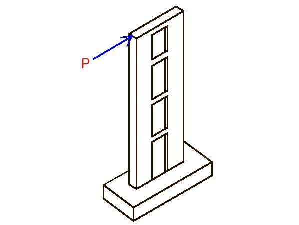
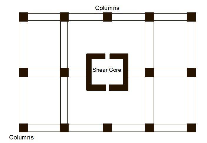
In tall buildings, there is a need to resist lateral forces which may arise from wind load or seismic forces, shear walls have been found to be a veritable solution. Shear walls may be planar solid or coupled and are usually provided alongside the frames of the structure. They are usually provided along the elevator shafts or stairwells. Apart from the use of computer-aided software, shear walls have been analysed using methods such as the continuous connection medium method, frame analogy method, etc.
Continuum structures
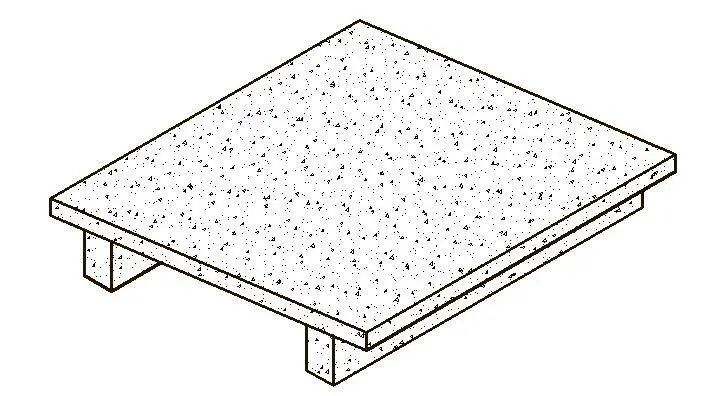
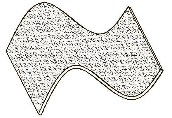
Continuum structures are made from a material having a very small thickness compared to its other dimensions. Examples of continuum structures are folded plate roofs, shells, floor slabs, etc. An arch dam is a three-dimensional continuum structure as are domed roofs, aircraft fuselages, and wings. Continuum mechanics is concerned with structures that are continuous in space. The simplest elements of this type are surface elements which have a thickness of a different order from the other two dimensions. Surface elements are termed plates if they have a plane form and shells if they form a general surface.
Loading of Structures
In theory of structures, we have different types of loading configuration and the commonest of them are;
- Concentrated loads (point loads)
- Uniformly distributed line loads (UDL)
Uniformly distributed area loads (full pressure loads) - Non-uniformly distributed load (e.g. trapezoidal and triangular loads)
Indirect actions
Concentrated loads
These are loads that act on a point in a structural system, and theoretically, they are like knife-edge loads acting at a précised point on a beam. However, in practice, these loads are usually distributed over a small area.
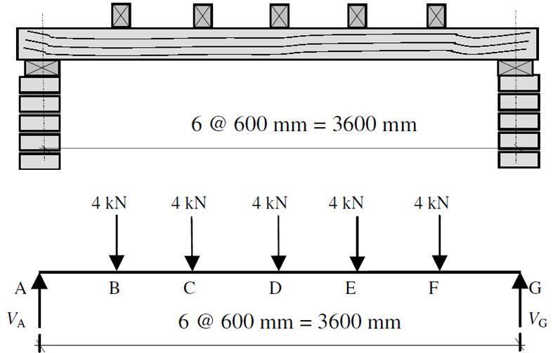
For example, a column that is supported on a suspended beam may be represented as a point load on the beam. Furthermore, the effect of secondary beams on primary beams is also treated as concentrated loads (see Figure 18). In Figure 18, Beam No 4 (axis 2-2) is a secondary beam that is supported on beams Nos 1 and 2 (axis A-A and B-B) which are primary beams that are directly supported on columns.
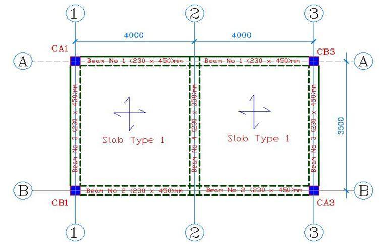
In the analysis, the loading on Beam No 4 is evaluated first, and the resultant support reactions are obtained. The reactions from Beam No 4 are applied as concentrated loads at the mid-span of beams Number 1 and 2. Note that secondary beams are usually shallower than primary beams. The equivalent loading on beams No 1 and 2 can be represented as shown in Figure 19.
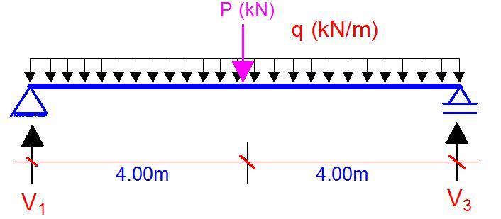
Where;
P = Support reaction from beam No 4
q = load from the slab, self-weight of the beam, blockwork loading, and finishes, etc
Also in trusses, all loads are converted to concentrated loads acting on the nodes. It is also very usual for wind loads to be converted to concentrated loads acting at the nodes of a structure (where the nodes are at the floor slab level).
Uniformly Distributed Line Loads (UDL)
UDLs are loads that are spread with the same intensity over a span of a structural element. They are usually distributed per unit length of the element and hence their units are of the form kN/m or N/m as the case may be. For example, the load from a slab that is simply supported or clamped at all sides to a beam that is supporting it may be converted to equivalent UDL using the following relationships (British Codes) given in Table 1. However, it is important to note that the actual load distribution from slab to beams is either triangular or trapezoidal.
Table 1: Equivalent loading from slab to beams according to British Codes
| Type of slab / Direction of span | Load to beam on long span (kN/m) | Load to beam on short Span (kN/m) |
| One-way slab | (nlx)/5 | (nlx)/2 |
| Two-way slab | (0.5nlx) × (1 – 0.333k2) | (nlx)/3 |
In Table 1 above, n stands for the uniformly distributed load on the slab at the ultimate limit state and is usually given by 1.4gk + 1.6qk (BS 8110-1:1997) or 1.35gk + 1.5qk (Eurocode 2). gk stands for the dead load while qk stands for the live load. k is the ratio between the length of the longer side (Ly) and the shorter side (Lx). This aspect ratio oftentimes is also used to define whether a slab is spanning in one direction or in two directions. Conventionally, if;
Ly/Lx > 2.0 (One way spanning slab)
Ly/Lx < 2.0 (Two way spanning slab).
You can refer to standard design textbooks for more complete information, but this is just to give us a little idea of how these loads come about.
Uniformly Distributed Area Loads (UDL)
Another variation of UDLs is pressure loads that are uniformly distributed over a unit area. These are typically the type of loads on slabs and plates, and even retaining walls. In fact, all walls are usually subjected to pressure loads, including earth intensity loads on foundations. The unit of pressure loads is kN/m2. The self-weight of slabs and finishes are typical examples of uniformly distributed loads. The live loads (imposed loads) specified on codes of practice are also uniformly distributed pressure loads.
In theory of structures, the analysis of plates subjected to uniformly distributed pressure load is usually carried out per unit strip and hence, internal forces such as moment and shear are expressed per metre strip (e.g. kNm/m, kN/m). Other examples of uniformly distributed loads are the surcharge loads that act at the back of retaining walls etc.
Non-uniformly distributed loads
These are loads that have varying intensity across the element on which they act. Examples of such loads are trapezoidal loads or triangular loads. Also, beams that do not have their full length subjected to full UDL can also be brought under this category (figure 1.3a). Triangular loads can come from block work on lintels and beams, and other types of loads and trapezoidal loads can come from earth pressure or hydrostatic force that is exerted on an element that is fully immersed in a fluid at rest.
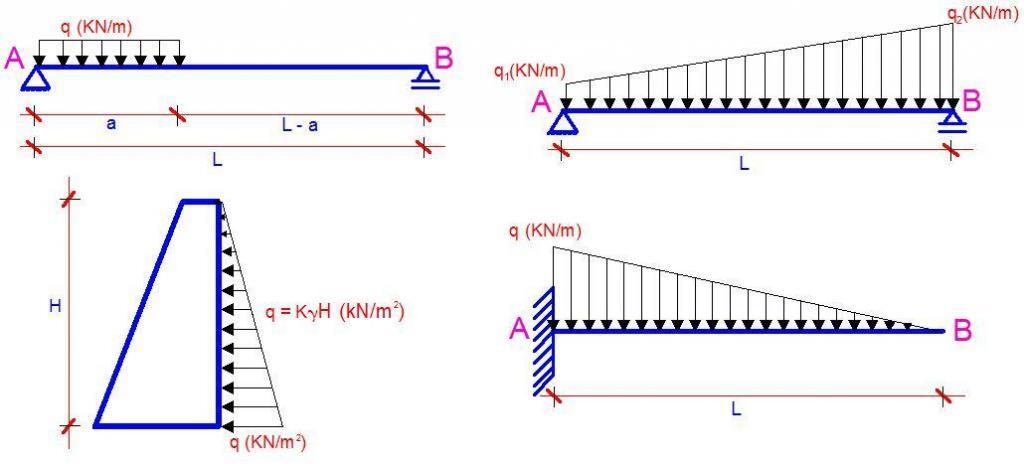
Figure 20(c) shows a gravity retaining wall that is retaining earth at the backface. The pressure due to the retained material varies with depth in a triangular manner as shown in the figure. In the figure;
q = earth pressure (kN/m2)
γ = Density of retained earth material (kN/m3)
K = Coefficient of active pressure (which may be computed using Coulomb’s or Rankine’s theory)
H = Height of the earth fill (m)
Indirect Actions (Loads)
Sometimes, other indirect actions on structures induce internal forces in the structure other than externally applied loads. The effects of these actions must be adequately assessed if the structure is to perform satisfactorily well. Some of these indirect loads are;
- Relative movement of supports (differential settlement)
- Temperature difference
- Imperfections
It is however worth knowing that problems such as differential settlement do not affect statically determinate structures. Such problems are only critical in statically indeterminate structures.
Types of supports in Theory of Structures
In theory of structures, a lot of support systems are available and the one that is adopted is dependent on the one that significantly represents the actual physical behaviour when constructed. The common types of support conditions are;
- Pinned supports
- Roller supports
- Fixed supports
- Tension or compression springs
- Elastic foundations
The first three are the commonest and they are the ones that are usually considered in theory of structures textbooks. In the selection of the types of support that will be used for analysis, the following may be used as guidelines;
Pinned Supports
These supports appear in the form of a hinge and is characterized by possessing vertical and horizontal reaction components. The joints of the support are free to rotate and as a result, pinned supports are not capable of resisting bending moment. In actual practice, situations that may be idealised as pinned supports are;
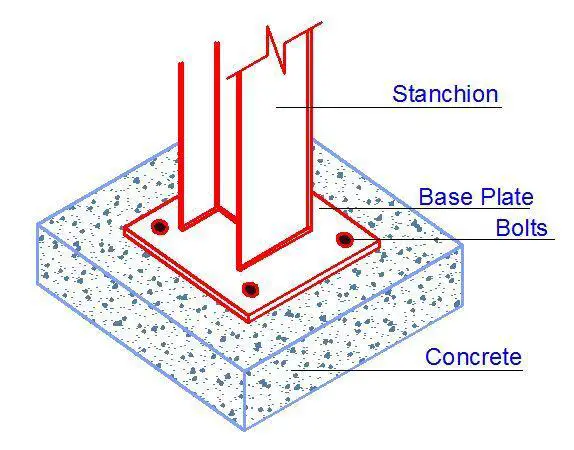
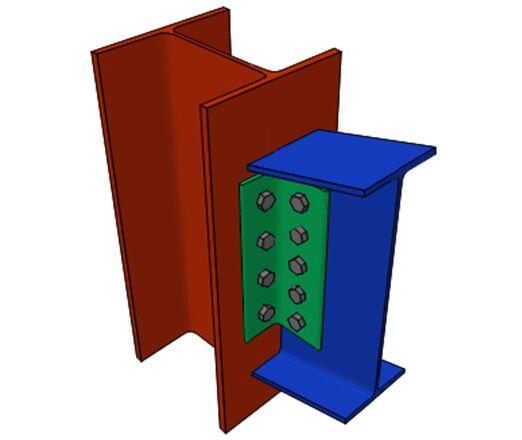
- Stanchions (steel columns) that are supported on base plates (Figure 21)
- Double angle cleat connection for beams and columns (Figure 22)
Roller supports
A single pinned support is sufficient to maintain the horizontal equilibrium of a beam and hence may not necessarily be provided at the other end. It may be advantageous to allow horizontal movement of the other end so that, for example, expansion and contraction caused by temperature variations do not cause additional stresses.
Such support may take the form of a composite steel and rubber bearing as shown in (Figure 23a) or consist of a roller sandwiched between steel plates (Figure 23b). This type of support is called roller support. It is assumed that such support allows horizontal movement and rotation but prevents movement vertically, up, or down. Roller supports resist only vertical loads.

Fixed Support
As the name implies, when the support of a structural member is built-in (fixed) such that no rotation or translation occurs, it is referred to as a fixed support. Fixed support resists vertical loads, horizontal loads, and moment and hence there are three reaction components. A beam-column connection that is welded with additional stiffeners can be idealised as fixed support for the beam (Figure 24a). Reinforced concrete columns and footing can also be idealised as fixed support if the base and the supporting soil are very stiff and rigid. (Figure 24b).
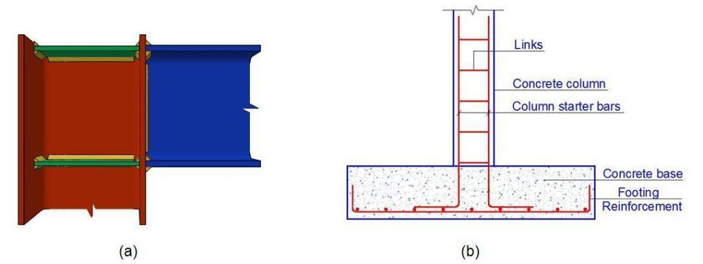
In theory of structures, these support conditions and their reaction components are shown in the Table below;

Tension or compression springs
Springs are also used in the idealisation of supports in theory of structures. When a structure is supported on a deformable body, springs can be used idealise the support condition. The stiffness of the spring is modelled to represent the strength of the deformable body. As a result, the interaction between the deformation of the support and the structural response of the supported member is captured in the analysis. A typical example is the use of Winkler’s springs in the idealisation of soils.
Elastic Foundations
When a structure is supported on a continuously deformable medium, it can be modelled as a structure on an elastic foundation. Beams on elastic foundations and plates on elastic foundations are popular topics in geotechnical and structural engineering. The can be used in the idealisation of raft foundations when using flexible approach. Elastic foundations are important in the modelling of soil-structure interaction.
Types of Structural Analysis
After the modelling of the structure and the supports, and assessment of the applied loads, the next step is to carry out an analysis to determine the internal forces and deformations induced in the structural members due to the applied load. Structural analysis usually encompasses one or more types of the following analytical methods.
Static linear analysis
This is the analysis that is carried out to determine the internal forces and displacements due to static loads (time-independent loads) while assuming that the structure is within the elastic state (Hooke’s law is being obeyed).
Non-Linear Static analysis
This is the analysis that is carried out to determine the internal forces and displacements in a structure when it is subjected to static loads and when we assume non-linear conditions. Non-linear analysis can be in the following forms;
Physical – The material has exceeded the yield point and Hooke’s law is no longer being obeyed.
Geometrical – Structure is subjected to large displacement, and analysis is based on the deformed structure
Structural – Analysis for structures with gaps, unbalanced constraints etc
Mixed non-linearity – A combination of the above-mentioned non-linearities
Buckling Analysis
This is the analysis that is carried out to determine the critical load (or critical load factor) including the corresponding buckling mode shapes of structures subjected to compressive loads. It is important is assessing the stability of structures.
P-delta Analysis
This analysis takes into account the additional moments due to compressive loads on the displacement caused by the lateral loads. This happens in tall and flexible structures. Thus, the analysis is also based on the deformed system (non-linear).
Free Vibration Dynamic Analysis
The purpose of this vibration analysis is to obtain the natural frequencies (eigenvalues) and the corresponding mode shapes (eigenfunctions).
Time-history Analysis
This analysis is carried out to determine the response of a structure that is subjected to arbitrarily time-varying loads.
Pushover Analysis
Pushover analysis is a non-linear approach used to determine structural capacity under static horizontal loads that grow until the structure collapses. It is a static process that estimates seismic structural deformations using a reduced nonlinear technique. During earthquakes, structures redesign themselves.
The dynamic forces on a structure are moved to other components as individual components yield or fail. A pushover analysis replicates this phenomenon by applying loads until the weak link in the structure is discovered, then changing the model to account for the structural changes generated by the weak link.
The loads are redistributed in the second iteration. The structure is pushed once more until the second weak link is found. This approach is repeated until a yield pattern for the entire structure is found under seismic loading. Pushover analysis yields several capacity curves based on the variation of base shear as a function of the displacement of a control point on the structure.
Static Determinacy of Structures
A structure is stable when it maintains balance in force and moment. As a result, we know that from statics, if a structure is to be at equilibrium,
∑Fy = 0; ∑Fx = 0; ∑Mi = 0 ——— (1)
Where;
∑Fy = Summation of the vertical forces
∑Fx = Summation of the horizontal forces
∑Mi = Summation of the moment of force components acting in the x-y plane passing through point i.
When the number of constraints in a structure permits the use of the equation of statics (equation 1) to analyse the structure, the structure is said to be statically determinate. Otherwise, it is statically indeterminate, and additional equation(s) which are derived from the load-deformation relationships are used for analysis. For the records, there are two well-known approaches to the analysis of indeterminate structures and they are;
- Flexibility Methods – When the structure is analysed with respect to unknown forces
- Stiffness Methods – when the structure is analysed with respect to unknown displacements
A structure may be indeterminate due to redundant components of reaction and/or redundant members. Note that a redundant reaction or member is one which is not really necessary to satisfy the minimum requirements of stability and static equilibrium. However, redundancy is desirable in structures because it can be a cheaper alternative to statically determinate structures. The degree-of-indeterminacy is equal to the number of unknown member forces/external reactions which are in excess of the equations of equilibrium available to solve for them.



Thanks. I got the required information
You are well done
I appreciate this.
Grateful all the way!
Great information!