8.7 C
New York
Friday, November 22, 2024
Home Blog Page 64

Design of Doubly Reinforced Beams | Worked Example

Doubly reinforced beams are reinforced concrete beams that incorporate both compression steel (in the compression zone) and tension steel (in the tension zone). This design is typically employed when the required moment capacity of a beam exceeds that which can be provided by singly reinforced beams (those with only tension steel).  

In singly reinforced concrete beams without moment redistribution, k = MEd/fckbd2 is limited to k’ = 0.167. Therefore, once the value of k > k’, the beam must be designed as a doubly reinforced beam. In doubly reinforced beams, compression steel reinforcements are required because the concrete section (in compression) by itself cannot develop the required moment of resistance.

However, when there is a moment redistribution in the section, k > k’ where k’ is dependent on the moment redistribution ratio (δ) and is given by:

k’ = 0.6δ – 0.18δ2 – 0.21 where δ ≤ 1.0

In all cases, it is recommended that k’ be limited to 0.167 to ensure ductile failure. It is important to understand that the redistribution of moments derived from elastic analysis of a reinforced concrete structure accounts for the plastic behaviour of the material as it approaches its ultimate limit state.

To facilitate this plastic response, concrete sections must be designed to permit the formation of plastic hinges upon the yielding of tensile reinforcement. This approach ensures a ductile structure characterized by a gradual failure at the ultimate limit state, rather than a sudden, catastrophic collapse due to compressive failure of the concrete.

To guarantee the formation of plastic hinges and the necessary section rotation for ductile behaviour, Eurocode 2 imposes limitations on the maximum neutral axis depth, xbal. These restrictions ensure that the tensile steel experiences high strains and this promotes the desired plastic response.

The permissible value of xbal is determined based on the desired degree of moment redistribution. According to Eurocode 2, the limit is xbal ≤ 0.8(δ – 0.44)d for fck ≤ C50. However, this limit was modified to xbal as xbal ≤ (δ – 0.4)d in the UK Annex to the EC2.

Design of Doubly Reinforced Beam

To ensure a ductile response and prevent sudden compressive failure of the concrete, it is required that the neutral axis depth should not exceed 0.45 times the effective depth (0.45d). This guideline is typically adopted in the design of sections incorporating compression reinforcement (doubly reinforced beam sections).

Rectangular stress block for doubly reinforced beam

In the design of reinforced concrete beams, if the design ultimate moment is greater than the ultimate moment of resistance i.e. MEd > Mlim, then compression reinforcement is required. Provided that d2/x ≤ 0.38 (i.e. compression steel has yielded) where d2 is the depth of the compression steel from the compression face and x = (d − z)/0.4

The area of steel in compression, As2, is given by:
As1 = (MEd – Mlim) / (fsc(d – d2)) —- (1)
fsc = Esεsc ≤ 0.87fyk
εsc = steel compressive strain = 0.0035(x – d’)/x
Es = Modulus of elasticity of steel = 200000 N/mm2

Area of tension reinforcement:
As1 = Mlim / (0.87fykz) + As2 (fsc/0.87fyk) —- (2)

Where:
MEd = Design bending moment of the section
Mlim = 0.167fckbd2
z = d[0.5+ √(0.25 – 0.882k’)]
where
k’ = 0.167

Design Example of a Doubly Reinforced Beam

To show how this is done, let us consider the flexural design of support A of the beam loaded as shown below. The depth of the beam is 600 mm, and the width is 400 mm.
fck = 35 N/mm2 ; fyk = 500 N/mm2; concrete cover = 40mm

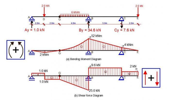
DOUBLY%2BREINFORCED%2BBEAM%2B%2528QUESTION%2529
DOUBLY%2BREINFORCED%2BBEAM%2B%2528BMD%2529


Top reinforcement (Hogging moment)

Support A (No moment redistribution)
Effective depth (d) = 600 – 40 – 16 – 10 = 534 mm
d2 = 40 + 8 + 10 = 58 mm

MEd = 761.24 kNm

But since the flange is in tension, we use the beam width to calculate the value of k (this applies to all support hogging moments)
k = MEd / (fckbwd2) = (761.24 × 10⁶) / (35 × 400 × 5342) = 0.1906
z = d[0.5+ √((0.25 – 0.882(0.167))] = 0.82d = 0.82 × 534 = 437.88 mm
x = (d − z)/0.4 = (534 − 437.88)/0.4 = 240.3 mm

d2/x = 58/240.3 = 0.241 < 0.38 (therefore reinforcement bar has yielded and fsc = 0.87fyk)

Since k < 0.167, compression is required
Area of compression reinforcement AS2 = (MEd – Mlim) / (0.87fyk (d – d2))

Mlim = 0.167fckbd2 = (0.167 × 35 × 400 × 5342) × 10-6 = 666.69 kNm

AS2 = ((761.24 – 666.69) × 106) / (0.87 × 500 × (534 – 58)) = 457 mm2
Provide 3H16 Bottom (Asprov = 603 mm2)

Area of tension reinforcement As1 = MRd / (0.87fyk z) + AS2
Where z = d[0.5+ √(0.25 – 0.882K’)]
K’ = 0.167
z = d[0.5+ √((0.25 – 0.882(0.167))] = 0.82d

As1 = MRd / (0.87fyk z) + AS2 = ( 666.69 × 10⁶) / (0.87 × 500 × 0.82 × 534) + 457 mm2 = 3957 mm2

Provide 3H32mm + 4H25 mm Top (ASprov = 4376 mm2)

Comparison of Shear Design to EC2 and BS 8110

Eurocode 2 uses the variable strut inclination method for shear design. It is slightly more complex than the procedure in BS 8110 but can result in savings in the amount of shear reinforcement required.

Like BS 8110, Eurocode 2 models shear behaviour using the truss analogy in which the concrete acts as the diagonal struts, the stirrups act as the vertical ties, the tension reinforcement forms the bottom chord, and the compression steel/ concrete forms the top chord. Whereas in BS 8110 the strut angle has a fixed value of 45°, in EC2 it can vary between 21.8° and 45° and it is this feature which is responsible for possible reductions in the volume of shear reinforcement.

Shear design Eurococde 2

The concrete strut angle changes with respect to the magnitude of the shear force applied. The angle decreases with a reduction in shear stress, with a minimum angle of 21.8° (where cot = 2.5) which happens to be the most frequently used design strut angle.

Shear design in Eurocode 2 often involves comparing the design shear stress (vEd) to the concrete shear resistance (vRd,c). If vEd < vRd,c then in the case of one-way spanning slabs no shear reinforcement is required; in the case of beams nominal shear reinforcement is required. vRd,c is dependent on the amount of design tensile reinforcement and the design concrete strength.

If vEd < vRd,max (ie vRd,cot θ = 2.5), then the shear reinforcement may be calculated as:
Asw/s ≥ vEd/(0.87 × fyk × z × cot 2.5)

If vEd > vRd,max (ie vRd,cot θ = 2.5), then checks against vRd,cot θ = 1.0 and determination of θ are required.
If vEd > vRd,cot θ = 1.0 then a larger section or greater concrete strength is required.

Where applied shear stresses are higher, one has to check against the maximum allowable shear stress at the maximum strut angle of θ = 45º (e.g. 5.28 MPa for a C30/37 concrete when cot θ = 1.0) and where necessary determine the actual intermediate strut angle, θ.

Solved Example for Shear Design

For the beam loaded as shown below and disregarding load factors, we are going to obtain the shear reinforcement required for section A. The shear force at the centreline of support has been adopted for this design, and the area of tension steel provided at this section As1 = 4825 mm2.

DOUBLY%2BREINFORCED%2BBEAM%2B%2528QUESTION%2529
DOUBLY%2BREINFORCED%2BBEAM%2B%2528BMD%2529


Design Data
:
Concrete Strength = 35 N/mm2
Grade of steel = 460 N/mm2
Width of beam = 400mm
Depth of beam = 600mm
Effective depth = 543mm
Area of tension steel provided at section As1 = 4825 mm2

Shear Design to EC2

Support A; VEd = 500.46 kN

VRd,c = [CRd,c.k.(100ρ1 fck)(1/3) + k1cp]bw.d ≥ (Vmin + k1cp) bw.d

CRd,c = 0.18/γc = 0.18/1.5 = 0.12
k = 1 + √(200/d) = 1 + √(200/543) = 1.606 > 2.0, therefore, k = 1.606
Vmin = 0.035k(3/2) fck0.5
Vmin = 0.035 × (1.606)1.5 × 350.5 = 0.421 N/mm2
ρ1 = As/bd = 4825/(400 × 543) = 0.022 > 0.02; Therefore take 0.02

σcp = NEd/Ac < 0.2fcd (Where NEd is the axial force at the section, Ac = cross-sectional area of the concrete), fcd = design compressive strength of the concrete.) Take NEd = 0

VRd,c = [0.12 × 1.606 (100 × 0.02 × 35 )(1/3)] 400 × 543 = 172511.992 N = 172.511 kN

Since VRd,c (172.511 kN) < VEd (500.46 kN), shear reinforcement is required.
The compression capacity of the compression strut (VRd,max) assuming θ = 21.8° (cot θ = 2.5)

VRd,max = (bw.z.v1.fcd) / (cot⁡θ + tanθ)
V1 = 0.6(1 – fck/250) = 0.6(1 – 35/250) = 0.516
fcd = (αcc fck) / γc = (0.85 × 35) / 1.5 = 19.833 N/mm2
Let z = 0.9d

VRd,max = [(400 × 0.9 × 543 × 0.516 × 19.833) / (2.5 + 0.4)] × 10-3 = 689.83 kN

Since VRd,c < VEd < VRd,max

Hence Asw / S = VEd / (0.87.Fyk.z.cot θ) = 500460 / (0.87 × 460 × 0.9 × 543 × 2.5 ) = 1.0235

Minimum shear reinforcement;
Asw / S = ρw,min × bw × sinα (α = 90° for vertical links)
ρw,min = (0.08 × √(Fck)) / Fyk = (0.08 × √35) / 460 = 0.001028
Asw/Smin = 0.001028 × 400 × 1 = 0.411
Maximum spacing of shear links = 0.75d = 0.75 × 543 = 407.25

Provide X10mm @ 150mm c/c as shear links (Asw/S = 1.0467) Ok!!!!

Shear Design to BS 8110-1:1997

Design of support A
Ultimate shear force at the centerline of support
V = 500.46 kN

Using the shear force at the centreline of support;
Shear stress = V/(bd ) = (500.46 × 10³) / (400 × 543) = 2.304 N/mm2

v(2.304 N/mm2 ) < 0.8√fcu (4.732 N/mm2 ). Hence, the dimensions of the cross-section are adequate for shear.

Concrete resistance shear stress
vc = 0.632 × (100As/bd)1/3 (400/d)1/4
(100As/bd) = (100 × 4825) / (400 × 543) = 2.221 < 3 (See Table 3.8 BS 8110-1;1997)
(400/d)1/4 = (400/543)1/4 = 0.926; But for members with shear reinforcement, this value should not be less than 1. Therefore take the value as 1.0

vc = 0.632 × (2.221)1/3 × 1.0 = 0.8245 N/mm2
For fcu = 35 N/mm2, vc = 0.8245 × (35/25)1/3 = 0.922 N/mm2

Let us check;
(Vc + 0.4)1.322 N/mm2 < v(2.304 N/mm2) < 0.8√fcu (4.732 N/mm2)

Therefore, provide shear reinforcement links.
Let us try 2 legs of Y10mm bars (Area of steel provided = 157 mm2

Asv/Sv = (0.95 × Fyv) / (bv (v – vc)) = [400 × (2.304 – 0.922)] / (0.95 × 460) = 1.264

Maximum spacing = 0.75d = 0.75 × 543 = 407.25 mm
Provide Y10mm @ 100 mm c/c links as shear reinforcement (Asv/Sv = 1.57)

We can therefore see that disregarding load factor and flexural design requirements, EC2 is more economical than BS 8110 in shear design, and in this case study by about 19%.

Free MATLAB Code for Flexural Design of R.C. Sections According to EC2

In this post, I am going to present an extremely simplified MATLAB code for carrying out flexural design of reinforced concrete beams (rectangular or flanged) according to Eurocode 2. Before you can use this code, you must carry out your analysis and obtain your design forces and moments. You can just copy the code and paste on your MATLAB script. There are no external functions to be called for the program.


% ANALYSIS AND DESIGN OF RECTANGULAR AND FLANGED BEAMS PER EUROCODE 2
% THIS PROGRAM WILL CALCULATE THE AREA OF REINFORCEMENT REQUIRED, AND ALSO DO THE DEFLECTION VERIFICATION USING THE DEEMED TO SATISFY RULES OF EC2

clc
disp(‘THIS PROFORMA WAS WRITTEN BY O.U.R UBANI’)
disp(‘DOWNLOADED FROM WWW.STRUCTVILLE.COM’)
disp(‘ANALYSIS AND DESIGN OF BEAMS PER EUROCODE 2’)

% INPUT MATERIAL PROPERTIES
Fck = input(‘Enter the grade of concrete (N/mm^2)Fck  = ‘);
Fyk = input(‘Enter the yield strength of steel (N/mm^2)Fyk = ‘);

% INPUT DESIGN MOMENT
MEd = input(‘Enter the ultimate design moment (KNm) MEd = ‘);

% INPUT SECTION AND DESIGN PROPERTIES
h = input(‘Enter the depth of beam (mm)h = ‘);
b = input(‘Enter the effective flange width of the beam (mm)b = ‘);
bw = input(‘Enter the beam width (mm)bw = ‘);
Cc = input(‘Enter concrete cover (mm) = ‘);
dr = input(‘Enter the diameter of reinforcement (mm) = ‘);
dl = input(‘Enter the diameter of links = ‘);

% CALCULATION OF EFFECTIVE DEPTH

disp(‘Effective depth d (mm)’)
d = h-Cc-(dr/2)-dl % Effective depth
disp(‘Depth of reinforcement from the face of concrete’)
do = Cc+dl+(dr/2)

% ANALYSIS FOR INTERNAL STRESSES
ko = 0.167;
k = (MEd*10^6)/(Fck*b*d^2)
if k>ko
disp(‘Since k > ko, Compression reinforcement is required’)
Mcd = (Fck*b*d^2*(k-ko))*10^(-6)
As2 = (Mcd*10^6)/(0.87*Fyk*(d-do))
z = 0.5*d*(1+sqrt(1-3.53*ko))
As1 = ((ko*Fck*b*d^2)/(0.87*Fyk*z))+ As2
else
disp(‘Since k < ko, No Compression reinforcement is required’)
disp(‘Lever arm (la)’)
la = 0.5+sqrt(0.25-0.882*k)
if la>0.95
disp(‘Since la > 0.95,’)
la = 0.95
else
la = 0.5+sqrt(0.25-0.882*k)
end
As1 =(MEd*10^6)/(0.87*Fyk*la*d)
end

% MINIMUM AREA OF STEEL REQUIRED
fctm = 0.3*(Fck^(2/3)) %MEAN TENSILE STRENGTH OF CONCRETE (TABLE 3.1 EC2)
ASmin = 0.26*(fctm/Fyk)*bw*d
if ASmin < 0.0013*bw*d
ASmin = 0.0013*bw*d
end
if As1<ASmin
As1 = ASmin
else
disp(‘Since As1 > Asmin, provide As1 which is the area of steel required’)
end

Asprov1 = input(‘Enter area of tension steel provided (mm^2) = ‘);
Asprov2 = input(‘Enter area of compression steel provided if any (mm^2) = ‘);


% CHECK FOR DEFLECTION

disp(‘DO YOU WANT TO CHECK FOR DEFLECTION?’)
G = input(‘ENTER (1) FOR YES OR (0) FOR NO = ‘);
if G == 1;
    disp(‘CHECK FOR DEFLECTION’
disp(‘BASIC SPAN/EFFECTIVE DEPTH RATIO (K)’)
disp(‘CANTILEVER = 0.4’)
disp(‘SIMPLY SUPPORTED = 1.0’)
disp(‘SIMPLY SUPPORTED AND FIXED AT ONE END = 1.3’)
disp(‘FIXED AT BOTH ENDS = 1.5’)
K = input(‘Enter the selected value of k = ‘);
L = input(‘Enter the deflection critical length of the member (mm) = ‘);
 
disp(‘Fs is the stress in tensile reinforcement under service loading’)
Fs = (310*Fyk*As1)/(500*Asprov1)
disp(‘Bs = 310/Fs’)
Bs = 310/Fs
disp(‘P is the reinforcement ratio in the section (Asprov1)/(b*d)’)
P = (Asprov1)/(b*d)
disp(‘Po = sqrt(Fck)/1000’)
Po = sqrt(Fck)/1000
P1 = (Asprov2)/(b*d)
if 
  P <= Po
  I_deflection = K*(11+(1.5*sqrt(Fck)*(Po/P)) + 3.2*sqrt(Fck)*((Po/P)-1)^1.5)
else
    I_deflection = K*(11+(1.5*sqrt(Fck)*(Po/(P-P1))) + 3.2*sqrt(Fck)*((Po/P)-1)^1.5)
end
CV = input(‘Is the beam is flanged? (1) for YES and (0) for NO = ‘)
if CV == 1
disp(‘S is the ratio of beff/bw’)
S = b/bw
  bn = (11-(b/bw))/10
 
  if S >= 3.0;
   K_deflection = Bs*0.8* I_deflection
else
   K_deflection = Bs*bn* I_deflection
  end
   if L>7000
    Limiting_deflection = (7000/L)*K_deflection
else
    Limiting_deflection =  K_deflection
end
  end
else
  Limiting_deflection =   Bs*I_deflection
end
Actual_deflection = L/d
if 
Limiting_deflection > Actual_deflection
    disp(‘Deflection is satisfactory’)
else
    disp(‘DEFLECTION IS NOT SATISFACTORY !!!!! Increase depth of beam, or increase area of steel, or both. Then rerun proforma’)


end


2.0 MATLAB CODE FOR SHEAR DESIGN ACCORDING TO EC2

% SHEAR DESIGN IN EUROCODE 2
clc
disp(‘SHEAR DESIGN ACCORDING TO EC2′)
disp(‘THIS PROFORMA WAS WRITTEN BY O.U.R. UBANI’)

% MATERIALS PROPERTIES
Fck = input(‘Enter the grade of concrete (N/mm^2) = ‘);
Fyk = input(‘Enter the yield strength of steel (N/mm^2) = ‘);

VEd = input(‘Enter the value of shear force at ULS (KN) = ‘);

% SECTION PROPERTIES
h = input(‘Enter the depth of beam (mm) = ‘);
bw = input(‘Enter the beam width (mm) = ‘);
Cc = input(‘Enter concrete cover (mm) = ‘);
dr = input(‘Enter the diameter of reinforcement (mm) = ‘);
dl = input(‘Enter the diameter of links = ‘)
d = h-Cc-(dr/2)-dl % Effective depth
do = Cc+dl+(dr/2)

% CALCULATION OF THE SHEAR CAPACITY OF THE SECTION WITH NO SHEAR REINFORCEMENT
 
Asprov1= input(‘Enter the area of steel provided in the shear zone (mm^2) = ‘) % The reinforcement must exceed the design anchorage length by at least the effective depth
Crd = 0.12
k1= 1+sqrt(200/d)
if k1>2
k1=2
end
disp(‘Reinforcement ratio’)
P1 = (Asprov1/(bw*d))
if P1>0.02
P1 = 0.02

end

% THIS SECTION IS TO BE CONSIDERED IF THERE IS AXIAL FORCE IN THE SECTION
disp(‘Axial force in the section’)
N = input(‘Enter the value of AXIAL FORCE IF ANY(+VE FOR COMP, AND -VE FOR TENSION)(kN) = ‘)
disp(‘Axial stress in the section (Ds)’)
Ds = (N*1000)/(bw*h)
if Ds > (0.2*0.85*Fck)/1.5
Ds = (0.2*0.85*Fck)/1.5
end
k2 = 0.15;
disp(‘Minimum shear stress in the section (N/mm^2)’)
Vmin = 0.035*k1^(1.5)*sqrt(Fck)
disp(‘Concrete resistance shear stress (VRd) (N/mm^2)’)
VRdQ = ((Crd*k1)*(100*P1*Fck)^(1/3)*(bw*d))/1000 % SHEAR FORCE CONTRIBUTION
VRdN = ((k2*Ds)*(bw*d))/1000 % AXIAL FORCE CONTRIBUTION
VRd = VRdQ + VRdN % TOTAL SHEAR RESISTANCE
if VRd < ((Vmin+(k2*Ds))*(b*d))/1000
VRd = ((Vmin+(k2*Ds))*(b*d))/1000
end
if VRd>VEd
disp(‘Since VRd > VEd’)
disp(‘NO SHEAR REINFORCEMENT REQUIRED, PROVIDE NOMINAL LINKS’)
else
if VRd<VEd
disp(‘Since  VRd < VEd’)
disp(‘SHEAR REINFORCEMENT REQUIRED, CALCULATE COMPRESSION STRUT CAPACITY’)
disp(‘Assume strut angle (thetha) = 21.8 deg, cot(thetha)= 2.5’)
thetha = 21.8
V1 = 0.6*(1-(Fck/250))
disp(‘Design compressive strength of concrete (fcd) (N/mm^2)’)
fcd = 0.567*Fck
z = 0.9*d
disp(‘Maximum capacity of compression strut (KN)’)
VRDmax = ((b*z*V1*fcd)/(2.9))/1000
if VRDmax > VEd
disp(‘Since VRDmax > VEd’)
disp(‘OK! Calculate diameter and spacing of links’)
ASMINlinks_to_spacing = ((0.08*sqrt(Fck))/Fyk)*b
ASlinks_to_spacing = (VEd*1000)/(z*0.87*Fyk*2.5)
else
disp(‘Since VRDmax > VEd, it means we need a higher strut angle (beta)’)
disp(‘By calculating the strut angle’)
disp(‘Shear stress at the section (N/mm^2)’)
v = (VEd*1000)/(b*d)
beta = (0.5)*asind((v)/(0.153*Fck*(1-(Fck/250))))
if beta>45
disp(‘Since beta < 45 deg, SECTION INADEQUATE FOR SHEAR, INCREASE DEPTH !!!!!’)
   else
disp(‘The ratio of Area of steel/spacing of links’)
ASlinks_to_spacing = (VEd*1000)/(z*0.87*Fyk*cotd(beta))
end
end
end
Area_of_legs = input(‘Enter the area of number of legs selected = ‘)
Spacing = input(‘Enter the spacing = ‘)
disp(‘CHECK’)
T = Area_of_legs/Spacing
if T > ASlinks_to_spacing
disp(‘Shear reinforcement is ok’)
else
disp(‘Increase area of steel, or reduce spacing’)
end
end  


Like us on Facebook at www.facebook.com/structville 


ALSO IN THIS BLOG
Analysis and Design of Continuous R.C. Raker Beam for Stadium using EC2
Two Approaches to the Calculation of Deflection in EC2; Choose a Faster Approach for Yourself

Two Approaches to the Calculation of Deflection in Eurocode 2

The verification of deflection is an important serviceability check in reinforced concrete design. Most designs codes adopt the ‘deemed to satisfy’ rules which limit the deflection to an acceptable depth using Basic Span/Effective depth ratio. This is generally more frequently employed than carrying out the rigorous exact calculation of deflection which is however not
very reliable.

Eurocode 2 has its own set of deemed to satisfy rules, and there are two approaches to calculation of deflection which yields the same result. It is not like that they are two different formulars, but they are just one formular expressed in two different ways. This post shows the two approaches, so that you can select the one you deem fast enough for carrying out your manual calculations.

According to Clause 7.4.2 of EN 1992-1-1, we can verify deflections in the absence of exact calculations using deemed to satisfy basic span/effective depth (limiting deflection to depth/250);

READ ALSO IN THIS BLOG…
On the Deformation of Statically Indeterminate Frames Using Force Method

Lateral Deflection of Multi-Storey Buildings Under the Action of Wind Load

(a) BY USING THE FIRST APPROACH
Actual L/d must be ≤ Limiting L/d × βs

The limiting basic span/ effective depth ratio is given by;
L/d = K [11 + 1.5√(fck) ρ0/ρ + 3.2√(fck ) [(ρ0 / ρ) – 1](3⁄2) ] if ρ ≤ ρ0 ———– (1)

L/d = K [11 + 1.5√(fck) ρ0/(ρ – ρ’) + 1/12 √(fck) (ρ0/ρ)(1⁄2) ] if ρ > ρ0 ———— (2)
Where;
L/d is the limiting span/depth ratio
K = Factor to take into account different structural systems
ρ0 = reference reinforcement ratio = 10-3√(fck)
ρ = Tension reinforcement ratio to resist moment due to design load
ρ’ = Compression reinforcement ratio

The value of K depends on the structural configuration of the member, and relates the basic span/depth ratio of reinforced concrete members. This is given in the Table below;

Table%2Bof%2Bbasic%2Bspan%2Bto%2Beffective%2Bdepth%2Bratio%2BEC2

βs = (500 Asprov)/(Fyk Asreq) ———- (3)

(b) BY USING THE SECOND APPROACH
L/d ≤ Basic ratio × αs × βs
Where the basic ratio = 20K

Approach%2B2%2BBasic%2Bratio

Modification factor αs which depends on the concrete strength fck and reinforcement percentages, is given by:

For 100As/bd < 0.1fck0.5;
αs = 0.55 + 0.0075fck/(100As/bd) + 0.005fck0.5[ fck0.5/ (100As/bd) – 10]1.5 —————- (4)

For 100As/bd ≥ 0.1fck0.5;
αs = 0.55 + 0.0075fck/[100(As – As’)/bd) + 0.013fck0.25 (100As’/bd)]0.5 (for doubly-reinforced sections) —————- (6)

αs = 0.55 + 0.0075fck/(100As/bd) (for singly-reinforced sections) —————- (7)

Modification factor βs = 310/σs —————- (8)
Where:
σs is the stress in the tension reinforcement under the characteristic loading. It will normally be conservative to assume;
βs = (500/fyk)(As,prov/As,req) for values of (As,prov/As,req)≤ 1.5 —————- (9)

Important hints on the calculation of deflection using both approaches;

(1) For flanged sections with b/bw ≥ 3, the basic ratios for rectangular sections should be multiplied by 0.8. For values of b/bw < 3, the basic ratios for rectangular sections should be multiplied by (11 – b/bw)/10

(2) The ratio should be based on the shorter span for two-way spanning slabs, and the longer span for flat slabs.

(3) For beams and slabs, other than flat slabs, with spans exceeding 7 m, which support partitions liable to be damaged by excessive deflections, the basic ratio should be multiplied by 7/span. For flat slabs, where one or both spans exceeds 8.5 m, which support partitions liable to be damaged by excessive deflections, the basic ratio should be multiplied by 8.5/span.

SOLVED EXAMPLE

BEAM%2BDEFLECTION
SECTION%2BOF%2BBEAM%2BDEFLECTION

For the example above we check the deflection for span D-E.
fck = 35 N/mm2; fyk = 460 N/mm2; Effective depth = 840mm; Effective width of flange (Beff) = 1650mm; As,req = 1850 mm2; As,prov = 2101 mm2

BY APPROACH 1

ρ = As,prov /Beffd = 2101 / (1650 × 840) = 0.0015158;
ρ0 = reference reinforcement ratio = 10-3√(fck) = 10-3√(35) = 0.005916
Since if ρ ≤ ρ0;

L/d = K [11 + 1.5√(fck) ρ0/ρ + 3.2√(fck) (ρ0 / ρ – 1)(3⁄2)

k = 1.3 (One end continuous)

L/d = 1.3 [11 + 1.5√(35) × (0.005916/0.001516) + 3.2√(35) × [(0.005916 / 0.001516) – 1](3⁄2)
L/d = 1.3[11 + 34.630 + 93.608] = 181.00

βs = (500 Asprov)/(Fyk Asreq) = (500 × 2101) / (460 × 1850 ) = 1.234

Check b/bw = 1650/300 = 5.5
Since b/bw ≥ 3, multiply L/d by 0.8
Since span is greater than 7m, also multiply by 7/span

Therefore limiting L/d = 1.234 × 0.8 × (7/8) × 181.04 = 156.382
Actual L/d = 8000/840 = 9.523

Since Actual L/d < Limiting L/d, deflection is satisfactory.

BY APPROACH 2

100As/bd = (100 × 2101) / (1650 × 840) = 0.1516
Check 0.1fck0.5 = 0.1 × (35)0.5 = 0.5916

Since For 100As/bd < 0.1fck0.5

αs = 0.55 + 0.0075fck/(100As/bd) + 0.005fck0.5[ fck0.5/ (100As/bd) – 10]1.5
αs = 0.55 + [(0.0075 × 35) /(0.1516)] + [0.005 × (35)0.5 × [(350.5/0.1516) – 10]1.5 = 0.55 + 1.7315 + 4.625 = 6.9065

Basic ratio = 20k = 20 × 1.3 = 26

βs = (500/fyk)(As,prov/As,req) = (500/460) × (2101/1850) = 1.234

Check b/bw = 1650/300 = 5.5
Since b/bw ≥ 3, multiply L/d by 0.8
Since span is greater than 7m, also multiply by 7/span

Therefore limiting L/d = 1.234 × 0.8 × (7/8) × 26 × 6.9065 = 155.111
Actual L/d = 8000/840 = 9.523

You can verify that the two methods can be used, with the second method being more approximate.

READ ALSO;
Free MATLAB Code for Design of R.C. Sections According to EC2

Application of Finite Difference Method to the Elastic Analysis of Simply Supported Thin Plates

Like us on Facebook at www.facebook.com/structville

Shear Deformation of Beams Using Virtual Work Method


The predominant cause of deformation in beams subjected to externally applied load is bending, and that is one of the most popular analytical methods for beams with small deflection. However, additional deformation is induced in beams due to shear forces in the form of mutual sliding of adjacent sections across each other. As a result of the non-uniform distribution of shear stresses, the sections previously plane now become curved due to shearing alone.

Beams that are analysed by considering elastic deformation due to bending are known as Euler-Bernoulli beams, while beams that are analysed considering bending and shear deformations are known as Timoshenko beams. Timoshenko beam theory is useful in the analysis of thick beams.

TimoshenkoBeam.svg
Difference between Euler beam and Timoshenko beam

In this article, we are going to present some solved examples on the shear deformation of one-span beams due to externally applied load. Using the simple virtual work method and employing Verecshagin’s combination rule, we are going to calculate the deflection at the critical points of some beams due to bending and due to shear forces. You will discover why shear deflection is neglected in some cases, but in sections that are significantly deeper, shear forces can be quite influential.

The displacement equation due to shear forces is given below;

Shear%2BDeformation%2BEquation%2BUsing%2BVirtual%2BWork%2BMethod

Where;
k = factor that accounts for non-uniform distribution of shearing stresses. For rectangular sections, k = 3/2, and for circular sections, k = 3/4
G = Shear modulus of the section
A = Area of the cross-section
Q = Shear force due to externally applied load
Q ̅ = Shear force due to a unit virtual load at the point where the deflection is sought


Similarly, the displacement equation due to bending moment is given below;

Beam%2BDeflection%2BEquation%2BUsing%2BVirtual%2BWork%2BMethod

Where;
E = Elastic modulus of the section
I = Moment of inertia of the cross-section
M = Bending moment due to externally applied load
M ̅ = Bending moment due to a unit virtual load at the point where the deflection is sought

Solved Examples
For all examples shown below, the section shown below will be used for all calculations.

Section%2BProperties


Geometrical Properties

Area (A) = bh = 0.2m × 0.4m = 0.08 m2
Moment of inertia (I) = bh3/12 = (0.2 × 0.43)/12 = 0.0010667 m4
E = 21.7 KN/mm2 = 21.7 × 10⁶ KN/m2
G = E / 2(1 + ν) = (21.7 × 10⁶)/2(1 + 0.2) = 9.0416 × 10⁶
Flexural rigidity EI = (21.7 × 106) × 0.0010667 = 23147.39 KN.m2
Shear stiffness GA = (9.0416 × 106) × 0.08 = 723333.333 KN


Example 1: Shear deflection of a simply supported beam carrying a uniformly distributed loa
d

The internal forces diagram due to externally applied load is shown below;

Beam%2BNumber%2B1%2BInternal%2BStresses%2Bdiagram%2B%2528UDL%2529

Removing the external load and placing a unit load at the mid-span, we can plot the internal stresses diagram as shown below;

Beam%2BNumber%2B1%2Band%2B2%2BVirtual%2BLoad

We can now obtain the deflection at the mid-span by diagram combination;

(a) Deflection due to bending;

Influence%2Bcoefficient%2BBending%2B%2528Beam%2BNumber%2B1%2529

EIδb1 = 2 [5/12 × 62.5 × 1.25 × 2.5] = 162.760
δb1 = 162.760/23147.39 = 0.0070314 m = 7.0314mm

(b) Deflection due to shear;

Influence%2Bcoefficient%2BShear%2BBeam%2BNumber%2B1

GAδs1 = 2 [3/2 × 1/2 × 50 × 0.5 × 2.5] = 93.75
δs1 = 93.75/723333.333 = 0.0001296 m = 0.1296 mm

Example 2: Shear deformation of a simply supported beam carrying a concentrated load at the mid-span.

The internal forces diagram due to externally applied load is shown below;

Beam%2BNumber%2B2%2BInternal%2BStresses%2BDiagram%2B%2528Point%2BLoad%2529

Placing a unit load at the mid-span and plotting the internal stresses diagram;

Beam%2BNumber%2B1%2Band%2B2%2BVirtual%2BLoad

We can now obtain the deflection at the mid-span by diagram combination;

(a) Deflection due to bending;

Influence%2Bcoefficient%2BBending%2B%2528Beam%2BNumber%2B2%2529

EIδb2 = 2 [1/3 × 125 × 1.25 × 2.5] = 260.417
δb2 = 260.417/23147.39 = 0.01125 m = 11.25 mm

(b) Deflection due to shear;

Influence%2Bcoefficient%2BShear%2BBeam%2BNumber%2B2

GAδs2 = 2 [3/2 × 50 × 0.5 × 2.5] = 187.5
δs2 = 187.5/723333.333 = 0.0002592 m = 0.2592 mm

Example 3: Shear deformation of Cantilever beam carrying a uniformly distributed load

bending and shear force diagram of a cantilever

Placing a unit load at the free end and plotting the internal stresses diagram;

Beam%2BNumber%2B3%2BVirtual%2BLoad

We can now obtain the deflection at the mid-span by diagram combination;

(a) Deflection due to bending;

Influence%2Bcoefficient%2BBending%2B%2528Beam%2BNumber%2B3%2529

EIδb3 = [1/4 × 250 × 5 × 5] = 1562.5
δb3 = 1562.5/23147.39 = 0.0675 m = 67.502 mm

(b) Deflection due to shear;

combination diagram

GAδs3 = [3/2 × 1/2 × 100 × 5 × 1.0] = 375
δs3 = 375/723333.333 = 0.00051843 m = 0.5184 mm

As you can see in all the examples we considered, there was no case where the additional deflection due to shear was up to 1 mm, and for practical purposes, they are very negligible for normal one span beams. Watch out for future posts where we will present cases where shear deflection becomes significant.

Thank you for visiting www.structville.com. We hope you visit us again, and share this post with your friends.

Elastic Settlement of Shallow Foundations

Shallow foundations on natural soils will undergo settlement when loaded. Foundation settlement is mainly made up of elastic (or immediate) settlement, Se, consolidation settlement, Sc. Immediate settlement takes place as the load is applied, or within a period of about 7 days. It is used for all fine-grained soils including silts and clays with a degree of saturation less than or approximately less than 90%, and for all coarse-grained soils with a large coefficient of permeability, say above 10-3 m/s. This article presents a solved example of the elastic settlement of shallow foundations.

It is important to point out that, theoretically at least, a foundation could be considered fully flexible or fully rigid. A uniformly loaded, perfectly flexible foundation resting on an elastic material such as saturated clay will have a sagging profile, as shown in the figure above, because of elastic settlement. However, if the foundation is rigid and is resting on an elastic material such as clay, it will undergo uniform settlement and the contact pressure will be redistributed. The settlement at the centre of a rigid foundation can be estimated as, Se(rigid) ≈ 0.93Se(flexible).

To assess the immediate settlement of a shallow foundation, it is imperative to obtain reliable values of elastic parameters of the soil. Values from the laboratory can contain errors of about 50%, and in-situ tests are often more preferred, with close attention being paid to the anisotropic behaviour of soils.

A range of values for the elastic properties of soils can be seen in Table 1;

Type of SoilModulus of Elasticity Es (MN/m2)Poisson’s Ratio
Loose sand10 – 250.20 – 0.40
Medium dense sand15 – 300.25 – 0.40
Dense sand35 – 550.30 – 0.45
Silty sand10 – 200.20 – 0.40
Sand and gravel70 – 1700.15 – 0.35
Soft clay4 – 20
Medium clay20 – 400.20 – 0.50
Stiff clay40 – 100
Table 1: Elastic properties of soils

It is also necessary to obtain a reliable stress profile from the applied load. We normally have the problem of computing both correct numerical values and the effective depth H of the influence zone. Theory of elasticity equations are used for the stress computation, with the influence depth (H) below the loaded area taken as H = 0, to H = ∞.

However, note that the stratum depth actually causing settlement is not at H/B = ∞, but is at any of the following;

(a) Depth (z) = 5B; where B is the least total lateral dimension of the footing
(b) Depth to where a hard stratum is encountered. Take hard as that stratum where the modulus of elasticity is ten times the modulus of elasticity of the upper layer.

The equation for computing the elastic settlement of a shallow footing is given below;

Elastic%2Bsettlement%2BEquation

Where;
qo = net applied pressure on the foundation
μs = Poisson’s ratio of soil
ES = Average modulus of elasticity of the soil under the foundation from z = 0 to about z = 4B or 5B

Due to the non-homogeneous nature of soil deposits, the magnitude of Es may vary with depth. For that reason, Bowles (1987) recommended using a weighted average value of Es as given in equation (2) below;

Weighted%2BAverage%2Bof%2BModulus%2Bof%2BElasticity

Where;
ES(i) = Soil modulus of elasticity within a depth ∆z
z ̅ = H or 5B, whichever is smaller
B’ = B/2 for the centre of the foundation, B for the corner of the foundation
IS = Shape factor according to Steinbrenner (1934)

Steinbrenner%2527s%2BInfluence%2Bfactor%2Bequation

Where;

Steinbrenner%2527s%2BInfluence%2Bfactor%2Bequation%2Bparameters

If = Depth factor which depends on (Df/B, μs, L/B)

Charts for computing If are available in standard geotechnical engineering textbooks.
α = factor that depends on the location on the foundation where settlement is being calculated

For the calculation of settlement at the centre of the foundation;
α = 4; m’= L/B; n’ = H/0.5B
For the calculation of settlement at the corner of the foundation;
α = 1; m’= L/B; n’ = H/B

Worked Example

For the example given below, compute the settlement at the centre of the footing, assuming that a net pressure of 145 kN/m2 is exerted by the foundation.

foundation settlement problem

Given that B = 1.8m, L = 2.7m; z ̅ = (5 × 1.8) = 9.0 m = H (9.0 m)

Es = [12000(5) + 7500(3) + 10200(1.2)] / 9 = 10526.667 KN/m2
At the centre of the foundation;
α = 4; m’= L/B =2.7/1.8 =1.5 ; n’ = H/0.5B=9/(0.5(1.8)) = 10

A0 = 1.5 In ((1+ (1.52 + 1)0.5) × (1.52 + 102)) / 1.5 (1 + (1.52+ 102 + 1)0.5)
= 1.5 In(2.803 × 10.112) / (1.5 × 11.161) = 0.7896

A1 = In ((1.5 + (1.52 + 1)) × (1 + 102)) / (1.5 + (1.52 + 102 + 1)0.5)
= In[(3.3027 × 10.049) / (1.5 + 10.161)] = 1.0459

A2 = 1.5 / [10 (1.52 + 102 + 1)0.5] = 1.5 / (10 × 10.161) = 0.0147

F1 = 1/π (A0 + A1 ) = 1/π (0.7896 + 1.0459) = 0.5842
F2 = (n’/2π) tan-1⁡A2 = 10/2π tan-1⁡(0.0147) = 0.0233 (calculated in radians)

Therefore, the shape factor according to Steinbrenner;

IS = F1 + [(1 – 2μs)/(1 – μs)] × F2 = 0.5842 + [(1 – (2 × 0.3) / (1 – 0.3)] × 0.0233 = 0.5975
From chart, let us obtain the foundation embedment factor (If);
Df/B = 0.9/1.8 = 0.5
L/B = 2.7/1.8 = 1.5

variation

From the chart, say If = 0.79
Inputting all the parameters into the elastic settlement equation given in (1)

Se = qo α × B’ × ((1- μs2)/Es) × Is × If
Se = 145 × 4 × 0.9 × ((1 – 0.32)/10526.667) × 0.5975 × 0.79 = 0.0213m = 21.3 mm

This gives the elastic settlement at the centre of the footing. A lot of modifications and other proposals have been made by scholars over years due to improved research, and we will keep posting them as time goes on.

Keep visiting www.structville.com and tell your folks about it.

Analysis of Three-Hinged Arch Structures

Arches are important structural elements in engineering that provide economical solutions in buildings and bridges. Three-hinged arch structures are pinned at the supports (springings) and somewhere along the barrel, which is usually at the crown. The structural analysis and design of three-hinged arches involve the determination of the internal stresses (bending moment, shear force, axial force, and torsion in the structure due to externally applied load, and providing adequate sections to resist the applied load.

In horizontal beams supporting uniformly distributed load, the bending moment increases with the square of the span and hence they become uneconomical for long-span structures. In such situations, arches could be advantageously employed, since they would develop horizontal reactions, which in turn reduce the bending moment.

erttttt


A three-hinged arch, which is usually made from steel or timber, is statically determinate. Unlike statically indeterminate arches, they are not affected by differential settlement or temperature changes. Three-hinged arch structures have three natural hinges as the name implies. The two supports are hinged, and another internal hinge is usually located at the crown.

A three-hinged arch has four unknown reactions, i.e., two vertical reactions and two horizontal reactions at the supports. For their determination, three equilibrium equations can be formulated considering the whole of the structure.

Since it is well known that the bending moment at any internal hinge is zero, the internal hinge in the barrel of the arch provides an additional equation for the equilibrium of any part of the system. This means that the sum of the moments of all external forces, which are located on the right (or on the left) part of the structure with respect to the internal hinge is zero. Therefore, a three-hinged arch is a geometrically unchangeable and statically determinate structure. The figure below shows a three-hinged Bolt-laminated Ekki Timber bridge at Finowfurt, Germany.

vbggg

The peculiar feature of arched structures is that horizontal reactions are induced even when the structure is subjected to vertical load only. These horizontal reactions under vertical loading Ax = Bx = H are called the thrust of the structure. At any cross-section of the arch, bending moments, shear, and axial forces are developed. However, the bending moments and shear forces are smaller than corresponding internal forces in a simply supported beam covering the same span and subjected to the same load.

This fundamental property of the arch is thanks to the thrust developed. Thrusts in both supports are pointed towards each other and consequently reduce the bending moments that would arise in beams of the same span and load configuration. The two parts of an arch may be connected by a tie. In this case in order for the structure to remain statically determinate, one of the supports of the arch should be supported on a roller.

Solved Example on Analysis of a Three-hinged Arch

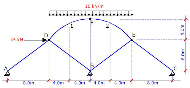
For the parabolic arch that is loaded as shown below, compute the support reactions and plot the internal stresses diagram for the identified sections. The arch is hinged at points A, B, and C.

three-hinged arch structure

SOLUTION
Geometrical properties of the arch
The ordinate (y) at any point along a parabolic arch is given by;

y = [4yc (Lxx2)] / L2
Where;
yc = Height of the crown of the arch from the base
L = Length of arch
x = Horizontal ordinate of interest
Hence, y = [4 × 10 (45xx2)] / 452

The general equation of the arch now becomes;
y = (8/9)x – (8/405)x2 —————– (1)

Differentiating equation (1) with respect to x
dy/dx = y’ = (8/9) – (16/405)x —————— (2)

From trigonometric relations, we can verify that;
Sin θ = y’/[1 + (y’)2]0.5 —————- (3)
Cos θ = 1/[1+ (y’)2]0.5 —————- (4)

From the above relations, we can carry out the calculations for obtaining the geometrical properties of the arch structure.

Let us consider point A (support A of the structure);

We can verify that at point A, x = 0, and y = 0;
From equation (2) above, y’ = 8/9;
Thus,
Sin θ = (8/9)/[1 + (8/9)2]0.5 = 0.664
Cos θ = 1/[1 + (8/9)2]0.5 = 0.747

Similarly, let us consider point 3 of the structure;

At point 3, x = 27.5m
From equation (1), we can obtain the value of y as; y = [(8/9) × 27.5] – [(8/405) × 27.52] = 9.5061m;
The tangent at that point can be obtained from from equation (2); dy/dx = y’ = (8/9) – [(16/405) × 27.5] = – 0.1975
Thus,
Sin θ = (-0.1975)/[1 + (-0.1975)20.5 = -0.1937
Cos θ = 1/[1 + (-0.1975)2]0.5 = 0.9813

For the entire section, it is more convenient to set out the geometrical properties in a tabular form. See the picture below;

ARCH%2BTABLE


Support Reactions

Let ∑MB = 0; anticlockwise negative
(Ay × 45) – (12 × 22.5 × 33.75) – (25 × 10) – (15 × 6.913) = 0
Therefore, Ay = 210.36 kN

Let ∑MA = 0; clockwise negative
(By × 45) – (25 × 35) + (15 × 6.913) – (12 × 22.5 × 11.25) = 0
Therefore, By = 84.64 kN

Let ∑MCL = 0; anticlockwise negative
(Ay × 22.5) – (Ax × 10) – (12 × 22.5 × 11.25) = 0
22.5Ay – 10Ax = 3037.5 ——— (a)

Substituting, Ay = 210.36 kN into equation (a)
Hence, Ax = 169.56 kN

Let ∑MCR = 0; clockwise negative
(By × 22.5) – (Bx × 10) – (25 × 12.5) – (15 × 3.087) = 0
22.5By – 10Bx = 358.8 ——— (b)

Substituting, By = 84.64 kN into equation (b)
Hence, Bx = 154.56 kN

The%2Barch

Internal Stresses

EXEDD

Bending Moment
MA = 0 (hinged support)
M1 = (210.36 × 7.5) – (169.56 × 5.555) – (12 × 7.5 × 3.75) = 298.294 kN.m
M2 = (210.36 × 15) – (169.56 × 8.889) – (12 × 15 × 7.5) = 298.181 kN.m
MC = (210.36 × 22.5) – (169.56 × 10.000) – (12 × 22.5 × 11.25) = 0

Coming from the right hand side;

MC = (84.64 × 22.5) – (154.56 × 10) – (25 × 12.5) – (15 × 3.087) = 0
M3 = (84.64 × 17.5) – (154.56 × 9.506) – (25 × 7.5) – (15 × 2.593) = -214.442 kN.m
M4 = (84.64 × 10) – (154.56 × 6.913) = -222.073 kN.m
MB = 0 (hinged support)

Shear
Q = ∑V cosθ – ∑H sinθ

QA = (210.36 × 0.747) – (169.56 × 0.664) = 44.551 kN
Q1 = [210.36 – (12 × 7.5)] 0.860 – (169.56 × 0.509) = 17.203 kN
Q2 = [210.36 – (12 × 15)] 0.959 – (169.56 × 0.284) = -19.040 kN
QCR = [210.36 – (12 × 22.5)] 1.000 – (169.56 × 0.000) = – 59.64 kN
Q3 = [210.36 – (12 × 22.5)] 0.981 – (169.56 × – 0.193) = – 25.782 kN
Q4L = [210.36 – (12 × 22.5)] 0.897 – (169.56 × – 0.443) = – 21.618 kN
Q4R = {[210.36 – (12 × 22.5) – 25] × 0.897} – [(169.56 – 15) × (- 0.443)] = 7.452 kN
QB = (- 84.64 × 0.747) – [154.56 × (- 0.664)] = 39.402 kN

Axial
N = -∑V sinθ – ∑H cosθ

NA = (-210.36 × 0.664) – (169.56 × 0.747) = – 266.340 kN
N1 = – [210.36 – (12 × 7.5)] 0.509 – (169.56 × 0.860) = – 207.085 kN
N2 = – [210.36 – (12 × 15)] 0.284 – (169.56 × 0.959) = -171.230 kN
NC = – [210.36 – (12 × 22.5)] 0.000 – (169.56 × 1.000) = -169.560 kN
N3 = -{[210.36 – (12 × 22.5)] × – 0.193} – (169.56 × 0.981) = -177.849 kN
N4L = -{[210.36 – (12 × 22.5)] × – 0.443} – (169.56 × 0.897) = – 178.516 kN
N4R = -{[210.36 – (12 × 22.5) – 25] × – 0.443} – [(169.56 – 15) × (0.897)] = – 176.136 kN
NA = – (-84.64 × – 0.664) – (154.56 × 0.747) = – 171.657 kN

Internal Stresses Diagram (Not to scale)

BM
Q
N

Like us on www.facebook.com/structville

Thank you for visiting.

Deflection of Statically Indeterminate Frames

The deflection of statically indeterminate frames can occur under the action of externally applied loads, temperature difference, or differential settlement of support. These deformations are often expressed in the form of deflections (translations) and rotations (slope). The knowledge about the deformation of structures is very important in that we normally verify the serviceability limit state of structures through them. By being able to limit the deflections in a building, we can make the appearance pleasant, and protect the supported partitions and finishes from cracking.

The definition of slope and deflection is represented in the picture below, showing a simply supported beam deflecting under the action of a concentrated load P.

SLOPE%2BAND%2BDEFLECTION

One of the methods of computing the deflection of statically indeterminate frames is the force method (virtual work method). In this approach, the frame is analysed using the force method, and the bending moment diagram due to the externally applied load obtained. Furthermore, a unit virtual load is placed on the basic system of the structure at the point where the deflection is sought, and analysed to also obtain the bending moment diagram. Using Verecschagin’s rule, it is possible to combine the bending moment diagram from the externally applied load with the moment diagram due to the virtual load to obtain the deflection at that point.

To learn how to apply force method to the analysis of indeterminate frames, click HERE
To learn about Vereshchagin’s rule, click HERE

In this post, we are going to calculate the vertical deflection at point B of the frame loaded as shown below. A little consideration will show that the frame is indeterminate to the 3rd order. See previous posts on how to verify the determinacy of structures. Take EI = Constant

question

(1) Step 1
Reduce the structure to a basic system. A basic system is a system that is statically determinate and stable. The adopted basic system is as shown below;

basic%2Bsystem

(2) Step 2
Replace the support reactions with unit loads and analyse each load case independently. Furthermore, plot the bending moment due to the individual virtual loads. These diagrams can be plotted without finding support reactions. The different load cases and their corresponding bending moment diagrams are shown below;

CASE 1 

case%2B1

CASE 2

case%2B2

CASE 3

case%2B3

(3) Step 3

Place the external load on the basic system, and plot the bending moment diagram.

basic%2Bsys%2Bload
basic%2Bsys%2Bbmd

(4) Step 4
Combine the various bending moment diagrams using the Verecschagin’s rule, and obtain the influence coefficients.

δ11 = Deflection at point 1 due to unit load at point 1

d11

δ11 = 1/3(3 × 3 × 5) + (3 × 3 × 6) + 1/3(5 × 5 × 5) + 1/3(3 × 3 × 3) = 119.667/EI

δ12 = δ21 Deflection at point 1 due to unit load at point 2

d12

δ12 = 1/3(3 × 4 × 5) + 1/2 [4 × (4 +10) × 6] – 1/2(5 × 5 × 10) – 1/2(3 × 3 × 10) = 66/EI

δ13 = δ31 Deflection at point 1 due to unit load at point 3

d13

δ13 = -(3 × 3 × 6) + 1/6 [5 × (22 + 6) × 5] – 1/6 [3 × (6 + 6) × 3] = 44.667/EI

δ22 = Deflection at point 2 due to unit load at point 2

d22

δ22 = 1/3(4 × 4× 5) + 1/6 [4(8 + 10) + 10(20 + 4) ] × 6 – (8 × 8× 10) = 1138.667/EI

δ23 = δ32 Deflection at point 2 due to unit load at point 3

d23

δ23 = – 1/2 [3 × (4 +10) × 6] – 1/2 [10 × (11 + 3) × 8] = -686/EI

δ33 = Deflection at point 3 due to unit load at point 3

d33

δ33 = 1/3(3 × 3× 3) + (3 × 3× 6) + 1/6 [11(22 + 3) + 3(6 + 11) ] × 8 = -497.667/EI

δ10 = Deflection at point 1 due to externally applied load

d10

δ10 = 1/3(160 × 8) × 3 = -1280/EI

δ20 = Deflection at point 2 due to externally applied load

d20

δ20 = 1/3(160 × 8 × 10 ) = -128/EI

δ30 = Deflection at point 3 due to externally applied load

d30

δ30 = 1/12 [160 × (33 + 3) × 8] = – 384/EI

(5) Step 5
Insert the influence coefficients into the appropriate canonical equation and solve for X1, X2, and X3 which are the support reactions at the points where they are required.

119.667X1 + 66X2 + 44.667X3 = 1280
66X1 + 1138.667X2 – 686X3 = – 4266.667
44.667X1 – 686X2 + 497.667X3 = 3840

On solving;
X1 = 8.196 kN;
X2 = -0.09887 kN;
X3 = 6.844 kN

(6) Step 6
Obtain the final bending moment values and plot the diagram

Final Moments

Mi = M0 + M1X1 + M2X2 + M3X3

MA = -160 + (8.196 × 5) – (-0.09887 × 10) + (6.844 × 11) = -42.7473 kNm
MB = (8.196 ×- 3) – (-0.09887 × 10) + (6.844 × 3) = -3.0673 kNm
MCB = (8.196 ×- 3) – (-0.09887 × 4) + (6.844 × 3) = -3.660 kNm
MCL = (8.196 × 3) + (-0.09887 × 4) =24.19252 kNm
MCR = (6.844 × 3) = 20.532 kNm

The final bending moment diagram is shown below.

fbmd

(7) Step 7
Place a unit vertical load at point B of the basic system and plot the bending moment diagram

def%2Bload
bas

(8) Step 8
Combine the resulting bending moment diagram with the final moment diagram form the externally applied load to obtain the deflection at point B. However, you should know that the complex bending moment on our final bending moment diagram can actually be split as shown below;

split

The subsequent combination to obtain the vertical deflection at point B is as shown below;

Deflection of statically indeterminate frames

Therefore, the vertical deflection at point B;
δB = 1/3(42.747 × 8 × 8) – 1/3(40 × 8 × 8) + 1/6(3.067 × 8 × 8) = 91.318/EI metres

Thank you for visiting, and God bless you.

Like us on www.facebook.com/structville

Blast Resistant Structures: 21 Things You Should Know

Explosives continue to be the terrorist’s preferred weapon, since they are destructive, relatively easy to obtain or fabricate, and still comparatively easy to move surreptitiously on the ground and by sea. Terrorists are also well aware that explosives produce fear in the general population far beyond the geographical location of their intended target.

time bomb explosive 3d model low poly

On the 26th of August, 2011, a car bomb attacked the UN Building in Abuja, the capital of Nigeria, after breaking through two security barriers. The attack claimed about 21 lives, and wounded about 60. A wing of the building collapsed, and the ground floor was severely damaged.

54842747 img00124 20110826 1057 1 1

There seems to be a sense of anxiety about the vulnerability of our buildings, bridges, tunnels, and utilities in the midst of numerous recognized international social and political instabilities, and given the potential for domestic groups and individuals to seek influence and create disruption by resorting to violent means. As a result, consultants designing buildings may be expected to provide advice and sometimes specific enhancements in response to quantifiable threats, as well as perceived vulnerabilities.

This post explains 21 basic things you should know about the design of blast resistant structures.

(1) An explosion is a violent thermochemical event

Explosion Image by US Department of Defense

It involves supersonic detonation of an explosive material, violently expanding hot gases, and radiation of a shock front that has peak pressures that their magnitude is higher than those that buildings normally experience under any other loadings.

(2) Building an effective security and risk assessment team

Engineers1

A comprehensive risk assessment for blast-protection design involves close collaboration among city planners, architects, engineers, blast consultant subject matter experts, and law enforcement security professionals. In this group effort, collaborating professionals assess and select the security measures needed to detect, deter, prevent, defeat, mitigate, or recover from terrorists’ bomb attacks.

(3) Nature of blast impact

blast%2Bwave

When the shock front radiating from a detonation strikes a building component, it is instantaneously reflected. This impact with a structure imparts momentum to exterior components of the building. The associated kinetic energy of the moving components must be absorbed or dissipated in order for them to survive. Generally, this is achieved by converting the kinetic energy of the moving facade component to strain energy in resisting elements.

(4) Mmmm… Not the whole structure may collapse

CihP92jXAAEVGZY 1463343433781 1316043 ver1.0%25281%2529

Structures as a whole generally are not pushed over by a common explosion. The overall mass of a structure is usually large enough to keep the kinetic energy imparted to the structure as a whole small enough that it can be absorbed by the multiple elements that would need to fail before the building topples.

(5) Stand-off distance (assumed location of explosion) is very important during assessment

transit security design fig6 1

Distance is the single most important asset to a structural engineer designing for blast resistance. The farther the explosion is from the structure, the lower are the effects that the structure must resist. Further, there often is merit to the construction of blast walls or line-of-sight barriers to add protection to a facility.

(6) Keep it confidential

M Id 355976 prevent confidential data

When blast-resistant designs are for the security and safety of a facility/building in response to a threat of a malevolent attack, information about the assumed size and location of an explosion should be kept confidential. This information could be useful to an aggressor because it can reveal a strategy to overwhelm the designed defenses.

(7) Facades and fenestration can turn to missiles

Feb Multi Fenestration 1

The catastrophic fracturing of building materials such as facades, windows, glazing, and leakage of pressure in response to a blast often can be destructive to the interiors of buildings, even when the facades of those buildings are designed to resist the effects of an explosion. These can turn to missiles and occupant injuries are very possible should the design base explosion occur. Except when the most restrictive approaches to blast-resistant design are employed (e.g., with elastic response, so a building can remain functional). Airborne glass fragmentation continues to be identified as one of the most lethal aspects of building component responses to explosive events.

(8) Mass of a building and occupancy load can be beneficial

structural loads

Blast effects usually are impulsive, meaning that they impart velocity to objects through development of momentum. With momentum being proportional to the product of mass and velocity, and kinetic energy being proportional to the product of mass and velocity squared, the larger the mass, the smaller the velocity and, hence, the smaller the energy that must be dissipated through strain. Therefore, additional mass to a building can be beneficial during an explosion.

(9) Provision for column failure and redistribution of stresses

main qimg 64a2f997363e48efe3a163414f9fbbb5 c

Consultants designing for blast often provide for the possibility that a column will be severely damaged by an explosion, in spite of our best efforts at prevention. When consultants assume that a column has lost its strength, they must develop alternative load paths to prevent a collapse from progressing from the initially damaged column through the structure. One form of alternative resistance involves making beams strong and ductile enough to span over the area of damage, thereby redistributing the load on the damaged column to adjacent columns.

(10) Emergency response considerations

cedaravefire

Designers working to enhance blast resistance must consider occupant exit and the needs of emergency responders. Blast resistance invariably includes windows with blast-resistant glass. By definition such glass is difficult to break. Firefighters will need to use special tools and engage unusual tactics to fight a fire in a building that is difficult to enter and vent, and that has features that inhibit extraction of trapped occupants. Designers might need to compensate for blast-resistance features, or enhance fire resistance.

(11) Magnitude of design pressure

Figure 1 Typical blast wave pressure time history

Designers need to understand that the magnitudes of the pressures that an explosion imparts to a structure are highly dependent on the nature of the explosive material, the shape and casing of the device, the size and range of the explosion, the angle of incidence between the advancing shock front and the impacted surface, the presence of nearby surfaces that restrict the expansion of hot gases or that reflect pressure fronts, and the robustness of the impacted surface itself.

(12) Extensive damage of structures during a blast

article 2254644 16AE711D000005DC

In many explosions that cause extensive destruction, the damage develops in two phases:
(i) the energy released by the explosion degrades or destroys important structural elements, and
(ii) the damaged structure is unable to resist gravity and collapses beyond the area of initial damage.

(13) Individual elements are often treated as nonlinear SDOF elements

SDOF plot

It is common in blast-resistant design to treat individual elements as single degree-of-freedom nonlinear systems. Performance is judged by comparison of response to limiting ductility factors (i.e., the ratio of peak displacement to displacement at yield) or support rotations, with the response calculated as though the structural element were subjected to a pressure function while isolated from other structural influences.

(14) Column integrity is the key

3328657136 6071b94b17 b

Typically, columns are the component whose integrity is key to sustaining the capability of a building’s structural system to survive a blast load. As such, attention to ensuring their survival should have the highest priority when the blast resistance of a building is to be upgraded.

(15) Beware of fragmentation

Injury and structural damage during an explosion may result not only from the direct pressure and impulse of an air blast, but also from the impact of flying objects called debris and fragmentation. Military weapons are typically explosive charges with some type of metal casing. Upon detonation, this case is ruptured and expelled as fragmentation at high velocity. Similarly, terrorist devices may be embedded with objects such as ball bearings or nails that will be ejected at high velocity. Other fragmentation may occur as objects interact with the blast wave created from a detonation and become airborne.

(16) Blast design is different from seismic design

small

The conventional approach to blast design is similar to that for seismic design, in two important ways:

(i) both loadings clearly are dynamic and, hence, solutions are energy-based, and

(ii) the way we detail structural elements determines the effective loads for which structures must be designed (meaning, we limit the strength we need to supply by allowing post-elastic behavior to dissipate energy).

However, blast loading, with its extremely fast rise time and usually short duration, is either dynamic or impulsive, depending on the nature of the explosive, its distance from the subject structure, and the level of confinement that the structure creates for the expanding hot gases.

(17) You may have to tolerate more damage

core promo

While we tolerate some damage in earthquakes, to dissipate energy, we usually allow more damage for blast events. We expect facades to sustain severe damage. In fact, blast-resistant design often tolerates breaching of the building enclosure (with attendant risk of fatalities) and even sometimes partial collapse of buildings.

(18) Reversal of stresses on floor slabs

Achieve Design Objectives

Blast-related upward impulses on floor slabs can reverse force distributions in these structural elements. In systems that are not strong and ductile enough for these reversed forces, blast-induced deflection can fracture structural elements that are required to resist gravity loads. Hence, floor systems can fail after the direct effects of the blast pass and the slab falls back downward under the influence of gravity.

(19) Consider the effectiveness of post-event evacuation functions

nigeria bomb 01

While the immediate devastating effects of explosive events can be limited by protective design strategies, post-event evacuation functions and the subsequent activities of rescue and recovery are dependent upon the integrity of stairs, vertical transportation systems, power, lighting, voice communication, smoke management, and other systems. These systems can be placed out of service throughout the building or suffer disproportionate damage if they are not specifically designed in response to the project design basis explosive threats.

(20) Engage only licensed and experienced professionals

Licensing

Blast resistance designers must be licensed design professionals who are knowledgeable in the principles of structural dynamics and experienced with their proper application in predicting the response of elements and systems to the types of loadings that result from an explosion, or they must work under the direct supervision of licensed professionals with appropriate training and experience.

(21) Threat Elimination remains the overall best option

bomb detector fraud iraqi forces

Finally, elimination of the explosive event threat and the reduction of building materials and contents that have the opportunity to participate as fuel sources in the fire development triad of oxygen, fuel load, and an ignition source remains the most attractive, competent, and cost-effective process in developing designs for facilities on any site. However, based on the threat assessment, it may be unreasonable to assume that the facility will not be exposed to explosive event effects.

Disclaimer:
I do not claim ownership to the pictures used in this post. All pictures used here belong to their respective owners, of which it is a little bit impractical to recognise them all.

Information for this article is extracted from: Donald O. Dusenberry (2010): Handbook for Blast-Resistance Design of Buildings. John Wiley and Sons Inc.
 
Thank you for visiting, and may we remain determined in our struggle to make the world free from hatred, discrimination, violence, terrorism, poverty, and crime. God bless you as you discuss and share.

Your friend,
Ubani Obinna Ranks

Application of Finite Difference Method to the Elastic Analysis of Simply Supported Thin Plates

A plate is a structure whose thickness is comparatively smaller compared to its lateral dimensions. A typical example of a plate is the floor slab commonly found in our buildings. Other examples that you can think of are sheets of steel, the panes of glass windows in your homes, or even sheets of plywood. A typical concrete plate is shown in the picture below. In this post, we are interested in the linear analysis of isotropic and homogeneous plates.

plate

Plates are used as structural members to support and transmit loads and as such, they can be subjected to bending moment, shear force, axial force, and twisting moments. The load-carrying action of a plate is similar, to a certain extent, to that of beams or cables and therefore, plates can be approximated by a gridwork of an infinite number of beams, or by a network of an infinite number of cables, depending on the flexural rigidity of the structure (Ventsel and Krauthammer, 2001).

Plates generally behave like two-dimensional structures. By implication, the loads applied on a plate are carried in two directions, and given the significant twisting rigidity of plates, a plate is stiffer than a beam of comparable span and thickness (Ventsel and Krauthammer, 2001). This two-dimensional structural action of plates results in lighter structures, and therefore offers numerous economic advantages. The bending properties of a plate depend greatly on its thickness than on any of its dimensions (Timoshenko and Woinowsky-Krieger, 1987).

Plates deform when loaded. If the deflections of a plate are small compared to its thickness, then the ‘small deformation theory’ applies, which makes the following assumptions:

1.There are no stresses in the middle plane of the plate. Hence, there are no stresses in the neutral axis during bending.
2.The points that are lying perpendicularly to the middle plane before bending remain perpendicular to the middle plane after bending.
3.The normal stresses in the transverse direction can be neglected.

By following these assumptions, the stresses on the plates can be expressed as a function of the deflection of the plate w, which is a function of the two coordinates (x,y) of the plate (Timoshenko and Woinowsky-Krieger, 1987). The governing differential equation for the deflection of thin plate under pure bending is based on the biharmonic equation shown below;

EQUATION%2B1

Before now, the common methods of analysis of thin plates have been the tedious classical solution using either the trigonometric or double series solution (Aginam et al, 2012). These days, numerical methods like Finite Element Method, Boundary Element Method, Finite Strip Method, Gridwork Method, Finite Difference Method, etc have become very popular due to their very easy modelling and programming into computer software.

However, finite element analysis is more prominent. In this article, the application of the finite difference method to the pure bending analysis of a thin plate simply supported on all sides has been presented. The result obtained has been compared with the results from other types of solutions.

Finite Difference Method of Analysis of Thin Plates

The finite difference method is a numerical solution to partial differential equations. When we have a function of two real variables f(x,y) that satisfies a given differential equation, we can evaluate f(x,y) numerically by laying a rectangular grid over the domain, and evaluate f(x,y) at the nodes – the points where the lines of the x-axis and y-axis intersect (For basic introduction you can see, Advanced Engineering Mathematics, Stroud and Booth, 2003).

Consider the 2-D network shown below

FDMMM

Let the vertical spacing of the grid be h, and the horizontal spacing be k.
From our knowledge of numerical approximation of derivatives using Taylor series expansion;

∂w/∂x = (Δx.w)/2h = (wb – wa)/2h = 1/2h [w (x + h, y) – w(x – h, y)]
∂w/∂y = (Δy.w)/2k = (wd – wg)/2k = 1/2k [w(x, y + k) – w(x, y – k)]

Analogously, for higher-order differentials;
2/∂x2 = ∂/∂x (∂w/∂x) = (Δx2 w)/h2 = (wb – 2w 0 – wa)/h2 = 1/h2 [w(x+h, y) – 2w(x,y) + w(x-h, y)]
2/∂y2 = ∂/∂y (∂w/∂y) = (Δy2 w)/k2 = (wd – 2w0 – wg)/k2 = 1/h2 [w(x, y + k) – 2w(x, y) + w(x, y – k)]

For the pure bending biharmonic equation;
(∂4 w)/∂x4 + (2∂4 w)/(∂x2 ∂y2 ) + (∂4 w)/∂y4 = P(x,y)/D, we have;

(20w0 ) – 8(wa + wb + wd + wg) + 2(wc + we + wf ) + wh ) + 1.0(wi +wj + wk + wl )= (P0 α4)/D

These expressions are often represented as patterns or computational molecules for the easy computation of the numerical solutions. The biharmonic equation pattern for computing the displacement at the interior nodes are as shown as below.

New%2BPicture
hnotk

Support Conditions
For simply supported and fixed supports, we know that the deflection at those points is equal to zero. In order to formulate the boundary conditions, let us consider the interior point 0 in the figure below.

FDMMM

You should know that at that interior point, the biharmonic equation holds true. Let us assume that points a, c, f constitutes the boundary of the plate that is simply supported, and let node i represent a fictitious node created outside the plate boundary. A little consideration will show that for wa to be zero, we have to eliminate the deflection wi, obtained by the continuation of the network beyond the boundary of the plate. This is easily done by setting w0 = -wi for simply supported plates (See David Johnson, Advanced Structural Mechanics, 2000).

Solved Example
Let us show how the finite difference method can be applied in the analysis of thin plates subjected to uniform lateral pressure of 5 kN/m2. The plate is square with dimensions of 6m x 6m and simply supported on all sides. The data of the plate is as shown below;

The plate has been represented with gridlines that have 6 divisions on all the planar dimensions. Therefore, h = k = 1.0. This shows that the gridline aspect ratio (α) = 1.0. The gridlines have been extended by fictitious nodes, in order to capture the boundary conditions. The nodes have been numbered, and all the points where the deflections are expected to be the same due to the symmetry of the plate and the loading condition have been given the same numbering.

By implication, we have seven distinguished nodes, hence, we are going to solve a 7 x 7 matrix, which can be readily solved using Microsoft Excel or MATLAB. The computational molecule (biharmonic operator/pattern) used is the one shown below. We place the computational molecule node by node and generate the appropriate equation for each node. After the equations are generated, they are arranged as appropriate and solved. The results obtained from this method have been compared with the results from the classical solution and finite element analysis.

grid

Since h = k, the representative computational molecule is given below;

New%2BPicture

P(x,y)/D = (P0 α4)/D
D = (Eh3) / [12(1- v2)] = (21.7 × 106 × 0.123) / [12(1 – 0.22)] = 37497.6/11.52 = 3255 kN/m2
(P0 h4)/D= (5 × 1.04/3255= 0.001536098

Node 1
20w1 – 8(4w2) + 2(4w4) + 1(4w3) = 0.001536098

Node 2
20w2 – 8(2w4 + w1 + w3) + 2(2w2 + 2w5) + 1(2w7 + w2 + 0) = 0.001536098

Node 3
20w3 – 8(2w5 + w2 + 0) + 2(2w4 + 0) + 1(2w6 + w1 + w3) = 0.001536098

Node 4
20w4 – 8(2w4 + w5 + w7) + 2(2w3 + w1 + w6) + 1(2w7 + 0 + 0) = 0.001536098

Node 5
20w5 – 8(w3 + w4 + w6) + 2(w7 + w2) + 1(w5 + w2 – w5 + 0) = 0.001536098

Node 6
20w6 – 8(w5 + w7) + 2(w4) + 1(2w3 – w6 – w6) = 0.001536098

Node 7
20w7 – 8(w3 + w4 + w6) + 2(w2 + w5) + 1(w2 + w7 – w7 + 0) = 0.001536098

Arranging in matrix form;

finite difference analysis

On solving;
w1 = 0.008059 m = 8.059mm (maximum deflection at the midspan of the plate)
w2 = 0.007062 m
w3 = 0.004202 m
w4 = 0.006192 m
w5 = 0.00369 m
w6 = 0.002211 m
w7 = 0.00369 m

On comparing with other methods;

Classical Solution from (Timoshenko and Woinowsky-Krieger, 1987, Table 8, Page 120)
Maximum deflection = 0.00406qa4/D = (0.00406 × 5 × 64)/3255 = 0.00808258 m

A little consideration will show that there is a percentage difference of 0.2917% between the answer from the classical method and FDM.

FEA result from Staad Pro (Mesh Size Division = 11 x 11)

fem

Maximum deflection is 0.008228 m
A little consideration will show that there is a percentage difference of 2.0539% between the answer from FEM and FDM.

Conclusion
We can see that the finite difference method can be a handy solution to the analysis of thin plates. The method can be easily programmed on computer software, and the method generally yields lower bound solution.

REFERENCES
(1) Aginam C.H., Chidolue C.A., Ezeagu C.A.(2012): Application OF Direct Variational Method in the Analysis of Isotropic Thin Rectangular Plates. ARPN Journal of Engineering and Applied Sciences VOL. 7, NO. 9, ISSN 1819-6608 pp 1128 – 1138
(2) David Johnson (2000): Advanced Structural Mechanics. Thomas Telford Publishing ISBN: 0 7277 2860 1
(3)Timoshenko S. and Woinowsky-Krieger S. (1987): Theory of plates and shells (2nd Edition). McGraw Hill Book Company
(4)Ventsel E., Krauthammer T. (2001): Thin Plates and Shells Theory, Analysis, and Applications. Marcel Dekker, Inc New York. ISBN: 0-8247-0575-0

To contact the author, send an e-mail to ubani@structville.com or send a Whatsapp message to +2347053638996. Please keep visiting the blog. God bless you.

Like us on www.facebook.com/structville