8.7 C
New York
Tuesday, September 17, 2024
Home Blog Page 66

Manholes: Uses, Design, and Construction

A manhole (alternatively called utility hole, cable chamber, maintenance hole, inspection chamber, access chamber or confined space) is the top opening to an underground utility vault used as an access point for making connections or performing maintenance on underground and buried utility and other services including sewers, telephone, electricity, storm drains, and gas. The types of manholes that would be discussed in this article include sanitary sewer manholes and stormwater drain manholes.

New%2BPicture%2B%252816%2529

Location of sewer manholes

Storm sewer manholes are usually provided at;

(a) Intersections of stormwater drains
(b) Junctions between different sizes of stormwater drains
(c) Where a stormwater drain changes direction/gradient
(d) On long straight lengths at the following intervals;
– For pipes with a diameter less than 600mm, provide manholes at a maximum interval of 40m
– For pipes with a diameter between 600mm – 1050mm, provide manholes at a maximum interval of 80m
– For pipes with a diameter greater than 1050mm, provide manholes at a maximum interval of 120m

In addition, manholes should wherever possible be positioned such that the disruption to the traffic will be at a minimum when their covers are lifted under normal maintenance operations.

Access opening of manholes

A manhole opening for man access should not be smaller than 550mm by 550mm. If cat ladders are installed in a manhole, the minimum clear opening should be 675mm by 675mm. A man access opening should be placed off the centreline of the stormwater drain for deep manholes, and along the centreline of the stormwater drain for shallow manholes with depths less than 1.2m.

New%2BPicture%2B%252814%2529

Covers to manholes

Manhole covers should be sufficiently strong to take the live load of the heaviest vehicle likely to pass over, and should be durable under different weather conditions. Manhole covers should not rock when initially placed in position, or develop a rock with wear.

Step irons and cat ladders

Step-irons should be securely fixed in position in manholes, and should be equally spaced and staggered about a vertical line at 300mm centres. Cat ladders should be used in manholes deeper than 4.25m or where manholes are frequently entered. It is safer and easier to go down a ladder when carrying tools or equipment.

New%2BPicture%2B%252815%2529

Forces acting on round manhole shafts

The forces acting on circular manhole shafts are;

– Lateral earth pressure
– Hydrostatic pressure

Because both loads are uniformly distributed around the periphery of the manhole, no bending moment is experienced by the manhole section. The following equation may be used to calculate the total lateral pressure at a given depth (H).

p = (Ws × H × Ks × Cosi) + (Ww × H)

Where;
p = total earth and hydrostatic pressure
Ws = Unit weight of backfill material
H = depth of manhole
Ks = coefficient of earth pressure
i = angle of internal friction of soil
Ww = unit weight of water

In theory, the pressure (P) acts equally around the periphery of the manhole section, placing the ring in pure compression without introducing bending moments into the concrete section in the horizontal plane. The compressive stress in any section of the round manhole riser is given by the equation;

S = pD/2t

Where;
S = compressive stress in the ring
p = total lateral earth and hydrostatic pressure
D = diameter of manhole
t = thickness of the manhole

manhole
conus

Example on Application of Vereshchagin’s Rule on Analysis of Frames Using Force Method

The frame shown above is supported with rollers at A, C and D, and pinned at point B. It is loaded as shown , and all columns have a cross-section of 30cm x 30cm, while the beams have a cross-section of 45cm x 30cm. Draw the bending moment diagram due to the externally applied load. Where necessary take E = 21.5 KN/mm2. In this case we are utilizing the force method, and we will apply Vereshchagin’s rule.

(1) First we reduce the structure to a basic system. A basic/primary system is a system that is statically determinate and stable. This is done by removing the vertical redundant supports at points C and D.

New%2BPicture%2B%25287%2529

(2) We draw the bending moment for case 1 (Unit load applied at support C). X1 = 1.0

New%2BPicture%2B%25288%2529

(3) We draw the bending moment for case 2 (Unit load applied at support D). X2 = 1.0

New%2BPicture%2B%25289%2529

(4) We load the basic system with externally applied load and analyse it.

New%2BPicture%2B%252810%2529

(5) We draw the bending moment diagram due to the externally applied load on the basic system.

New%2BPicture%2B%252811%2529

(7) We write our appropriate canonical equation, and compute the influence coefficients using Vereshchagin’s rule. Solve the canonical equation and obtain X1 and X2.

(8) Substitute your final values into the Mdef equation.

(9) Plot your final moment diagram.

New%2BPicture%2B%252812%2529

To download the full calculation sheet, click HERE.

Formulation of Diagram Combination Equations Using Vereschagin’s Rule

The famous Maxwell-Mohr’s integral forms the backbone of the force method of structural analysis. It is also an important and universal method of computing displacements in beams and frames. It is more ideal for hand calculation purposes than the direct stiffness method which may involve large matrices.

The Mohr’s integral may be solved by direct multiplication and integration of bending moment equations (one linearly and the other of any arbitrary form), or by using the bending moment diagram multiplication/graphical method which is based on Vereschagin’s rule. Vereschagin’s rule is the graphical solution of Maxwell-Mohr’s integral.

In the paper downloadable in this post, a lot of formulas were derived for combining different shapes of bending moment diagrams for use in the graphical method than can be found in many structural engineering textbooks.

Vereschagin%2527s%2Brule%2Bcombination%2Bdiagram

The diagram multiplication method presents the most effective way for computation of any displacement (linear, angular, mutual, etc.) of bending structures, particularly for framed structures. The advantage of this method is that the integration procedure according to Maxwell–Mohr integral is replaced by an elementary algebraic procedure on two bending moment diagrams in the actual and unit states.

This method was developed by Russian engineer Vereschagin in 1925 and is often referred to as the Vereschagin’s rule, in which the area of the bending moment diagram in the actual state multiplies the ordinate that its centroid makes with the unit state diagram in order to obtain the deformation.

READ ALSO ON THIS BLOG
Example on the Application of Vereschagin’s Rule on the Analysis of Indeterminate Frames
On the Deformation of Statically Indeterminate Frames Using Force Method

In the article, the following examples can be found;

Example 1

The procedure for the combination of the two shapes shown above is presented in the screenshot shown below;

Procedure%2Bfor%2Bcombination%2Bof%2Btrapeziums%2Busing%2BVereschagin%2527s%2Brule

Example 2

New%2BPicture%2B%25282%2529

In this case, we have to split the shapes at the point of contraflexure, so we have two shapes with areas A1 and A2 combining with the triangle below them. So as usual, we have;

SHAPE%2B2

To download the paper the full paper on equation formulation where series of shapes encountered in analysis have been combined, click HERE

To know how Vereschagin’s rule is applied in analysis, click HERE

Visit our facebook page, www.facebook.com/structville

Construction of Precast Filigran Slab | Filigree Slab

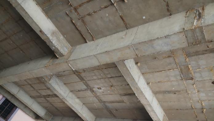
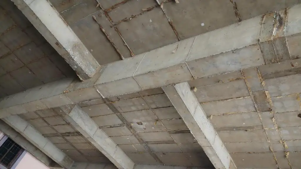
Filigran slab (also called filigree slab) is a universal system of composite reinforced concrete slab, that is used all over the world. This is due to their excellent structural solutions in the prefabricated construction method adapted to industrial, residential, and other special structures, such as bridges. Filigran slabs are prefabricated in the factory and are made up of thin reinforced concrete slabs, which are part of the complete reinforced concrete floor, and have a thickness between 40 and 75 mm.

The precast concrete panel in a filigree slab usually has a steel lattice girder system embedded within it. This lattice, typically formed from welded steel wire mesh or prefabricated trusses, acts as both a structural reinforcement and a void former. The voids can be filled with various lightweight materials like polystyrene blocks, clay pots, or even air, depending on the desired weight, thermal, and acoustic properties of the final slab.

The precast base incorporates bottom reinforcement, typically in the form of welded mesh or rebar cages. Once delivered to the construction site, the filigree slabs are erected on temporary supports. Additional top reinforcement is then placed on the slabs, followed by a concrete topping pour. This final layer creates a composite action with the precast element, resulting in a robust and efficient floor system.

See a picture of a filigree slab panel below;

finished%2Bfiligree

Technical Specifications of Filigree Slabs

Due to transportation (the maximum permissible width of a moving vehicle during transportation), the recommended width is between 0.60m to 2.50m. The maximum recommended width of each precast panel is 2.70m, and the length may be as high as 12.00m.

Transportation of precast filigree slab panels

Each filigran slab has main reinforcements in the transverse and longitudinal directions (based on applied loading and design), and lattice girder trusses spaced at not more than 750mm and placed parallel to the longer side. After they are cast and installed, the final in-situ concrete topping (not less than 120mm) is used to finish the slab to the required final design thickness.

During the industrial fabrication of precast filigran slabs, all recesses, ceiling apertures, electrical sockets etc are taken into account. The prefabricated slab acts as a shuttering (soffit formwork) during the building phase, and after the addition and hardening of the in-situ concrete, the whole system effectively becomes a single slab.

A typical complete arrangement of a filigran slab is shown in the picture below;

LABELS

Where;
(1) In-situ concrete topping/overlay
(2) Prefabricated plate
(3) Panel joint reinforcement
(4) Lattice girder trusses

See typical arrangement of reinforcements and lattice girder trusses for filigree slabs below.

Typical reinforcement arrangement for precast filigree slab
welding of lattice girder for filigree slab
Welding of lattice girder for filigree slab

In-situ Concrete Topping/Overlay

The fusion of the two layers of the concrete, (precast and monolithic cast in-situ) is done after the precast filigree slabs are installed in place. The surface of the prefabricated panels should be made rough so as to facilitate adequate bonding with the cast in-situ slab.

The steel trusses included in the panels are suitable motherboard for rigidity during lifting, transportation, and performance of the floor. The diagonals of the lattice truss girder serve to accept the thrust in the joint between the precast panel and the in-situ concrete, while the upper booms and diagonals serve to provide the stiffness necessary during assembly.

POURING CONCRETE OVERLAY ON FILIGREE SLAB
Pouring is-situ concrete topping/overlay on precast filigree slab

Work Placement of Filigran Slab

Filigree slab panels are transported to the building in accordance with draft assembly drawings. Project cost and transport cost are included in the total cost of the floor. Before installation, there is a need to prepare a support/mounting place, to place them in the required panel, and the designed level.

The necessary supports (props, joints) are indicated by the designer. The permissible moments and lateral forces are independent of the girder diameters and the assembly height of the lattice girders.

The thickness of the precast slab and the diagonal diameter of the lattice girders determine the bending capacity as well as the lateral load capacity. In addition to the net weight of the ceiling, assembly loads of 1.5 kN/m2 or 1.5 kN (under the most unfavourable conditions) are taken into account.

Unloading Filigree Slab

Filigree slab panels are generally unloaded from the truck by a building site crane. The slab weighs approximately 125 kg/m2 (standard thickness). The karabiners are hooked into the diagonals of the truss lattice girder, not into the upper boom. Stabilizing suspension gear should be used while lifting the filigree slab.

The stabilizing suspension gear of steel cables or chains should be used to guarantee equally distributed loading of the dead weight on the lattice girders. In either case, the spacing of the suspension gear from the end of the lattice slab should be approximately 1/5 of the total length of the slab.

New%2BPicture%2B%25285%2529

Reinforcing across the joints

Joint reinforcement between the slabs is guaranteed either in the form of reinforcing steel mesh or individual reinforcing rods. The dimensions of the reinforcing rods are stated in the installation plan. The joint reinforcement must go beyond the butt of the plates by at least 500 mm in the installation plan. The reinforcement prevents dowelling or uneven deformation of the individual pieces of the ceiling.

Preparation for concreting

Before the in-situ concrete is added, the following must be checked whether:

1. The slab has been laid properly. It is imperative to note that the main reinforcements are parallel to the long span in the panel, but during placement, they are placed parallel to the short span.
2. The precast slabs are supported and should be lying horizontally.
3. The edges of the slab are completely level along the entire length of the joints on the underside.
4. The reinforcement over the joints, the additional top reinforcement bars as well as services have been laid.

PIC%2B5

Design Considerations for Filigree Slabs

While offering numerous advantages, filigree slabs require careful design considerations:

  • Span Limitations: The precast elements have inherent limitations in terms of achievable spans compared to solid post-tensioned slabs.
  • Load Capacity: The design needs to account for the dead load of the precast element, superimposed dead loads (partitions, finishes), live loads (occupancy), and any additional loads.
  • Deflection Control: The design must ensure that the deflections of the completed floor system stay within acceptable limits to prevent serviceability issues.
  • Fire Resistance Requirements: The choice of precast concrete strength, void fillers, and top concrete thickness needs to meet the building’s fire resistance rating.
  • Service Integration: The layout of voids must be carefully planned to accommodate necessary building services without compromising structural integrity.
  • Transportation and Handling: The weight and dimensions of precast elements need to comply with transportation regulations and on-site handling limitations.

Advantages of Filigree Slab

Filigree slabs offer a multitude of benefits compared to traditional cast-in-place concrete slabs or other precast options:

1. High accuracy and smoothness of the floor eliminate the need for plastering.
2. The strength of plates adapts to the individual changes, in accordance with the terms of use of the ceiling.
3. The production of the plate for the construction requires minimum formwork.
4. Simple and short construction period
5. Reduction in the number of workers needed for the preparation of the floor.
6. Filigran slab saves materials costs and labour charges for scaffolding and formwork.
7. Filigree slabs are lightweight and easy to handle and fix.
8. Recesses for electrical and plumbing installations are made at the pre-production stage itself.

Like our Facebook page on www.facebook.com/structville

You can find out why this soak-away excavation collapsed..

This soak-away was being constructed somewhere in Abuja when some part of the soil caved in, and caused considerable damage to the already laid reinforcement. Fortunately no life was lost, but this led to serious cost consequences and delay in the project completion time.See the soak-away/septic tank before it collapsed at the picture below.

standing

In Nigeria, tropical laterites are predominant and forms the subsoil of most areas. Most laterites are cohesive-frictional soils which means that they possess both angle of internal friction and cohesion. Unlike sands, these soils are self supporting to a certain depth during excavation called the CRITICAL DEPTH, and this is mainly due to their cohesive properties. In cohesive soils, when the critical depth of excavation is reached, the sides of the cut will fail and the soil mass will fall to the bottom. Unlike sands (frictional/granular materials), the steepest slope at which a cohesive soil will stand decreases as the depth of excavation increases.

The pressure diagram for frictional-cohesive soils based on modified Rankine’s theory is as shown below;

COUNTERFORT%2BWALLS

Where;

45678

The values of the cohesion and angle of internal friction of a soil sample can be obtained by carrying out very quick unconsolidated undrained triaxial test in the laboratory on an ‘undisturbed’ sample collected from the site of excavation. So you can carry out quick calculation to determine the critical depth using the formular above. Since the net pressure over the critical depth (2Zo) is zero, the cohesive soil should be able to stand unsupported up to this depth.

However to increase the stability of cuts in excavations, you can do the following;
(1) Alter the slope of the cut
(2) Use soil nailing
(3) Brace the excavation
(4) Use tie-back systems

If these considerations were made initially, the construction wold not have suffered such setback.

Design of Continuous Slab and Beam Strip Footing

Continuous beam and slab strip footings normally consist of inverted T-beams that are used to support a series of columns or continuous walls. They are a cheaper alternative to raft foundations and can be used where individual pad foundations will overlap or where the soil is expected to undergo differential settlement or excessive shrinkage and swelling. The design of a continuous beam and slab strip footing involves the design of the base slab and upstand beam by providing adequate concrete sections and reinforcements to resist the earth pressure reaction from the applied load.

Continuous Slab and Beam Strip Footing

The design presented here is an excerpt from my final year project ‘Structural Analysis and Design of 35,000 Capacity Reinforced Concrete Stadium’. After the analysis and design of the superstructure (see a section of the stadium in the picture below), it was realized that a very large magnitude of axial loads and moments are being transferred to the foundation.

Foundations must be designed to resist geotechnical and structural failure, and at the same time should be economical. The ultimate bearing capacity of the supporting soil at 2.00m depth was very good at 380 KN/m2 (gravely sand), so a shallow foundation was adopted.

SECTION

However, adopting a pad footing proved very uneconomical given the large area of excavation required (columns are spaced at 6.0m), and the depth of concrete needed to handle shear forces was much. Raft foundation proved to be too expensive for soil with such a good bearing capacity.

After much consideration, it was realized that chaining the columns continuously will do the trick, but at the same time, it is possible to combine the slab with upstand beams running continuously along the axis of the column. The whole aim was to reduce the great quantity of concrete that would have been required to control diagonal shear by using shear reinforcements (stirrups) in the beams. This eventually proved to be much cheaper.

New%2BPicture

In the excerpts of the design presented below, the following data were used;

Concrete grade = 30 N/mm2
Yield strength of reinforcement = 460 N/mm2
Concrete cover of reinforcement = 50mm
Bearing capacity of soil = 380 kN/m2

For this post, let us consider an axis from the structure in which the intermediate columns approximately have equal ultimate axial loads of 3081.075 kN while the end columns have an axial load of 1680.3 kN (see Figure below).

New%2BPicture%2B%25281%2529

From the symmetrical arrangement of the loads, it is quite obvious that the centroid will pass through the middle column, hence, soil pressure can be assumed to be uniform under the whole length of the footing.

Dimension of all columns = (500 x 300 mm)
Total Ultimate Limit State (ULS) Load = 2(1680.3) + 5(3081.075) = 18765.975 kN
Axial load conversion factor to Serviceability Limit State (SLS) α = 1.45
NSLS = 18765.975/(1.45 ) = 12942.05 kN

Assume 12% of service load to be the self-weight (SW) of the footing
SW = (12/100) × 12942.05 = 1553.04 kN
Area of footing required Areq = NSLS+ SW /(Bearing Capacity) = (12942.05 + 1553.04)/380 = 38.14 m2

Taking a 36.3m long base, the width B = 38.14/36.3 = 1.051 m
Therefore, provide a 1.1 m x 36.3m base (Aprov = 39.93 m2)
Let the thickness of the footing be 1100mm
Earth Pressure intensity (q) = N/Aprov = (18765.975 KN)/(39.93 m2 ) = 469.97 kN/m2

Design of the footing cantilever slab portion (per meter strip)
Note that the bending moment in the slab is maximum at the face of the column (in this case at the face of the upstand beams)

Width of the upstand beam = 500mm = 0.5m

Hence, Moment arm (jxx) = (1.1– 0.5)/(2 ) = 0.30 m
Assume depth of slab h = 300mm, concrete cover (Cc) = 50mm and assuming that (ϕ) Y20mm bars will be used;
Hence, the effective depth (d) = h – Cc – ϕ/2 = 300 – 50 – (20/2) = 240mm

Mx-x = (q × jxx2) / 2 = (469.97 × 0.32)/2 = 21.14 KN.m
k = M/(Fcubd2 ) = (21.14 × 10⁶) / (30 × 1000 × 2402 ) = 0.012
k < 0.156, no compression steel needed
Lever arm (la) = 0.5 + (0.25 – K/0.9)0.5 Hence la = 0.95

The area of tenseion steel required; ASreq = M/(0.95fy.la.d ) = (21.14 × 10⁶) / (0.95 × 460 × 0.95 × 240) = 212.17 mm2

ASmin = 0.13bh/100 = (0.13 × 1000 × 300)/100 = 390 mm2
Therefore, Provide Y12 @ 200 mm c/c (Asprov = 566 mm2/m)

Distribution bars on slab
ASmin = 0.13bh/100 = (0.13 × 1000 × 300)/100 = 390 mm2
Therefore, Provide Y12 @ 250 mm c/c (Asprov = 452 mm2/m)

Shear design of slab
The concrete resistance shear stress (Vc) = 0.632 × (100As/bd)1/3 × (400/d)1/4
Vc = 0.632 × [(100 × 566)/(1000 × 240)]1/3 × (400/240)1/4
Vc = 0.632 × 0.617 × 1.136 = 0.443 N/mm2
For Fcu = 30N/mm2
Vc = 0.443 × (30/25)1/3 = 0.470 N/mm2

Critical diagonal shear force at ‘d’ from the face of support (Q)
Q = q (jxx – d)
Therefore the shear force Q= 467.97 × (0.30 – 0.24) = 28.078 KN/m
The resultant shear stress V = (28.078 × 10³)/(1000 × 240) = 0.1169 N/mm2
We can see that V < Vc, ie (0.1169 N/mm2 < 0.470 N/mm2)
Hence, diagonal Shear is ok
A little consideration will show that punching shear at 1.5d from the face of column is also ok (falls outside the footing dimensions). Hence design is ok.


Design of ground longitudinal upstand beam

Width of beam = width of column = 500mm = 0.5m
Uniformly distributed soil reaction on beam = Earth pressure intensity × Width of footing = 467.97 x 1.1 = 514.77 KN/m

New%2BPicture%2B%25282%2529
New%2BPicture%2B%25283%2529

Bottom Reinforcement Design (Column Support Points)
Total depth of beam = 1100mm
Effective depth (d) = 1100 – 50 – 16 – 10 = 1024mm (assuming the use of Y32mm bars and Y10mm links)

Design Moment (M) = 1960.09 kN.m
k = M/(Fcubd2 ) = (1960.09 × 106)/(30 × 500 × 10242) = 0.124

Since k < 0.156, no compression steel needed
Hence the lever arm, la = 0.5 + (0.25 – K/0.9)0.5 Hence la = 0.834

The area of tension steel required; ASreq = M/(0.95Fy.la.d ) = (1960.09 × 106)/(0.95 × 460 × 0.834 × 1024) = 5252 mm2
ASmin = 0.26bh/100 = (0.26 × 500 × 1100)/100 = 1430 mm2
Provide 6Y32mm + 2Y25mm BOT (Asprov = 5806 mm2) around the penultimate supports. (See detailed drawings)

Central Column Support Bottom Reinforcement Design
M = 1603.71 kN.m
k = M/(Fcubd2) = (1603.71 × 106) / (30 × 500 × 10242) = 0.1019, k < 0.156, no compression steel needed.
la = 0.5 + (0.25 – K/0.9)0.5 Hence la = 0.869

The area of tension steel required; ASreq = M/(0.95Fy.la.d ) = (1603.71 × 106)/(0.95 × 460 × 0.869 × 1024) = 4124 mm2
ASmin = 0.26bh/100 = (0.26 × 500 × 1100)/100 = 1430 mm2
Provide 4Y32mm + 3Y25mm (Asprov = 4689 mm2) at the central column support. (See detailed drawings)

Top Reinforcement Design (Beam Span Design)
M = 1440.08 kN.m
k = M/(Fcubd2) = (1440.08 × 106/(30 × 500 × 10242) = 0.0916
la = 0.5 + (0.25 – K/0.9)0.5 Hence la = 0.885
The area of tension steel required; ASreq = M/(0.95Fy.la.d ) = (1440.08 × 106)/(0.95 × 460 × 0.885 × 1024) = 3387.5 mm2
ASmin = 0.18bh/100 = (0.18 × 500 × 1100)/100 = 990 mm2
Provide 4Y32mm + 2Y16mm (Asprov = 3618 mm2)

Mid-span Sections Design
M = 802.71 kN.m
k = M/(Fcubd2)) = (802.71 × 10⁶)/(30 × 500 × 10242) = 0.051; k < 0.156, no compression steel needed
la = 0.5 + (0.25 – k/0.9)0.5 Hence la = 0.939

The area of tension steel required; ASreq = M/(0.95Fy.la.d ) = (802.71 × 10⁶)/(0.95 × 460 × 0.939 × 1024) = 1910 mm2
ASmin = 0.18bh/100 = (0.18 × 500 × 1100)/100 = 990 mm2
Provide 4Y25mm + 2Y16mm (Asprov = 2366 mm2)

Longitudinal Face Side Bars
Provide Y16mm @ 200mm c/c both faces

Shear design of the longitudinal ground beams

Punching Shear at column face
Taking the maximum shear force for punching shear verification at column face
Punching shear at column face Vf = (1870 × 3.4846)/3.6346 = 1792.8 kN
Punching shear stress = (1792.8 × 1000)/(500 × 1024) = 3.5016 N/mm2
We can see that 3.5016 N/mm2 < 0.8√fcu < 5 N/mm2
Therefore, the depth of the section is adequate for shear.

Maximum shear force on the footing = 1870.99 kN
The shear force at ‘d’ from the face of the column, Vd = (1870.99 × 2.4606)/3.6346 = 1266.64 kN (calculation was done looking at the shear force diagram)
The shear stress v = Vd/bd = (1266.64 × 1000)/(500 × 1024) = 2.474 N/mm2

The concrete resistance shear stress (Vc) = 0.632 × (100As/bd)1/3 × (400/d)1/4
Hence, Vc = 0.632 × [(100 × 5806)/(500 × 1024)]1/3 × (400/1024)1/4
Vc = 0.632 × 1.032 × 1 = 0.652 N/mm2
For Fcu = 30 N/mm2, Vc = 0.652 × (30/25)1/3 = 0.692 N/mm2

Hence shear reinforcement is required
Trying 4 legs of Y10mm, we have;
Spacing Sv = (0.95 × Fyv × Asv)/(bv (v – Vc)) = (0.95 × 460 × 314)/(500 (2.474 – 0.692)) = 154 mm
Maximum spacing = 0.75d = 0.75 × 1024 mm = 768 mm
Provide 4Y10mm @ 150mm c/c links as shear reinforcement

The extent of shear links
Shear stress of nominal links Vn = [(Asv/Sv) × 0.95fy + (bw × Vc)] d
Concrete Resistance shear stress Vc = 0.692 N/mm2
Vn = [(236/300) × 0.95 × 460 + 500 × 0.692) × 1024 × 10-3 = 706.326 KN (Taking a nominal shear reinforcement of 3Y10 @ 300mm)
Extent of shear links Sn = (Vd – Vn)/q + d Extent of shear links Sn = (1266.64 – 706.326)/(514.77 + 1.024) = 2.112 m
Therefore, stop main shear links(4Y10mm @ 150mm) i.e. at 2.2 m from face of column and provide nominal reinforcement of 3Y10 @ 300mm till the point of zero shear force.

Shear force at the central column support point = 1574.01 kN
The shear force at d from the face of column, Vd = (1574.01 × 1.88369)/3.05769 = 969.668 kN
The shear stress v = Vd/bd = (969.668 × 1000)/(500 × 1024) = 1.893 N/mm2
The concrete resistance shear stress (Vc) = 0.632 × (100As/bd)1/3 × (400/d)1/4
Vc = 0.632 × ((100 × 4689)/(500 × 1024))1/3 × (400/1024)1/4
Vc = 0.632 × 0.9711 × 1 = 0.613 N/mm2
For Fcu = 30 N/mm2, Vc = 0.613 x (30/25)1/3 = 0.6517 N/mm2

Hence shear reinforcement is required
Trying 4 legs of Y10mm, we have;
Spacing of links Sv = (0.95 × Fyv × Asv)/(bv (v – Vc)) = (0.95 × 460 × 314)/(500(1.893 – 0.6517)) = 221.087 mm
Maximum spacing = 0.75d = 0.75 x 1024 =768 mm
Provide 4Y10mm @ 200mm c/c links as shear reinforcement

The extent of shear links
Shear stress of nominal links Vn = [(Asv/Sv) × 0.95fy + (bw × Vc)] d
Vc = 0.6517 N/mm2
Vn = [( 236/300) × 0.95 × 460 + 500 × 0.6517)] × 1024
Hence, Vn = 685.69 kN (Taking a nominal shear reinforcement of 3Y10 @ 300mm)
Extent of shear links Sn = (Vd – Vn)/q + d
Extent of shear links Sn = (698.665 – 685.69)/514.77 + 1.024 = 1.049 m
Stop shear links at 1.1 m from the face of the column and provide nominal reinforcement = 3Y10 @ 300mm
The picture below shows the section through the first span of the continuous footing;

ccccc

The picture below shows the section through the second support of the continuous footing;

vbgg

Deflection of Statically Determinate Frames | Virtual Work Method

Structures deform when subjected to various conditions such as external loads, changes in temperature, differential settlement, or fabrication errors. Structural deformation is often considered in terms of rotation (slope) or translation (deflection).

The slope is the angle (in radians) that the elastic curve makes with the original neutral axis of the member, while deflection is the movement the structural member makes from the original neutral axis. In the design of structures, it is necessary to control the deflection for aesthetics and appropriate functionality (like cracking of finishes).

Statically determinate frames will deflect under the action of externally applied load, but will not be sensitive to indirect actions such as temperature difference and differential settlement. The deflection of statically determinate frames can easily be obtained using the virtual work method. For practical analysis of normal frames, the deflection due to shear can be ignored.

In beams and frames, bending moment is the major cause of deflection, while in trusses, axial forces are the major cause of deflection. Deformation due to shear is often very small and is neglected in most simple analyses. In the solved example that is downloadable in this post, the frame shown above is completely analysed, and the horizontal deflection at point B is obtained using the virtual work method. The analysis was carried out assuming linear elastic material response. Both the integration method (Mohr’s integral) and graphical method (Vereschagin’s diagram combination method) were used in the analysis.

Bending moment, shear force, and axial force contribute to the total deformation of a frame and the formula is given by;


δi = 1/EI∫Mm ds + k/GA∫Qq ds + 1/EA∫Nn ds ——- (a)

Where;
1/EI∫Mm d= Deflection due to bending moment
k/GA∫Qq ds = Deflection due to shear force
1/EA∫Nn d = Deflection due to axial force

Of all these, the highest contributor to deflection of statically determinate frames is the bending moment. Oftentimes, deformation due to shear force and axial forces are neglected, while in some analyses, they can be quite significant. The analysis below gives an example of the computation of deformation in a frame neglecting the shear and axial forces.

Hence displacement using Mohr’s integral is given by;


δi = 1/EI∫Mm ds ————– (b)


Where;
M = Moment due to externally applied load
m = Moment due to unit load applied at the point where the displacement is sought
EI = Flexural rigidity

The steps involved in the analysis of deflection of statically determinate frames can be summarised as follows:

  1. Analyse the frame completely and draw the final bending moment diagram due to externally applied load.
  2. Remove the externally applied load, and replace it with a virtual unit load, in the direction and location that the deflection is sought. For slopes, you place a unit moment at the point you wish to obtain the rotation.
  3. Analyse the frame completely under the action of the virtual load and draw the virtual bending moment diagram.
  4. Combine the bending moment equations or diagrams of the external and virtual loads and compute the value of the deflection.

Worked Example

For the frame that is loaded as shown below;
(i) Find the support reactions
(ii) Draw the internal stresses diagram
(iii) Obtain the horizontal displacement at point B using both graphical and integration methods. (EI = Constant);

Simply supported frame

Solution
The degree of static indeterminacy is given by;
RD = (3m + r) – 3n – S
m = 3 (three members)
r = 3 (three reactions)
n = 4 (four nodes)
S = 0 (no internal hinge)

RD = 3(3) + 3 – 3(4) = 0
This shows that the structure is statically determinate and stable.

(i) Support Reactions
Let ΣMD = 0; clockwise negative
(Ay × 6) + (5 × 3) – (10 × 62/2) = 0
Ay = 27.5 kN

Let ΣMA = 0; clockwise negative
(Dy × 6) − (5 × 3) – (10 × 62/2) = 0
Dy = 32.5 kN

Let ΣFX = 0;
-Dx + 5 = 0, therefore,
Bx = 5 kN

(ii) Internal Stresses

Section 1-1 (A-1B) (0 ≤ y ≤ 3)

section 1 1

Bending Moment
My = 0 —- (1)

Shear
Qy = 0

Axial
Ny + 27.5 = 0
Ny = −27.5 kN

NA – N1B = −27.5 kN

Section 2-2 (1UP – BB) (3.0 ≤ y ≤ 6.0)

2 2

Bending Moment
My = −5(y−3)
∴ My = −5y + 15 —- (2)

At y = 3m,
M1UP = −5(3) + 15 = 0

At y = 6m
MBB = -5(6) + 15 = −15 kNm

Shear
Qy + 5 = 0
Qy = −5 kN
Q1UP – QBB = −5 kN

Axial
Ny + 27.5 = 0
Ny = −27.5 kN
NA – N1B = −27.5 kN

Section 3-3 (BR – CL) (0 ≤ x ≤ 6.0)

3 3

Mx = (27.5x) – (10 × x2/2) − (5 × 3)
Mx = −5x2 + 27.5x – 15 —– (3)

At x = 0,
MBR = −15 kNm

At x = 6m
MCL = −5(62) + 27.5(6) – 15 = −30 kNm

∂Mx/∂x = Qx = −10? + 27.5

At ∂Mx/∂x = 0, bending moment is maximum
Hence, −10x + 27.5 = 0
x = 27.5/10 = 2.75m
Hence the maximum sagging moment occurs at 2.75m

Mmax = −5(2.752) + 27.5(2.75) – 15 = 22.8125 kNm

Shear
Qx = – 10x + 27.5

At x = 0
QBR = 27.5 kN

At x = 6m
QCL = 27.5 – 10(6) = −32.5 kN

Axial
Nx + 5 = 0
Nx = −5 kN
NBR – NCL = −5 kN

Section 4-4 (D – CB) (0 ≤ y ≤ 6)

4 4

Bending Moment
My = −5y —– (4)

At y = 0,
MD = 0

At y = 6m
MCB = −5(6) = −30 kNm

Shear
Qy − 5 = 0
Qy = 5 kN
QD – QCB = +5 kN

Axial
Ny + 32.5 = 0
Ny = −32.5 kN
ND – NCB = −32.5 kN

The internal stresses diagram of the frame is shown the figure below. The sign conventions are so important because of how they influence the results we obtain for the deflections. The internal stresses equations labelled (1), (2), (3), and (4) will be used for the integration method.

Final bending moment diagram

(iii) Horizontal displacement at point B
We will now remove the externally applied load, and place a unit horizontal load at point B of the structure. We will analyse the structure as usual and obtain the bending moment equations, and plot the bending moment diagram. In this case, we will neglect the axial and shear forces.

Deflection of statically determinate frame

Support Reactions
Let ΣMD = 0; clockwise negative
(Ay × 6) + (1 × 6) = 0
Ay = −1.0

Let ΣMA = 0; clockwise negative
(Dy × 6) − (1 × 6) = 0
Dy = 1.0

Let ΣFX = 0;
−Dx + 1 = 0, therefore, Bx = 1.0

Internal Stresses due to Virtual unit Load (Bending moment only)

Section A-B (0 ≤ y ≤ 6)
My = 0 (no bending moment on the section) —- (1 & 2)

Section B-C (0 ≤ x ≤ 6)
Mx = −x ————- (c)
At x = 0, MBR = 0
At x = 6m, MCL = −6

Section D-C (0 ≤ y ≤ 6)
My = −y —————- (d)
At y = 0, MD = 0
At y = 6m, MCB = −6

The bending moment diagram due to the virtual unit load at point B is shown below;

bnm virtual load

Deflection Using Mohr’s Integral

Therefore using the integration method, we can obtain the deflection at point B integrate section by section. Note that section A – B will be zero all through because in the bending moment diagram due to the unit load, there is no bending moment at the section and hence, everything there goes to zero;

δi = 1/EI ∫Mm ds

Therefore, horizontal displacement at point B is obtained by combining sections B – C and C – D

Mohrs integral

Deflection Using Vereschagin’s Rule (Graphical Method)


To achieve this we have to combine the diagrams for sections B-C and C-D for the external load and for the virtual load as shown below.

diagram combination

Realise that the shape in the original moment diagram for section B-C can be split as shown below;

splitting of diagrams

Some diagram combination equations are shown below;

diagram combination equations

Hence;

ghy

δB = (1/6 × 15 × 6 × 6) − (1/3 × 45 × 6 × 6) + (1/3 × 30 × 6 × 6) + (1/3 × 30 × 6 × 6)
δB = 270/EI metres

Download the final solved example in PDF here and feel free to ask questions.

Internal Forces in Frames Due to Temperature Difference

If a statically indeterminate structure is subjected to change in temperature, internal stresses are induced. This can be found in structures such as cooling towers and chimneys, where the internal and external temperatures are different. This implies that the temperature at the two extreme fibres of the material section are not the same and since the structure is restrained, internal stresses are developed due to thermal strain. We can use force method to obtain the magnitude of such stresses, in order to make appropriate designs.


Instead of the normal canonical equation for externally applied load, we now replace the free terms with deformation due to temperature change as shown below;

cannonical

The deformation of a structure at a point due to temperature difference is given by;

Delta%2B1t

Where;
α = coefficient of thermal expansion of the material
h = depth of the member
∆t = change in temperature
tav = average temperature for the member
∫M ̅ds = Area of the bending moment diagram for the member
∫N ̅ds = Area of the axial force diagram for the member

In summary, the steps to follow are:
(1) Determine the degree of redundancy in the structure, and write the appropriate canonical equation.
(2) Draw your basic or primary system as usual
(3) Obtain unit bending moment, shear, and axial force diagrams
(4) Calculate the unit displacement using Mohr’s integral or Vereschagin’s method
(5) Calculate the free terms of the canonical equation (displacement due to temperature difference)
(6) Solve the canonical equation
(7) Plot your internal stresses diagram.

SOLVED EXAMPLE


A portal frame is fixed at the column base A, and hinged at the far end of the beam C as shown above. The column of the frame has a cross-section of 30cm x 30cm while the beam has a depth of 60cm and width of 30cm. The temperature inside the frame (t1) is 50°C while the temperature outside (t2) is 21°C. Draw the bending moment, shearing force, and axial force diagram for the temperature difference action on the frame (E = 2.17 × 10⁷ KN/m2, α = 11 × 10-6 /°C).


SOLUTION
Geometric properties and temperature data;
Moment of inertia of column IC = (bh3)/12 = (0.3 × 0.33)/12 = 6.75 × 10⁻⁴ m4
Moment of inertia of beam IB = (bh3)/12 = (0.3 × 0.63)/12 = 5.4 × 10⁻⁴ m4
We desire to work in terms of IC such that IC/IB = 0.125
Hence flexural rigidity of the column, EIC = (2.17 × 107) × (6.75 × 10-4) = 14647.5 KNm2

For the frame above;
∆t = t2 – t1 = 50 – 21 = 29°C; tav = (50 + 21)/2 = 35.5°C
For member AB, ∆t/h = 29/0.3 = 96.667; For member BC, ∆t/h = 29/0.6 = 48.333

Basic system
The next step in the analysis is to reduce the structure to a basic system, which is a system that must be statically determinate and stable. The frame is statically indeterminate to the second order, which means that are we are going to remove two redundant supports.

Degree of static indeterminacy is given by;
RD = (3m + r) – 3n – s ————————— (2)
So that RD = (3 × 2) + 5 – (3 × 3) – 0 = 2

By choice, I am deciding to remove the two reactive forces at support C of the frame to obtain the basic system as shown below;

Basic%2BSYSTEM

Analysis of case 1; X1 = 1.0, X2 = 0
The simple static analysis of the structure loaded with case 1 loading is as shown below in terms of the internal stresses diagram.

Unit%2BState%2BBending%2BMoment%2BDiagram
unit%2Bstate%2Bshear%2Bforce%2Bdigram

 Analysis of case 2; X1 = 0, X2 = 1.0
The simple static analysis of the structure loaded with case 1 loading is as shown below in terms of the internal stresses diagram.

State%2B2%2BBENDING%2BMOMENT
State%2B2%2Bshear%2Bforce

The appropriate canonical equation for this structure is therefore;

δ11X1 + δ12X2 + Δ1t = 0
δ21X1 + δ22X2 + Δ2t = 0

Computation of the influence coefficients
Influence coefficients are based on Mohr’s integral such that δi = 1/EI ∫Mmds. When we wish to handle this by using the graphical method (making use bending moment diagrams), we directly employ Verecshagin’s rule which simply states that when we are combining two diagrams of which one must be of a linear form (due to the unit load) and the other of any other form, the equivalent of Mohr’s integral is given by the area of the principal combiner multiplied by the ordinate which its centroid makes with the linear diagram. The rule can also work vice versa. This process has been adopted in this work.

δ11 (Deformation at point 1 due to unit load at point 1)
This is obtained by the bending moment of case 1 combining with itself. This is shown below.

d11

δ11 = (5 × 5 × 4) + (1/3 × 5 × 5 × 5 × 0.125) = 105.208

δ21 = δ12 (Deformation at point 2 due to unit load at point 1 which is equal to deformation at point 1 due to unit load at point 2 based on Maxwell’s theorem and Betti’s law)
This is obtained by the bending moment diagram of case 1 combining with bending moment diagram of case 2. This is shown below.

d12

δ21 = (1/2 × 5 × 4 × 4) = 40

δ22 (Deformation at point 2 due to unit load at point 2)
This is obtained by the bending moment diagram of case 2 combining with itself. This is shown below.

d22

δ22 = (1/3 × 4 × 4 × 4) = 21.333

Influence coefficients due to temperature difference

Case 1 (Take a good look at the bending moment and axial force diagrams)

Δ1t/EIC = α∆t/h ∫M ̅ds + αtav ∫N ̅ds
Considering the first term of the equation for members AB and BC = [(11 × 10-6 × 96.667 × 5 × 4) + (11 × 10-6 × 48.333 × (1/2) × 5 × 4)] = 0.02791
Considering the second term of the equation for member AB = (11 × 10-6 × 35.5 × 1 × 4) = 0.001562
Hence, Δ1t = α∆t/h ∫M ̅ds + αtav ∫N ̅ds = 0.02791 + 0.001562 = 0.029473EIC
Δ1t = 0.029473 × 14647.5 = 431.691

Case 2 (Take a good look at the bending moment and axial force diagrams)

Δ2t/EIC = α∆t/h ∫M ̅ds + αtav ∫N ̅ds
Considering the first term of the equation for members AB = (11 × 10-6 × 96.667 × (1/2) × 4 × 4) = 0.0085067
Considering the second term of the equation for member BC = (11 × 10-6 × 35.5 × -1 × 5) = -0.0019525
Hence, Δ2t = α∆t/h ∫M ̅ds + αtav ∫N ̅ds = 0.0085067 – 0.0019525 = 0.0065542EIC
Δ2t = 0.0065542 × 14647.5 = 96.0026

The appropriate canonical equation now becomes;

105.208X1 + 40X2 = -431.691
40X1 + 21.333X2 = -96.0026


On solving the equations simultaneously; X1 = -8.332 KN; X2 = 11.122 KN

The final value of the internal stresses is given by the equations below;
Mdef = M1X1 + M2X2
Qdef = Q1X1 + Q2X2
Ndef = N1X1 + N2X2

Final Moment (Mdef)
MA = (-8.332 × 5) + (11.122 ×4) = 2.828 KNm
MB = (-8.332 × 5) = -41.660 KNm
MC = hinged support = 0

final%2BBMD

Final Shear Force (Qdef)
QA – QBB = (11.122 × -1) = -11.122 KN
QBR – QCL = (-8.332 × 1) = -8.332 KN

FINAL%2BSHEAR%2BFORCE%2BDIAGRAM

Final Axial Force (Ndef)
NA – NBB = (-8.332 × 1) = -8.332 KN
NBR – NCL = (11.122 × -1) = -11.122 KN

FINAL%2BAXIAL%2BFORCE%2BDIAGRAM

Thank you visiting, and remember to like our facebook page at
www.facebook.com/structville