8.7 C
New York
Sunday, September 15, 2024
Home Blog Page 29

Design of Inclined Columns | Slanted Columns

Inclined or slanted columns are columns that are leaning at an angle away from perfect verticality (90 degrees to the horizontal). This is usually intentional and not due to imperfection from materials or construction. The degree of inclination can vary depending on the designer’s intentions. In this article, we are going to review the analysis and design of inclined columns using standard design codes.

Inclined columns can be introduced into a building to serve architectural or structural functions. The design of an inclined column is like the design of any other column but with special attention paid to the changes in stresses due to the eccentricity of the axial load on the column. In some cases, inclined columns can be more susceptible to second-order effects than perfectly vertical columns.

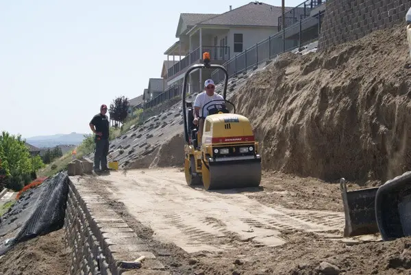
slanted column construction

When a column in a structure is perfectly straight, first-order bending moment and other internal stresses are induced due to the externally applied loads. However, when a column is inclined at an angle to the beams or floor that it is supporting, changes in bending moments are observed due to the eccentricity of the axial load with respect to the longitudinal axis column. Such effects can be investigated for pinned supports or fixed supports.

In the design of inclined columns (say in reinforced concrete or steel), it is usually very sufficient to analyse the structure and obtain the design internal forces (bending moment, shear, and axial force) using first-order linear analysis. However, when required, the analysis can be extended to second-order non-linear analysis to account for secondary effects which may affect the stability of the column.

To verify the effect of inclination on the design of columns, let us investigate the following cases of a column with a fixed base in reinforced-concrete construction.

Dimensions of beam = 600 x 300 mm
Dimensiond of column = 300 x 300 mm
Ultimate load (factored load) on the beam = 70 kN/m

C1
C2
C3

When the frames were analysed using first-order linear analysis, the following results were obtained;

CASE A

case 1

Maximum column design axial force = 220.219 kN
Column design shear force = 22.880 kN
Column design moment = 61.313 kNm

CASE B

CASE B

Maximum column design axial force = 241.712 kN
Column design shear force = 19.608 kN
Column design moment = 56.624 kNm

CASE C

CASE C

Maximum column design axial force = 226.991 kN
Column design shear force = 20.892 kN
Column design moment = 59.247 kNm

From the analysis results, it could be seen that case A gave the highest column moment but the least axial force, while case B gave the lowest column design moment but highest column axial force. The design of the column can then be carried out for each of the cases presented.

Strengthening of Flat Slabs with Cut-Out Openings

A flat slab is a type of reinforced concrete floor system where the slab is supported directly by columns, instead of beams. This system offers many advantages such as reduced headroom, flexibility in the distribution of services, reduced formwork complexity during construction, etc. Strengthening of flat slabs may become necessary especially when openings are introduced.

According to recent research (2021) from the Department of Civil Engineering, University of Wasit, Iraq, openings can be created in a slab after construction in order to pass the new services that satisfy the occupants’ desires, such as water or gas piping, ventilation, electricity, elevator, and staircase. The creation of openings in a flat slab has been found to significantly reduce the structural integrity of the floor.

Flat slabs can undergo brittle failure due to punching shear around the columns when the thickness of the slab is insufficient and/or when punching shear reinforcement is not provided. According to Hussein et al (2021), the possibility of punching shear failure increases by creating openings next to the columns due to removing a substantial amount of concrete from the critical section around columns, which is responsible for resisting the punching force. This is usually accompanied by the cutting of several flexural reinforcement bars.

flat slab open

This undesirable impact of openings gets more severe when they are not taken into account during the design, or they are installed after the construction of slabs. The opening influence could be minimized when they are positioned away from the columns, or the slab depth is increased.

From many research works carried out on flat slabs with openings, the following conclusions were reached. The full references and details of the research works can be found in Huessein et al., (2021).

  1. For openings of the same size, the strength reduction was more significant as the number of openings around the column increased.
  2. The influence of openings on the strength of slabs is greater when they are constructed in large sizes, especially when the size of the opening is greater than the size of the corresponding column.
  3. The impact of the opening could be reduced by shifting them far away from the supporting columns. Two far openings were found to be less detrimental than ones adjacent to column’s faces.
  4. Openings located at column corners reduced the strength of slabs more than openings placed in front of the column
  5. For openings of the same number and size, the arrangement of openings as the letter (L) around the column caused a lesser drop in the slabs’ punching strength.

In general, the reported maximum reduction in the slabs’ strength due to openings was about 29% relative to the solid equivalents.

It, therefore, makes sense to strengthen flat slabs with cut-out opening, especially when the effect of the opening was not taken into account during the design. Therefore, Hussein et al (2021) decided to investigate the effects of strengthening flat slabs with cut-out openings using different materials. The strengthening techniques investigated in the study were Carbon Fiber Reinforced Polymer (CFRP), steel plates, steel bars, and near-surface mounted Engineered Cementations Composite (ECC) with steel mesh. The findings were published in Case Studies of Construction Materials (Elsevier).

brrt
Fig 1: Details of the specimens used in the investigation (Hussein et al, 2021)

In order to investigate how strengthening can retrieve the lost mechanical strength of slab with openings, six reinforced concrete slabs were prepared with dimensions of 1300 x 1300 x 120 mm. One of them was reference without opening, whereas the others contained a square edge opening of 350 mm side. For slabs with openings, one specimen was the control left without strengthening, and the remaining four were strengthened utilizing various methods stated above.

Strengthening of Flat Slabs
drrt
Fig 2: Details of the investigation techniques used in the research (Hussein et al, 2021)

The details of the preparation of the specimens can be found in Hussein et al, (2021). After the curing process completed, the specimens were tested under the influence of uniform loading. The samples were moved into a testing steel rig and rested at their corners on supporting steel plates, measuring 200 x 200 x 30 mm to simulate the real supporting columns. Nevertheless, the rotations around these plates were not restricted. The uniform loading was applied incrementally with the help of a hydraulic jack up to failure.
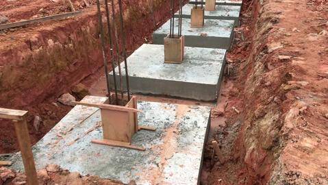
The major results of the experiment are shown below (Hussein et al., 2021);

experimental result of the tested slab

Based on the experiments by Hussein et al (2021) conducted on six reinforced concrete slabs, including edge openings and strengthened using four various methods, tested under uniformly distributed loads, the following points can be put forward as the essential outcomes;

1. Installation of an opening at the edge of a flat slab resting on four columns and subjected to uniformly distributed load did not change the failure modes. However, the losses in strength, ductility, and toughness were 20.6 %, 16.2 %, and 38 %, respectively when compared with the solid slab.
2. Among the four adopted methods of strengthening, the use of embedded steel bars and EEC altered the failure mode from brittle due to punching shear to more ductile combined flexural-shear modes.
3. The effectiveness of retrofitting techniques in restoring the lost mechanical properties of flat slabs due to openings was found to relate directly to the bond strength between the strengthening materials and the slab surface. Accordingly, the embedded steel bars technique was the most efficient, whereas the ECC was the least efficient method.
4. The strengthening materials should be extended as long as possible from the opening edge in order to achieve a sufficient development length. Hence, the retrofitting materials’ ultimate strength can arrive, and the debonding can be delayed.
5. None of the strengthening methods managed to restore the total missing strength of slabs due to openings. The use of embedded steel bars achieved the most significant upgrading in the slab strength, about 22.2 % over that of the slab with opening and 3 % below the solid slab’s strength.

References
Hussein M. J., Jabir H. A., Al-Gasham T. S. (2021): Retrofitting of reinforced concrete flat slabs with cut-out edge opening. Case Studies in Construction Materials 14 (2021) e00537 https://doi.org/10.1016/j.cscm.2021.e00537

Disclaimer
The contents of the above-cited research work have been presented on www.structville.com because it is an open-access article under the CC BY-NC-ND license (http://creativecommons.org/licenses/by-nc-nd/4.0/)


How to Distribute HB Live Load to Bridge Girders

In the UK, HB loads are used to represent abnormal traffic on a bridge deck. Even though the use of HA and HB loads as traffic actions has been replaced with Load Models 1 to 4 of EN 1991-2, the use of HB load is still applied in the design of bridges especially in Nigeria. It is very important, therefore, to know how to analyse bridge girders (in beam and slab bridges) for HB loads in order to obtain the design forces due to moving traffic.

There are many methods through which the effects of traffic wheel load can be obtained on the longitudinal components of a bridge deck. Some of these methods are;

The simplified methods of analysing bridge decks are known as the manual methods. While bridge design all over the world is majorly carried out using computers, the simplified methods (which are pretty quick to apply) can be used for quick checks or for preliminary and/or detailed design. The difference between the results from computer methods and simplified methods is often not very wide.

The basis of many simplified/manual methods is the distribution coefficient methods, e.g. Morice and Little (1956). These methods can be applied manually to obtain the values of various load effects at any reference point on a transverse section of the bridge.

For most of the load distribution coefficient methods, a right simply supported bridge is idealized as an orthotropic plate whose load distribution characteristics are governed by two dimensionless parameters α and θ. These parameters depend largely on the geometry of the bridge deck (which is usually known prior to the analysis).

In North America, the simplified method of bridge deck analysis is widely used. Unlike the distribution coefficient methods, the simplified methods of bridge analysis provide only the maximum action effect for the purposes of design. As a result, a lesser computational effort is required when using this method compared with the distribution coefficient method. These simplified methods are permitted by the current and past design codes, being the AASHTO Specifications (1998, 2010), the CSA Code (1988), the Ontario Highway Bridge Design Code (1992), and the Canadian Highway Bridge Design Code (2000, 2006).

The results from the North American simplified methods are reliable and can be obtained rather quickly. It is important to note that the analysis depends on the specification of the magnitude and placement of the design live loads, and accordingly are not always transportable between the various design codes.

The D-Method of Bridge Deck Analysis

In the simplified method of analysis, a longitudinal girder, or a strip of unit width in the case of slabs, is isolated from the rest of the structure and treated as a one-dimensional beam. This isolated beam is subjected to loads comprising one line of wheels of the design vehicle multiplied by a load fraction (S/D), where S is the girder spacing and D, having the units of length, has an assigned value for a given bridge type (Bakht and Mufti, 2015).

concept of the D method bridge deck
Fig 1: Transverse distribution of longitudinal moment intensity (Bakht and Mufti, 2015)

The concept of the factor D can be explained with reference to the figure above, which shows schematically the transverse distribution of live load longitudinal moment intensity in a slab-on-girder bridge at a cross-section due to one vehicle with two lines of wheels.

The intensity of longitudinal moment, having the units of kN.m/m, is obtained by idealizing the bridge as an orthotropic plate. A little consideration will show that the maximum girder moment, Mg, for the case under consideration occurs in the second girder from the left.

The moment in this girder is equal to the area of the shaded portion under the moment intensity curve. If the intensity of maximum moment is Mx(max) then this shaded area is approximately equal to SMx(max), so that:

Mg ≃ SMx(max) —— (1)

It is assumed that the unknown quantity Mx(max) is given by:

Mx(max) = M/D —— (2)

where M is equal to the total moment due to half a vehicle, i.e., due to one line of wheels. Substituting the value of Mx(max) from Eq. (2) into Eq. (1):

Mg = M(S/D) —— (3)

Thus if the value of D is known, the whole process of obtaining longitudinal moments in a girder is reduced to the analysis of a 1-dimensional beam in which the loads of one line of wheels are multiplied by the load fraction (S/D).

Simplified Method of Analysis for HB Load

A simplified method for two-lane slab-on-girder bridges in Hong Kong was presented by Chan et al. (1995). This was based on HB loads that are popularly used for bridge design in the UK.

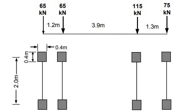
The HB loading comprises four axles, with four wheels in each axle. The weights of the wheels are governed by the units of the HB loading. In Great Britain,we have 30 units, 37.5, and 45 units of HB. Each unit of HB is equal to 10 kN. For instance, for 45 units of HB load, each axle has a total load of 450 kN, while each wheel has a load of 112.5 kN. It should, however, be noted that the units of the design loading does not affect the simplified method presented by Chan et al. (1995).

HB wheel load configuration
Fig 2: HB wheel load arrangement

According to Chan et al (1995), the longitudinal flexural rigidity per unit width Dx, of slab-on-girder bridges in Hong Kong lies between two bounds defined by the following equations.

Dx = 48000L + 5100L2 (upper bound) —— (4)
Dx = 2000L + 3650L2 (lower bound) —— (5)

where the span of the bridge L is in metres and Dx in kN.m.

From a study of a large number of slab-on-girder highway bridges in Hong Kong, it was determined that the ranges of the various parameters which influence the transverse load distribution characteristics of a bridge are as follows.

(a) The deck slab thickness, t, varies between 150 and 230 mm, with the usual value being 200 mm.
(b) The centre-to-centre spacing of girders, S, varies between 0.2 and 2.0 m, with the usual value being 1.0 m.
(c) The lane width, We, varies between 3.2 and 3.8 m, with the usual value being 3.5 m.
(d) The vehicle edge distance, VED, being the transverse distance between the centre of the outermost line of wheels of the HB loading and the nearest longitudinal free edge of the bridge, varies between 0.75 and 5.00 m, with the usual value being 1.00 m.

From the above observations, the following values of the various parameters were adopted for the developmental analyses conducted for developing the simplified method: t = 200 mm; S = 1.0 m; We = 3.5 m; and VED = 1.00 m. In addition, it was assumed that the deck slab overhang beyond the outer girders was 0.55 m. Bridges with spans of 10, 20, 30 and 40 m were selected for the developmental analyses.

Chan et al. (1995), having plotted the values of D from the above analyses against the span length L, found that these values of D are related to L according to the following equations with a reasonable degree of accuracy, provided that the design value of D, i.e. Dd, is corrected.

For internal girders having L < 25 m:
D = 1.2 – 3.5/L —— (6)

For internal girders having L ≥ 25 m:
D = 1.06 —— (7)

For external girders having L < 30 m:
D = 0.95 + 2.1/L —— (8)

For external girders having L ≥ 30 m:
D = 1.03 —— (9)

The correcting equation for obtaining Dd is as follows;

Dd = D(1 + µCw/100) —— (10)

Where;
µ = (3.5 – We)/0.25 —— (11)

The values of cw for internal and external girders can be read from the chart below;

values of cw
Fig 3: Values of cw (Chan et al, 1995)

The following conditions must be met for applying the simplified method.

  1. The value of Dx lies between the upper and lower bound values given by Eqs. (4) and (5), respectively.
  2. The bridge has two design lanes
  3. The width is constant or nearly constant, and there are at least three girders in the bridge.
  4. The skew parameter ε = (S tan ψ)/L does not exceed 1/18 where S is girder spacing, L is span and ψ is the angle of skew.
  5. For bridges curved in plan, L2/bR does not exceed 1.0, where R is the radius of curvature; L is span length; 2b is the width of the bridge.
  6. The total flexural rigidity of transverse cross-section remains substantially the same over at least the central 50% length of each span.
  7. Girders are of equal flexural rigidity and equally spaced, or with variations from the mean of not more than 10% in each case.
  8. The deck slab overhang does not exceed 0.6S, and is not more than 1.8 m.

The steps for applying the simplified method in the analysis of bending moment due to HB load on a bridge girder are;

  1. Calculate the value of D from the relevant of Eqs. (6, 7, 8, and 9); for simply supported spans, L is the actual span length, and for continuous span bridges, the effective L for different spans should be obtained.
  2. For the design lane width, We, obtain μ from Eq. (11) and Cw from the chart and thereafter obtain Dd from Eq. (10).
  3. Isolate one girder and the associated portion of the deck slab, and analyse it by treating it as a one-dimensional beam under one line of wheels of the HB loading. The moment thus obtained at any transverse section of the beam is designated as M.
  4. For any of the internal and internal girders, obtain the maximum moment at the transverse section under consideration by multiplying M with (S/Dd), where Dd is as obtained in Step (b) for the relevant internal or external girders.

Worked Example

Obtain the maximum sagging moment in an interior girder of a one-span bridge deck carrying 45 units of HB load. The configuration of the bridge deck is shown below;

bridge deck section 1
Fig 4: Bridge deck section

Actual span lengths, L = 18.0 m
Bridge width, 2b = 8.7 m
Carriageway width = 7.2 m
Number of notional lanes = 2
Design lane width (notional lane width) = We = 3.6 m
Deck slab thickness = 0.20 m
Girder spacing S = 1.80 m
Deck slab overhang = 0.75 m
Vehicle edge distance VED = 1.35 m

HB line beam analysis

Isolating a girder of the bridge and placing a line of HB wheel load on it to determine the maximum moment. The wheel load position that will produce the maximum moment is shown below;

HB load line beam analysis
Fig 5: Line beam analysis of an isolated girder under one line of HB load

When analysed;

M = 1203.75 kNm

From equations (6) and (8);

Internal girder (L < 25 m)
D = 1.2 – 3.5/L = 1.2 – 3.5/18 = 1.0055

External girder (L < 25 m)
D = 0.95 + 2.1/L = 0.95 + 2.1/18 = 1.067

Applying a correction factor to the value of D;
Dd = D(1 + µCw/100)

Where;
µ = (3.5 – We)/0.25 = (3.5 – 3.6)/0.25 = -0.4

For internal girder;
Cw = 6L/40 = (6 x 18)/40 = 2.7%
Dd = 1.0055[1 – (0.4 x 2.7)/100] = 0.9946
Load Fraction S/D = 1.8/0.9946 = 1.8097

For external girder;
Cw = 14 %
Dd = 1.067[1 – (0.4 x 15)/100] = 1.00298
Load Fraction S/D = 1.8/1.00298 = 1.794

Therefore the maximum moment in the internal girder = 1.8097 x 1203.75 = 2178 kNm
Therefore the maximum moment in the external girder = 1.794 x 1203.75 = 2159 kNm

Kindly check for the accuracy of this answer using any method available to you and post your findings in the comment section.

Disclaimer:
Most of the procedures presented here are as described by Bakht and Mufti (2015) with minor alterations after studying the original article cited (Chan et al, 2015). The copyright to those contents, therefore, belongs to the original owners. The worked example used to illustrate the procedure was however developed by Structville.com

References
Bakht B., Mufti A. (2015): Bridge Analysis, Design, Structural Health Monitoring, and Rehabilitation. Springer
Chan THT, Bakht B, Wong MY (1995): An introduction to simplified methods of bridge analysis for Hong Kong. HKIE Trans 2(1):1–8
Morice P. B. and Little G. (1956): The Analysis of Right BridgeDecks Subjected to Abnormal Loading. Cement and Concrete Association, London, Report Db 11

Transcona Grain Elevator Failure: Lessons on Bearing Capacity

The Canadian Pacific Railway Company in the year 1913 constructed the Transcona grain elevators of about 36400 m3 capacity to provide relief for the Winnipeg Yards during the months of peak grain shipment. The structure consisted of a reinforced concrete work-house, and an adjoining bin-house, which contained five rows of 13 bins, each 28 m in height and 4.4 m in diameter.

The bins were based on a concrete structure containing belt conveyors supported by a reinforced concrete shallow raft foundation (Puzrin et al, 2010). The reinforced concrete raft foundation was 600 mm thick, with dimensions of 23.5 x 59.5 m.

Excavation for the construction of the elevator foundations started in 1911, and the first 1.5m depth of soil at the site was rather soft. Beyond the soft clay layer was a relatively stiff blue clay, typical for that area, and locally known as the “blue gumbo”.

According to literature cited by Puzrin et al (2010), no borings or extensive geotechnical investigations were carried out prior to the construction. This is not a surprise, given the level of technology and knowledge about soil engineering at that time. However, an in-situ bearing capacity test (test loading applied using a specially constructed wooden framework) was performed at a depth of 3.7 m.

According to the literature cited by Puzrin et al (2010), the plate load test result indicated that the soil was capable of bearing a uniformly distributed load of at least 400 kPa. The maximum foundation pressure from the bins at maximum load was not expected to exceed 300 kPa, therefore the tests appeared satisfactory to the engineers. Furthermore, they assumed that the “blue gumbo” at the site had similar characteristics and a depth to that on which similar raft foundations of many heavy structures had been founded in the vicinity of Winnipeg. This eventually turned out not to be so.

After the structure was completed, the filling was begun and grain was distributed uniformly between the bins. On October 18, 1913, after the elevator was loaded to 87.5% of its capacity, settlement of the bin-house was noted. Within an hour, the settlement had increased uniformly to about 300 mm following by a tilt towards the west, which continued for almost 24 hours until it reached an inclination of almost 27 degrees (Puzrin et al, 2010).

 Transcona grain elevator
Fig 1: Transcona grain elevator (a) Before failure (b) After failure

Several wash-borings were made immediately after the failure, showing that the elevator was underlain by rather uniform deposits of clay. This finding was in agreement with the geological history of the area, according to which extensive fine-grained sediments were deposited in the waters of the glacial Lake Agassiz which came into being when the Wisconsin ice-sheet blocked the region’s northern outlet.

It was noted that no laboratory test was carried out on the samples collected during the wash borings, but classification was done based on visual observation. The wash-borings, therefore, confirmed the designers’ assumptions of uniform clay layer, and the failure of the Transcona Grain Elevator remained a mystery for another 40 years.

It was thought that, if the smaller-scale plate loading tests predicted a safety factor of more than 1.3 (400/300 = 1.33), and the soil profile is homogeneous, how could the foundation fail? The answer to this question was given by Peck and Bryant (1953) who, in 1951 (38 years later), made two additional borings, far enough from the zone of failure to be in material unaffected by the displacements (Puzrin et al, 2010).

They obtained undisturbed soil samples and performed unconfined compression strength tests (triaxial shear tests with zero confining stress), which produced some eye-opening results shown in Fig 2.

unconfined compression
Fig 2: Soil profile below the elevator (after Peck and Bryant, 1953) (a) classification; (b) unconfined compression strength

On observation of the unconfined compressive strength (qu) result of the site, there are two easily distinguishable layers (Fig. bb). The upper one, a 7.5 m thick stiff clay layer with qu = 108 kPa (undrained shear strength cu = qu/2 = 54 kPa), appears to be resting on a softer clay layer with qu = 62 kPa (cu = 31 kPa). This finding suggests that the elevator failure was most likely caused by the insufficient bearing capacity of its foundation.

In a bearing capacity failure, a failure mechanism is formed below the foundation (Fig. 3b). The settlement takes place much faster and without decrease of the soil volume. Therefore, the displaced soil has to find itself an exit, causing a ground heave in the vicinity of the structure. This ground heave is a distinctive feature of the failure of the Transcona Grain Elevator (Puzrin et al, 2010).

bearing capacity failure
Fig 3: Bearing capacity failure: (a) settlement; (b) failure; (c) the ground heave (Puzrin et al, 2010)

According to (Puzrin et al, 2010), the particular problem of the Transcona Grain Elevator was that the failure mechanisms of the plate loading tests were apparently confined to the upper stiffer clay layer, due to the relatively small size of the plates. The elevator foundation, however, developed a much deeper failure mechanism which entered the weaker clay layer, significantly reducing the bearing capacity.

This led the researchers to consider the two-layer model and other bearing capacity theories that are adequate to describe the situation on the site. Details of this can be found in Puzrin et al, (2010).

It was observed that the true failure contact pressure was 293 kPa. In the original design, it was assumed that the soil profile was homogeneous with the properties of the stiff upper layer uc1 = 54 kPa. In this case, the bearing capacity of the foundation was calculated as 386 kPa (applying the appropriate bearing capacity, shape, and depth correction factors). This was found to be close to the 400 kPa obtained from the plate load tests.

Note that if the soil was homogeneous but with the properties of the weaker lower layer (uc2 = 31 kPa), the resulting bearing capacity would be 251 kPa. If this value was available to designers, the result would actually not be that bad: not only the elevator would not fail, it would not even be too much overdesigned.

A more sophisticated analysis, based on a two-layer model, should produce more accurate predictions. First, the reseachers followed Peck and Bryant (1953) and used the approximate method based on the Prandtl solution using a weighted average of the undrained shear strength. This gave a bearing capacity of 321 kPa which is 10% larger than the failure pressure. While the Prandtl solution for a homogeneous soil is the exact solution, in the two-layer approximation, it was observed that it is not only inaccurate, but it is also not conservative and could lead to failure.

The scoop mechanism, in contrast, provides a remarkably good bearing capacity estimate of 297 kPa. Being an upper bound, this value, as expected, is higher than the true failure pressure of 293 kPa, but only marginally. It would provide an excellent estimate for the design of the elevator if only the Soil Mechanics was more mature in those days and the soil properties were properly determined.

Source:
The information in this article was majorly obtained from:
Puzrin A. M., Alonso E.E., Pinyol N. M. (2010): Geomechanics of Failures. Springer. DOI 10.1007/978-90-481-3531-8

Bridge Design Textbook

We are pleased to announce the release of our publication on the ‘Design of Reinforced Concrete Bridges‘. This publication is part of the proceedings of our January 2021 Webinar on Bridge Design.

The publication essentially contains full calculation sheets on the analysis and design of different structural components of a T-beam bridge (beam and deck slab bridge) such as;

  1. Deck slab
  2. Reinforced Concrete Girders (beams)
  3. Bearings
  4. Pier Cap
  5. Piers
  6. Abutment
  7. Pile Cap
bridge deck section
bridge design

Both computer and manual methods were adopted in the analysis presented, and the design considers the effect of wind, temperature, and secondary traffic loads such as braking, traction, etc on the bridge. Other elements such as parapets, precast planks (filigree slab) for receiving the in-situ topping of the deck slab, etc were also considered in the design. The design was carried out according to the British Standards.

To obtain the book for NGN 5,000 only, click HERE

BRIDGE SHOWING INFRASTRUCTRES DESIGNED BY RMC

Some excerpts from the publication are shown below;

bridge deck section
The typical bridge deck section
longitudinal section
Typical longitudinal view of the bridge
bending moment on bridge deck slab due to dead load
vertical shear in deck slab
main beam design
Temperature effect
bending moment in beams
bridge reinforcement calculation
piers loading
abutment design

To obtain the book for NGN 5,000 only, click HERE

bridge design

Deflection of Trusses | Worked Example

Trusses deflect when loaded. Under gravity loads, this is usually characterised by the sagging of the top and bottom chords, and the consequent movement of the web and diagonal members. In the design of trussed structures such as roofs and bridges, it is always important to keep the deflection of the trusses to a minimum in order to maintain the appearance and functionality of the structure. Deflection of trusses can be assessed manually using the virtual work method (unit load method), direct stiffness method, or finite element analysis.

The deflection of roof trusses is often limited to span/240. On the other hand, a span to depth ratio of 15 is often found adequate for all practical purposes. For bridges, AASHTO design code states that the maximum deflection of a truss bridge due to live load should not exceed span/800. The principle of virtual work can be used to compute the maximum deflection of the truss, which is then compared to the allowable deflection.

In this article, we are going to explore how to determine the deflection of trusses using the virtual work method (unit load method). In the virtual work method, the truss is analysed for the axial forces due to the externally applied load. Subsequently, the external forces are removed and replaced with a unit virtual load at the node where the deflection is to be obtained. The direction of the unit load should be in the same direction with where the deflection is sought. The truss is re-analysed for the axial forces in the members due to the virtual unit load.

The summation of the deflection of the individual members using the formula below gives the deflection of the roof truss at the point of interest.

δ = ∑niNiLi/EiAi

Where;
n = axial force in member i due to virtual unit load
N = axial load in member i due to externally applied load
L = length of member
E = Modulus of elasticity of member
A = Area of member

Worked Example

A truss is loaded as shown below. Obtain the vertical deflection at point C due to the externally applied load (AE = constant).

deflection of trusses

Support Reaction due to externally applied load
Let MG = 0;
9Ay – (6 × 6) – (4 × 3) + (10 × 3) = 0
Ay = 2 kN↑

Let MA = 0;
9Gy – (10 × 3) – (4 × 6) – (6 × 3) = 0
Gy = 8 kN ↑

Let Fx = 0
Ax = 10 kN ←

Internal forces due to the externally applied loads

Joint A

JOINT A

Fy = 0
2 + FABsin45 = 0
FAB = -2.8 kN (compression)

Fx = 0
-10 + FAC + FABcos45 = 0
-10 + FAC – 2.8cos45 = 0
FAC = 12 kN (tension)

Joint B

JOINT B


Fx = 0
FBD – FBAcos45 = 0
FBD – 2.8cos45 = 0
FBD = -2 kN (compression)

Fy = 0
-6 – FBC – FBAsin45 = 0
-6 – FBC + 2.8sin45 = 0
FBC = -4 kN (tension)

JOINT C

JOINT C

Fy = 0
FBC + FCDsin45 = 0
-4 + FCDcos45 = 0
FCD = 5.656 kN (tension)

Fx = 0
-FCA + FCDcos45 + FCE = 0
-12 + 5.656cos45 + FCE = 0
FCE = 8 kN (tension)

JOINT G

JOINT G

Fy = 0
8 + FGF = 0
FGF = -8 kN (compression)

Fx = 0
FGE = 0

JOINT F

JOINT F


Fy = 0
-FFG – FFEsin45 = 0
-(-8) – FFEsin45 = 0
FFE = 11.31 kN (tension)

Fx = 0
-FFD – FFEcos45 + 10 = 0
-FFD – 11.31cos45 + 10 = 0
FFD = 2 kN (tension)

JOINT E

JOINT E

Fy = 0
FED + FEFsin45 = 0
FED + 11.31sin45 = 0
FED = -8 kN (compression)

Having obtained the internal forces in all the members due to the externally applied loads, let us remove all the loads and replace them with a unit vertical load at point C as shown below;

TRISS WITH VIRTUAL LOAD

Support Reaction due to virtual load
Let MG = 0;
9Ay – (1 × 6) = 0
Ay = 6/9 = 0.667 ↑

Let MA = 0;
9Gy – (1 × 3) = 0
Gy = 3/9 = 0.333 ↑

Let Fx = 0
Ax = 0

When analysed using the same procedure as above;

FAC = 0.665 (tension)
FAB = -0.941 (compression)
FBC = 0.665 (tension)
FCE = 0.334 (tension)
FCD = 0.47 (tension)
FBD = 0.665 (compression)
FDE = 0.331 (compression)
FDF = 0.333 (compression)
FEF = 0.47 (tension)
FEG = 0
FGF = 0.333 (compression)

We can now form a table as follows;

MembernN (kN)L (m)nNL/AE
AC+0.665+12.003.00023.940
AB-0.940-2.804.24311.167
BC+0.665-4.003.000-7.980
CE+0.334+8.003.0008.016
CD+0.470+5.654.24311.267
BD-0.665-2.003.0003.990
DE-0.331-8.003.0007.944
DF-0.331+2.003.000-1.986
EF+0.470+11.314.24322.554
EG003.0000.000
GF-0.333-8.003.0007.992
∑niNiL = 86.904/AE

Therefore the vertical deflection at point C is 86.904/AE metres.

Design of Strap Footing | Cantilever Footing

Strap footings or cantilever footings are a special form of combined footings. They consist of two separate bases that are connected (balanced) by a strap beam. In the design of strap footing, it is assumed that the strap beam is rigid and does not transfer any load by bearing on the soil at its bottom contact surface.

Strap footing is necessary when the foundation of a column cannot be built directly under the column or when the column should not exert any pressure below. It is then necessary to balance it by a cantilever arm rotating about a fulcrum and balanced by an adjacent column (or a mass of concrete or by piles) in case of where footings cannot be built.

balanced bases

As was described above, balanced footings consist of two separate footings connected by a strap beam. In the design of balanced bases, uniform soil pressure can be assumed if we can make the centre of the areas of the system coincide with the centre of gravity of the loads. When these two centres do not coincide, we have the vertical load and moment acting on the system due to the eccentricity. As a result, the distribution of base pressure will not be uniform but can be assumed to be linearly varying.

The difference between balanced footings and cantilever footings can be described as follows. In a balanced footing, we make the centre of gravity of the loads and the centre of the areas coincide. Hence, the ground pressure will be uniform. In cantilever footings, in general, the two centres may not coincide, so we have a moment in addition to the vertical loads. Hence, the ground pressure will be varying.

Worked Example

Two columns with the following loading conditions are spaced 4 m apart. Due to site boundary constraints, design a strap footing for the columns, if the safe bearing capacity of the soil is 150 kN/m2; fck = 25 N/mm2; fyk = 500 N/mm2

ColumnSize (mm)Service Load (kN)Ultimate Load (kN)
C1300 x 300450617
C2300 x 300600822

Solution
We can either dimension each of the footings so that the CG of the areas and loads coincide, resulting in uniform pressure, or adopt
suitable base dimensions and then check the resulting ground pressure taking the unit as a whole, which may not be uniform, and design for non-uniform pressure. We will adopt the first method.

Design of strap footing

Step 1: Preliminary sizing of the footing of the exterior column
Base area (A1) needed for column C1 = Service load/Safe bearing capacity = 450/150 = 3m2
Try a rectangular footing of size 1.75m wide x 2 m long along the centre line (Area provided = 3.5 m2)

Hence, we fix the fulcrum at 2.0/2 = 1.0 m from the end near C1.

Therefore;
Distance of R1 from C1 = L1 = 1.0 – 0.3 = 0.7 m from C1
Distance of C2 from R1 = L2 = 4 – 0.7 = 3.3 m

Taking moment about C2;
3.3R1 = 450 x 4
R1 = 545.45 kN

Let the summation of the vertical forces be equal to zero;
R2 = 450 + 600 — 545.45 = 504.55 kN

Step 2: Check the factor of safety (FOS) against overturning using characteristic loads
FOS = C2L2/C1L1 = (600 x 3.3)/(450 x 0.7) = 6.285 > 1.5 (Okay).

Step 3: Find the dimension of footing for R2 so that the CG of loads and areas coincides.
This is given by;
B = √(R2/SBC) = √(504.55/150) = 1.83 m
Adopt a footing 1.85 m x 1.85 m

Step 4: Recalculate the necessary breadth of footing F1 so that CG of loads and areas of footings coincides.
x1 = CG of loads = (C1 x 4)/(C1 + C2) = (450 x 4)/(450 + 600) = 1.714 m from C2

Let us find the CG of areas we have assumed.
Area of F2 = A2 = 1.85 x 1.85 = 3.4225 m2. Find Ax required for CG to be same as that of loads.

x2 = (A1 x 3.3)/(A1 + A2) = 1.714 (for a balanced base)
(A1 x 3.3)/(A1 + 3.4225) = 1.714
On solving; A1 = 3.698 m2

For a length of 2m, a width of 3.689/2 = 1.85 m is required.
Therefore slightly increase the width of A1 to 1.85 m.

Hence;
A1 = (1.85 x 2)m = 3.7 m2
A2 = (1.85 x 1.85)m = 3.4225 m2

Step 5: Calculate uniform pressure for factored load
qnet = (617 + 822)/(3.7 + 3.4225) = 202.03 kN/m2

You can verify independently;
At ultimate limit state; R1 = (545.45 x 617)/450 = 747.87 kN
Soil pressure under base 1 = 747.87/3.7 = 202.13 kN/m2

At umtimate limit state R2 = (504.55 x 822)/600 = 691.23 kN
Soil pressure under base 2 = 691.23/3.4225 = 201.967 kN/m2

Step 6: Design of footing F1
Let the width of the strap beam be 0.3 m. The maximum moment will occur at the face of the strap beam (overhang of the strap beam).

Length of overhang = (1.85 – 0.3)/2 = 0.775 m on both sides of the beam

MEd = ql2/2 = (202.13 x 0.7752)/2 = 60.7 kNm

Assuming a footing depth h = 400 mm and concrete cover of 50 mm;
Effective depth d = 400 – 50 – 8 = 342 mm.

Critical design moment at the face of the strap beam
MEd = 125 kNm/m
k = MEd/(bd2fck) = (60.7 x 10⁶)/(1000 x 3422 x 25) = 0.0207
Lever arm = z = d[0.5 + √(0.25 – 0.882k)] = 0.95d
⇒ z = 0.95d = 0.95 x 342 = 325 mm
⇒ As = MEd/0.87fykz = (60.7 x 10⁶)/(0.87 x 500 x 325) = 429 mm2/m
Asmin = 520 mm2/m

Provide H12 @ 200 c/c (Asprov = 565 mm2/m)

Beam shear
Check critical section d away from the face of the strap beam
VEd = 202.13 x (0.775 – 0.342) = 87.522 kN/m
vEd = 87.522/342 = 0.256 N/mm2

vRd, c = CRd, c × k × (100 × ρ1 × fck) 0.3333
CRd, c = 0.12
k = 1 + √ (200/d) = 1 + √ (200/342) = 1.76
ρ = 565/(342 × 1000) = 0.00165
vRd, c = 0.12 × 1.76 × (100 × 0.00165 × 25)0.333 = 0.338 N/mm2
=> vEd (0.256 N/mm2) < vRd,c (0.338 N/mm2) beam shear ok

Step 7: Design of the strap beam
Equivalent line load under column base 1 = 202.13 x 1.85 = 373.94 kN/m
Equivalent line load under column base 2 = 202.13 x 1.85 = 373.94 kN/m

loading of strap footing


The shear force values at the critical points are;
V1L = (0.15 x 373.94) = 56.09 kN
V1R = 56.09 – 617 = -560.9 kN
Vi = (373.94 x 2) – 617 = 130.88 kN
V2L = 130.88 + (373.94 x 0.925) = 476.774 kN
V2R = 476.774 – 822 = -345.226 kN
Vj = -345.225 + (373.94 x 0.925) = 0

shear force diagram of strap footing 2

The maximum bending moment will occur at the point of zero shear which is 1.5 m from column A. This can be easily obtained by using similar triangles.

Mmax = (373.94 x 1.652)/2 – (617 x 1.5) = -416.474 kNm (hogging moment).
The maximum sagging moment will occur under column C2;
Mmax = (373.94 x 0.9252)/2 = 159.976 kNm

Assume a total depth of 600 mm for the beam;
Effective depth = 600 – 50 – 10 – 10 = 530 mm
k = MEd/(bd2fck) = (416.474 x 10⁶)/(300 x 5302 x 25) = 0.1976

Since k < 0.167, compression is required. This means that the beam will have to be designed as a doubly reinforced beam.
Area of compression reinforcement AS = (MEd – MRd) / (0.87fyk (d – d2))

MRd = 0.167fckbd2 = (0.167 × 25 × 300 × 5302) × 10-6 = 351.827 kNm

d2 = 50 + 10 + 10 = 70 mm

AS2 = ((416.474 – 351.827) × 106) / (0.87 × 500 × (530 – 70)) = 323 mm2
Asmin = 234 mm2
Provide 4H16 Bottom (Asprov = 804 mm2)
Confirm that this reinforcement can satisfy for bending under column C2.

Area of tension reinforcement As1 = MRd / (0.87fyk z) + AS2
Where z = d[0.5+ √(0.25 – 0.882K’)]
K’ = 0.167
z = d[0.5+ √((0.25 – 0.882(0.167))] = 0.82d
As1 = MRd/(0.87fyk z) + AS2 = (351.827 × 10⁶) / (0.87 × 500 × 0.82 × 530) + 323 mm2 = 2184 mm2

Provide 8H20 Top (ASprov = 2512 mm2)

Shear Design
Using the maximum shear force for all the spans
Support A; VEd = 560.9 kN
VRd,c = [CRd,c.k. (100ρ1 fck)1/3 + k1cp]bw.d
CRd,c = 0.18/γc = 0.18/1.5 = 0.12
k = 1 + √(200/d) = 1 + √(200/530) = 1.61 > 2.0, therefore, k = 1.61

Vmin = 0.035k3/2fck1/2
Vmin = 0.035 × 1.613/2 × 251/2 = 0.357 N/mm2

ρ1 = As/bd = 1256/(300 × 530) = 0.007899 < 0.02;

VRd,c = [0.12 × 1.61(100 × 0.007899 × 25)1/3] × 300 × 540 = 84597.88 N = 84.597 kN
Since VRd,c (84.597 kN) < VEd (560.9 kN), shear reinforcement is required.

The compression capacity of the compression strut (VRd,max) assuming θ = 21.8° (cot θ = 2.5)
VRd,max = (bw.z.v1.fcd)/(cotθ + tanθ)
V1 = 0.6(1 – fck/250) = 0.6(1 – 25/250) = 0.54
fcd = (αcc fck)/γc = (0.85 × 25)/1.5 = 14.167 N/mm2
Let z = 0.9d
VRd,max = [(300 × 0.9 × 540 × 0.54 × 14.167)/(2.5 + 0.4)]× 10-3 = 384.619 kN

Since VRd,c < VRd,max < VEd
The beam is subjected to high shear load, we need to modify the strut angle.
θ = 0.5sin-1[(VRd,max /bwd)/0.153fck(1 – fck/250)]
(VRd,max /bwd) = 2.418 N/mm2
0.153fck(1 – fck/250) = 3.4425
θ = 0.5sin-1[(2.418/3.4425] = 22.31°

Since θ < 45°, section is OK for the applied shear stress

Hence Asw/S = VEd /(0.87fykzcotθ) = 560900/(0.87 × 500 × 0.9 × 530 × 2.437) = 1.109
Maximum spacing of shear links = 0.75d = 0.75 × 530 = 597.5
Provide 4 legs Y10 @ 250mm c/c as shear links (Asw/S = 1.256) Ok


Design of Gantry Crane Girders | BS 5950

Overhead cranes are usually required in industrial or storage buildings for the lifting and/or movement of heavy loads from one point to another. These overhead cranes can be manually operated (MOT) or electrically operated (EOT). A Gantry girder may therefore be defined as a structural beam section, with or without an additional plate or channel connected to the top flange to carry overhead electric travelling cranes.

The typical components of an overhead travelling crane are shown in the figure below;

crane
Fig 1: Typical components of overhead crane

Crane gantry girders are usually designed to resist unsymmetrical forces and moments from vertical loads and reactions, horizontal forces, longitudinal forces, fatigue, and impact forces. The design of a gantry crane girder, therefore, involves the selection of a suitable and workable steel model and section to satisfy the machine (crane) requirements, loading, equipment, etc without leading to any structural or service failure.

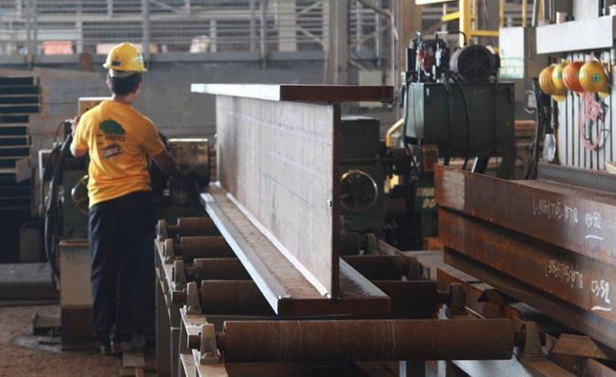
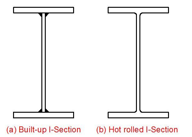
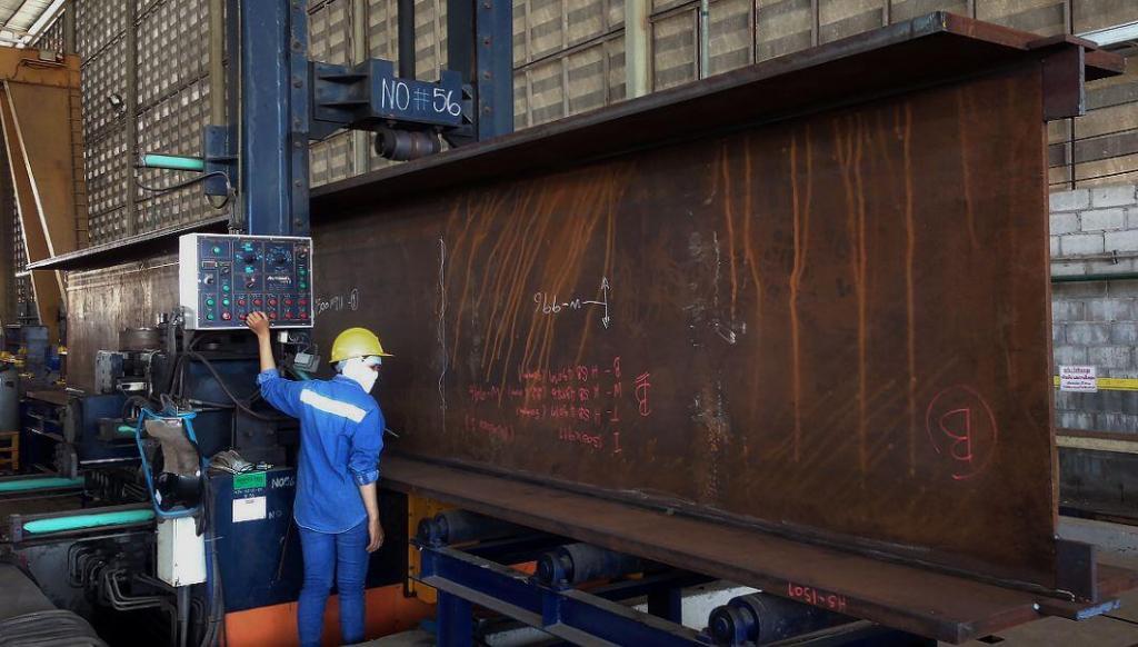
Normally, for medium-duty (say 25 to 30 t capacity) cranes, standard universal rolled I-beams are used. In the design of gantry girders with long spans supporting heavy vertical dynamic crane wheel loads with transverse horizontal crane surges, the standard universal rolled beam section is not adequate as a gantry girder; the built-up section of a plate girder is adopted instead.

built up plate girder section
Fig 2: Built-ip plate girder sections

Gantry girders are usually subjected to very high vertical impacts, transverse horizontal surges, and longitudinal horizontal surges depending on their lifting capacity and geometry.

The transverse horizontal force generated either of the two following factors or by a combination both of it;

  1. Thrust from sudden application of the brakes of the crab motor, causing abrupt stoppage of the crab and load when transversing the crab girders. This thrust is resisted by the frictional force developed between the crab wheels and crab girders, is then transferred to the crosshead girders of the crane, and finally transferred as point loads through the main wheels of the crane into the top flange of the crane girders.
  2. A crane often drags weights across the shop floor. If the weight is very heavy, this pulling action induces a transverse horizontal component of force ( a point load) on the crane girders through the crane wheels.

This transverse horizontal force will be transferred to the crane girders through the double-flanged crane wheels on the end carriages and the crane is designed to avoid the possibility of derailment. Due to the difficulties in determining this kind of force, the horizontal transverse force on each gantry girder is equal to 10% of the total load lifted.

Furthermore, during the traveling of the crane, the sudden application of brakes induces frictional resistance to the sliding of the locked wheels upon a rail fixed to the gantry girder. This frictional resistance, in turn, generates a horizontal force along the length of the gantry girder and finally transfers to the columns that support the gantry girder. This is usually the source of the longitudinal horizontal force.

Gantry girders may be simply supported or continuous over supports. Continuity over supports reduces the depth and cost, but any differential settlement of the supports may reverse the original design values of the moments in the sections, thus exceeding the allowable stress in the material, with consequent collapse of the member. So, we adopt simply supported gantry girders, particularly for very heavily loaded girders.

Design Example of a Gantry Crane Girder

Design a gantry to satisfy the manufacturer’s design data given below;

Crane capacity = 20 tonnes (200 kN)
Maximum load lifted = 200 kN.
Crane span = 13.0 m
Weight of crane bridge = 120 kN
Spacing of wheels = 1.2 m
End clearance of crane = 600 mm (minimum).
Minimum headroom from rail top = 4500 mm.
Weight of crab = (1/5 of maximum load lifted + 5 kN) = (1/5) × 200 + 5 = 45 kN.

Crane and Girder Details

Design of Gantry Crane Girders

Crane details
Self weight of crane bridge (excluding crab);  Wcrane = 120.0 kN
Self weight of crab; Wcrab = 25.0 kN
Crane safe working load (SWL); Wswl = 200.0 kN
Span of crane bridge; Lc = 13000 mm
Minimum hook approach; ah = 600 mm
No. of wheels per end carriage; Nw = 2
End carriage wheel centres; aw1 = 3000 mm
Class of crane; Q3
No. of rails resisting crane surge force; Nr = 1
Self weight of crane rail; wr = 0.5 kN/m
Height of crane rail;  hr = 100 mm

Gantry girder details
Span of gantry girder; L = 5000 mm
Gantry girder section type; Plain ‘I’ section
Gantry girder ‘I’ beam; UB 610x305x238
Grade of steel; S 275

Loading, Shear forces and Bending Moments

Unfactored self weight and crane rail UDL
Beam and crane rail self weight udl; wsw = (Massbm × gacc) + wr = 2.8 kN/m

Maximum unfactored static vertical wheel load
From hook load; Wh = Wswl × (Lc – ah)/(Lc × Nw) = 95.4 kN
From crane self weight (including crab);  Ws = [Wcrane/2 + Wcrab × (Lc – ah)/Lc]/Nw = 41.9 kN

Total unfactored static vertical wheel load; Wstat = Wh + Ws = 137.3 kN

Maximum unfactored dynamic vertical wheel load
From BS2573:Part 1:1983 – Table 4

Dynamic factor with crane stationary; Fsta = 1.30;
Dynamic wheel load with crane stationary; Wsta = (Fsta × Wh) + Ws = 165.9 kN
Dynamic factor with crane moving; Fmov = 1.25;
Dynamic wheel load with crane moving; Wmov = Fmov × Wstat = 171.6 kN
Max unfactored dynamic vertical wheel load;Wdyn = max(Wsta, Wmov) = 171.6 kN

Dynamic vertical wheel loads
Unfactored transverse surge wheel load
Number of rails resisting surge; Nr = 1
Proportion of crab and SWL acting as surge load;  Fsur = 10 %
Unfactored transverse surge load per wheel; Wsur = Fsur × (Wcrab + Wswl)/(Nw × Nr) = 11.3 kN

Surge wheel loads
Unfactored transverse crabbing wheel load
Unfactored transverse crabbing load per wheel; Wcra = max(Lc × Wdyn/(40 × aw1), Wdyn/20) = 18.6 kN

Unfactored longitudinal braking load
Proportion of static wheel load acting as braking load; Fbra = 5 %
Unfactored longitudinal braking load per rail; Wbra = Fbra × Wstat × Nw = 13.7 kN

Ultimate loads
Load Case 1 (1.4 Dead + 1.6 Vertical Crane)

Vertical wheel load; Wvult1 = 1.6 × Wdyn = 274.6 kN
Gantry girder self weight udl; wswult = 1.4 × wsw = 4.0 kN/m

Load Case 2 (1.4 Dead + 1.4 Vertical Crane + 1.4 Horizontal Crane)
Vertical wheel load; Wvult2 = 1.4 × Wdyn = 240.3 kN
Gantry girder self weight udl; wswult = 1.4 × wsw = 4.0 kN/m
Horizontal wheel load (surge); Wsurult = 1.4 × Wsur = 15.7 kN
Horizontal wheel load (crabbing); Wcrault = 1.4 × Wcra = 26.0 kN

Maximum ultimate vertical shear force
From load case 1; Vv = Wvult1 × (2 – aw1/L) + wswult × L/2 = 394.4 kN

Ultimate horizontal shear forces (load case 2 only)
Shear due to surge; Vsur = Wsurult × (2 – aw1/L) = 22.0 kN
Shear due to crabbing; Vcra = Wcrault = 26.0 kN

Maximum horizontal shear force; Vh = max(Vsur, Vcra) = 26.0 kN

Ultimate vertical bending moments and co-existing shear forces
Bending moment loadcase 1; Mv1 = Wvult1 × L/4 + wswult × L2/8 = 355.7 kNm
Co-existing shear force; Vv1 = Wvult1/2 = 137.3 kN

Bending moment loadcase 2; Mv2 = Wvult2 × L/4 + wswult × L2/8 = 312.8 kNm
Co-existing shear force;  Vv2 = Wvult2/2 = 120.1 kN

Ultimate horizontal bending moments (loadcase 2 only)

Surge moment; Msur = Wsurult × L/4 = 19.7 kNm
Crabbing moment; Mcra = Wcrault × L/4 = 32.5 kNm

Maximum horizontal moment; Mh = max(Msur, Mcra) = 32.5 kNm

Section Properties

Beam section properties
Area; Abm = 303.3 cm2
Second moment of area about major axis; Ixxbm = 209471 cm4
Second moment of area about minor axis; Iyybm = 15837 cm4
Torsion constant; Jbm = 785.2 cm4

Section properties of top flange only
Elastic modulus;  Ztf = Tbm × Bbm2/6 = 507.5 cm3
Plastic modulus; Stf = Tbm × Bbm2/4 = 761.2 cm3

Steel design strength
From BS5950-1:2000 – Table 9
Flange design strength (T = 31.4 mm); pyf = 265 N/mm2
Web design strength (t = 18.4 mm); pyw = 265 N/mm2

Overall design strength; py = min(pyf, pyw) = 265 N/mm2

Section classification (cl. 3.5.2)
Parameter epsilon; ε = (275/py)1/2 = 1.019;
Flange (outstand element of comp. flange);ratio1 = Bbm/(2 × Tbm) = 4.959;
Web (neutral axis at mid-depth); ratio2 = dbm/tbm = 29.348;

Flange Classification = Class 1 plastic;
Web Classification = Class 1 plastic;
Overall Section Classification = Class 1 plastic

Shear buckling check (cl. 4.2.3)
Ratio d/t;    d/t = dbm/tbm = 29.348;
PASS – d/t ≤ 70ε – The web is not susceptible to shear buckling

Design Checks

Vertical shear capacity (cl. 4.2.3)
Vertical shear capacity of beam web; Pvv = 0.6 × py × tbm × Dbm = 1860.1 kN
UF1 = Vv/Pvv = 0.212
PASS – Vv ≤ Pvv – Vertical shear capacity adequate (UF1 = 0.212)

Loadcase 1 – Vv1 ≤ 0.6Pvv – Beam is in low shear at position of max moment
Loadcase 2 – Vv2 ≤ 0.6Pvv – Beam is in low shear at position of max moment

Horizontal shear capacity (cl. 4.2.3)
Horizontal shear capacity of beam flange; Pvh = 0.6 × py × 0.9 × Tbm × Bbm = 1399.2 kN
UF2 = Vh/Pvh = 0.019
PASS – Vh ≤ Pvh – Horizontal shear capacity adequate (UF2 = 0.019 – low shear)

Vertical bending capacity (cl. 4.2.5)
Vertical bending capacity of beam;                            
Mcxz = 1.2 × py × Zxxbm = 2095.4 kNm
Mcxs = py × Sxxbm = 1983.8 kNm
Mcx = min(Mcxz, Mcxs) = 1983.8 kNm

UF3 = Mv1/Mcx = 0.179
PASS – Mv1 ≤ Mcx – Vertical moment capacity adequate (UF3 = 0.179)

Effective length for buckling moment (Table 13)
Length factor for end 1; KL1 = 1.00
Length factor for end 2;  KL2 = 1.00
Depth factor for end 1; KD1 = 0.00
Depth factor for end 2;KD2 = 0.00

Effective length;Le = L × (KL1 + KL2)/2 + Dbm × (KD1 + KD2)/2 = 5000 mm

Lateral torsional buckling capacity (Annex B.2.1, 2.2 & 2.3)

Slenderness ratio; λ = Le/ryybm = 69.2;
Slenderness factor; v = 1/[1 + 0.05 × (λ/xbm)2]0.25 = 0.899;
Section is class 1 plastic therefore; βw = 1.0
Equivalent slenderness;  λLT = ubm × v × l × √(βw) = 55.1;
Robertson constant;  αLT = 7.0
Limiting equivalent slenderness; λL0 = 0.4 × (p2 × ES5950/py)0.5 = 35.0;

Perry factor; ηLT = max(αLT × (λLT – λL0)/1000, 0) = 0.141;
Euler buckling stress; pE = π2 × ES5950LT2 = 665.5 N/mm2
Factor phi; ϕLT = [py + (ηLT + 1) × pE]/2 = 512.3 N/mm2
Bending strength; pb = pE × py/[ϕLT + (ϕLT2 – pE × py)0.5] = 218.9 N/mm2
Buckling resistance moment; Mb = pb × Sxxbm = 1638.8 kNm
Equivalent uniform moment factor; mLT = 1.0
Allowable buckling moment;  Mballow = Mb/mLT = 1638.8 kNm

UF4 = Mv1/Mballow = 0.217
PASS – Mv1 ≤ Mballow – Buckling moment capacity adequate (UF4 = 0.217)

Horizontal bending capacity (loadcase 2 only) cl. 4.2.5
Horizontal moment capacity of top flange; Mctf = min(py × Stf,1.2 × py × Ztf) = 161.4 kNm
UF5 = Mh/Mctf = 0.202
PASS – Mh ≤ Mctf – Horizontal moment capacity adequate (UF5 = 0.202)

Combined vertical and horizontal bending (loadcase 2 only)
Cross section capacity (cl. 4.8.3.2)
Section utilisation; UF6 = Mv2/Mcx + Mh/Mctf = 0.359;
PASS – Section capacity adequate (UF6 = 0.359)

Member buckling resistance (cl. 4.8.3.3.1)
Uniform moment factors;                                              
mx = 1.0
my = 1.0

Case 1; UF7 = mx × Mv2/(py × Zxxbm) + my × Mh/(py × Ztf) = 0.421;
Case 2;   UF8 = mLT × Mv2/Mb + my × Mh/(py × Ztf) = 0.433;
PASS – Buckling capacity adequate (UF7&8 = 0.433)

Check beam web bearing under concentrated wheel loads (cl. 4.5.2.1)
End location
Maximum ultimate wheel load; Wvult1 = 274.6 kN
Stiff bearing length (dispersal through rail); b1 = hr = 100 mm
Bearing capacity of unstiffened web; Pbw = [b1 + 2 × (Tbm + rbm)] × tbm × py = 954.7 kN
UF9 = Wvult1/Pbw = 0.288
PASS – Wvult1 ≤ Pbw – Web bearing capacity adequate (UF9 = 0.288);

Check beam web buckling under concentrated wheel loads (cl. 4.5.3.1)
End location – top flange not effectively restrained rotationally or laterally

Maximum ultimate wheel load; Wvult1 = 274.6 kN
Stiff bearing length (dispersal through rail); b1 = hr = 100 mm
Effective length of web; LEweb = 1.2 × dbm = 648 mm

Buckling capacity of unstiffened web;                        
Pxr = 1/2 × 25 × ε × tbm/[(b1 + 2 × (Tbm + rbm)) × dbm]1/2 × 0.7 × dbm/LEweb × Pbw
Pxr = 401.3 kN
UF10 = Wvult1/Pxr = 0.684
PASS – Wvult1 ≤ Pxr – Web buckling capacity adequate (UF10 = 0.684)

Allowable deflections
Allowable vertical deflection = span/600; dvallow = L/limitv = 8.3 mm
Allowable horizontal deflection = span/500; dhallow = L/limith = 10.0 mm

Calculated  vertical deflections
Modulus of elasticity;E = ES5950 = 205 kN/mm2
Due to self weight; dsw = 5 × wsw × L4/(384 × E × Ixxbm) = 0.1 mm

Due to wheels at position of maximum moment;    
dv1 = Wstat × L3/(48 × E × Ixxbm) = 0.8 mm

Total vertical deflection; dv = dsw + dv1 = 0.9 mm

PASS – dv ≤ dvallow – Vertical deflection acceptable (Actual deflection = span/5641)

Calculated horizontal deflection
Due to surge (wheels at position of max moment);  dhs = Wsur × L3/(48 × E × Iyybm/2) = 1.8 mm
Horizontal crabbing deflection; dhc = Wcra × L3/(48 × E × Iyybm/2) = 3.0 mm

Maximum horizontal deflection; 
dh = max(dhs, dhc) = 3.0 mm
PASS – dh ≤ dhallow – Horizontal deflection acceptable (Actual deflection = span/1676)


.

Bentley Systems Calls for Nominations for the ‘2021 Going Digital Awards in Infrastructure’

Image courtesy of Bentley Systems

Leading infrastructure engineering software company Bentley Systems has announced its call for nominations for the 2021 Going Digital Awards in Infrastructure program. Bentley Systems is an infrastructure engineering software company that provides innovative software to advance the world’s infrastructure. Their software solutions are used by professionals, and organizations of every size, for the design, construction, and operations of roads and bridges, rail and transit, water and wastewater, public works and utilities, buildings and campuses, and industrial facilities. 

Formerly known as the Year in Infrastructure Awards, this global awards program, judged by independent juries of industry experts, recognizes infrastructure projects for digital innovations that improve project delivery and/or asset performance. The deadline for nominations is May 21, 2021.

Read Also;
Bentley Systems Announces Winners of the 2020 Year in Infrastructure Awards

According to the information on their official website, The Going Digital Awards are an integral part of Bentley’s annual Year in Infrastructure Conference. The conference brings together infrastructure professionals and industry thought leaders from around the world to share best practices and learn about the latest advances in technology that will improve infrastructure project delivery and asset performance. Winners will be announced during the awards ceremony at the culmination of the conference.

Users of Bentley software are therefore invited to nominate their projects in the Going Digital Awards program, no matter which phase the project is in – planning/conception, design, construction, or operations. The three finalists chosen for each awards category will get a global platform to present their projects before the judges, industry thought leaders and media members.

Every project nominated for an award receives recognition across the global infrastructure community. Through the Going Digital Awards program, participants:

  • Gain global recognition by having their infrastructure projects profiled in Bentley’s Infrastructure Yearbook, which is distributed to media, government, and industry influencers around the world. All winning and finalist projects are also featured on bentley.com.
  • Enhance their competitive edge by demonstrating to existing and potential clients the value the participants add to projects through their digital innovations.
  • Receive coverage from global media and support from the Bentley team in marketing and promoting their respective projects to the media.

The 2021 Going Digital Awards will recognize outstanding achievements for infrastructure projects and assets in the following categories:

  • Bridges
  • Buildings and Campuses
  • Digital Cities
  • Digital Construction
  • Geotechnical Engineering
  • Land and Site Development
  • Manufacturing
  • Mining and Offshore Engineering
  • Power Generation
  • Project Delivery Information Management
  • Rail and Transit
  • Reality Modeling
  • Roads and Highways
  • Road and Rail Asset Performance
  • Structural Engineering
  • Utilities and Communications
  • Utilities and Industrial Asset Performance
  • Water and Wastewater Treatment Plants
  • Water, Wastewater and Stormwater Networks

Question of the day | 22-03-2021

For the section of a frame cut as shown in the figure above;

1. Generate the equation for bending moment along the beam.
(A) Mx = 5x + 27.5 – 10x2
(B) Mx = 27.5x – 5x2 – 15
(C) Mx = 27.5x – 10x2 + 15
(D) Mx = 5x + 27.5x2 + 10x

2. Generate the equation for shear force on the beam.
(A) Qx = 5x + 27.5 – 10x
(B) Qx = 27.5x + 10x
(C) Qx = 5x – 10
(D) Qx = 27.5 – 10x

3. What the axial force on column AB?
(A) 27.5 kN (compression)
(B) 10 kN (Tension)
(C) 5 kN (Compression)
(D) 17.5 kN (Tension)