8.7 C
New York
Thursday, September 19, 2024
Home Blog Page 40

Structville Announces Webinar on Design of Water Retaining Structures

In our core commitment to provide a flexible platform for learning, improvement, and disseminating civil engineering knowledge, we are delighted to announce that we will be holding our second webinar for the month of July, 2020. Details are as follows;
Theme: Structural Design of Water Retaining Structures
Date: Saturday, 25th July, 2020
Time: 7:00 pm (WAT)
Platform: Zoom
Fee: NGN 2,100 only ($8.00 USD)

Features:

  • Introduction to design of water retaining structures
  • Geotechnical aspects of the design of underground water retaining structures (emphasis on water tanks and swimming pools)
  • Equilibrium and uplift design of underground structures
  • Analysis of water retaining structures using the classical methods and Staad Pro (finite element modelling)
  • Structural design of water retaining structures
  • Serviceability considerations in water retaining structures
  • Materials and construction methodology of water retaining structures
  • Interactive question and answer sessions
  • Detailing of water retaining structures

Get the textbook below FOR FREE by participating the webinar.

front

To book a space for this webinar, click HERE.

For more information, contact:
WhatsApp: +2347053638996
E-mail: info@structville.com

webinar swimming

Functions and Types of Bearings for Contemporary Bridges

Bearings are ancillary bridge components that facilitate the transfer of traffic actions, permanent actions, and other environmental actions from the bridge deck down to the substructure, and ultimately, to the ground. To fulfill this function effectively, bearings must be able to accommodate all anticipated service movements (rotations and translations), while also restraining extraordinary movements induced by extreme load cases. The movements allowed by an adjacent expansion joint must be compatible with the displacement restrictions imposed by a bearing. Therefore, bearings and expansion joints must be designed interdependently and in conjunction with the anticipated behavior of the overall structure.

Types of bridge bearing

The type of bearing to be used in a bridge can be determined by a lot of factors. Some prominent issues that can be considered are the strength and the stiffness of the bearing, cost, ease of installation, maintenance cost, etc. The common types of bearings used in contemporary bridges are;

  • Reinforced elastomeric bearings
  • fabric pad sliding bearings
  • steel pin bearings
  • rocker bearings,
  • roller bearings
  • steel pin bearings
  • pot bearings
  • disc bearings
  • spherical bearings, and
  • seismic isolation bearings.

Reinforced Elastomeric Bearings

A steel-reinforced elastomeric bearing consists of discrete steel shims vulcanized between adjacent discrete layers of elastomer. This vulcanization process occurs under conditions of high temperature and pressure. The constituent elastomer is either natural rubber or synthetic rubber (neoprene). Reinforced elastomeric bearings are broadly classified into four types:

  • plain elastomeric pads
  • fiberglass reinforced elastomeric pads
  • steel reinforced elastomeric pads, and
  • cotton duck reinforced elastomeric pads.
structure steel laminated bearing
Steel reinforced elastomeric pads

Of these four types, steel reinforced elastomeric pads are used most extensively for bridge construction applications. They are commonly used with prestressed concrete girder bridges and maybe used with other bridge types.

Fabric Pad Bearings

Fabric Pad bearing
Fabric Pad Bearing

Cotton duck or fabric pads are preformed elastomeric pads reinforced with very closely spaced layers of cotton or polyester fabric. The close spacing of the reinforcing fibers, while allowing fabric pads to support large compressive loads, imposes stringent limits upon their shear displacement and rotational capacities. Unlike a steel reinforced elastomeric bearing having substantial shear flexibility, the fabric pad alone cannot accommodate translational movement. Fabric pads can accommodate very small amounts of rotational movement; substantially less than can be accommodated by more flexible steel reinforced elastomeric bearings.

Read Also …
Design of bridge pier and pier cap
Application of Courbon’s Theory in Analysis of Bridge Decks

Pin Bearings

pin bearing
Pin bearing

Steel pin bearings are generally used to support high loads with moderate to high levels of rotation about a single predetermined axis. This situation generally occurs with long straight steel plate girder superstructures. Rotational capacity is afforded by rotation of a smoothly machined steel pin against upper and lower smoothly machined steel bearing blocks. Steel keeper rings are typically designed and detailed to provide uplift resistance.

pin bearing 2
Pin Bearing

Rocker/Roller Bearings

Steel rocker bearings have been used extensively in the past to allow both rotation and longitudinal movement while supporting moderately high loads. Because of their seismic vulnerability and the more extensive use of steel reinforced elastomeric bearings, rocker bearings are now rarely specified for new bridges.

Rocker Type Bearing
Rocker type of bearing for bridge deck

Steel roller bearings have also been used extensively in the past. Roller bearings permit both rotational and longitudinal movement. Pintles are often used to effect transverse force transfer by connecting the roller bearing to the superstructure above and to the bearing plate below.

roller bearing
Roller bearing

Pot Bearings

A pot bearing is composed of a plain elastomeric disc that is confined in a vertically oriented steel cylinder, or pot.

POT BEARING
Elastomeric pot bearing under a steel girder

Vertical loads are transmitted through a steel piston that sits atop the elastomeric disc within the pot. The pot walls confine the elastomeric disc, enabling it to sustain much higher compressive loads than could be sustained by more conventional unconfined elastomeric material. Rotational demands are accommodated by the ability of the elastomeric disc to deform under compressive load and induced rotation. The rotational capacity of pot bearings is generally limited by the clearances between elements of the pot, piston, sliding surface, guides, and restraints.

Disc Bearings

DISC BEARING
Disc bearing

A disc bearing relies upon the compressive flexibility of an annular shaped polyether urethane disc to provide moderate levels of rotational movement capacity while supporting high loads. A steel shear resisting pin in the center provides resistance against lateral force. A flat PTFE-stainless steel sliding interface can be incorporated into a disc bearing to additionally provide translational movement capability, either guided or nonguided.

Spherical Bearings

spherical bearing for bridge
Spherical bearing for a bridge

A spherical bearing, sometimes referred to as a curved sliding bearing, relies upon the low-friction characteristics of a curved PTFE-stainless steel sliding interface to provide a high level of rotational flexibility in multiple directions while supporting high loads. Unlike pot bearings and disc bearings, spherical bearing rotational capacities are not limited by strains, dimensions, and clearances of deformable elements. Spherical bearings are capable of sustaining very large rotations provided that adequate clearances are provided to avoid hard contact between steel components.

Spherical bearings are classified into three according to their displacement directions. The three types of spherical bearings are;

Fixed type – Provides only rotation capacity from any direction.
Guided type (Uni-directional sliding) – Provides rotation plus movement in one direction
Free sliding (multi-directional sliding) – Provides rotation plus movement in all directions

Seismic Isolation Bearings

seismic isolation bearing
Seismic isolation bearing

Seismic isolation bearings mitigate the potential for seismic damage by utilizing two related phenomena: dynamic isolation and energy dissipation. Dynamic isolation allows the superstructure to essentially float, to some degree, while substructure elements below move with the ground during an earthquake. The ability of some bearing materials and elements to deform in certain predictable ways allows them to dissipate seismic energy that might otherwise damage critical structural elements.

seismic isolation

Source:
Chen W. and Duan L. (2014): Bridge Engineering Handbook – Substructure Design (2nd Edition). CRC Press Taylor and Francis Group. International Standard Book Number-13: 978-1-4398-5230-9

Design of Composite Slab with Profile Metal Deck

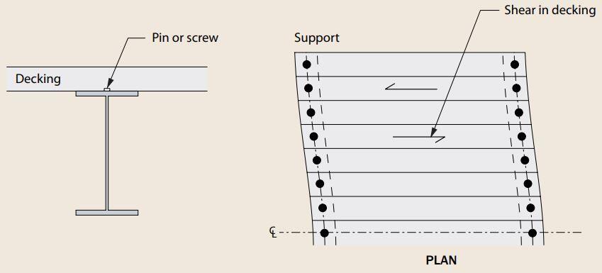
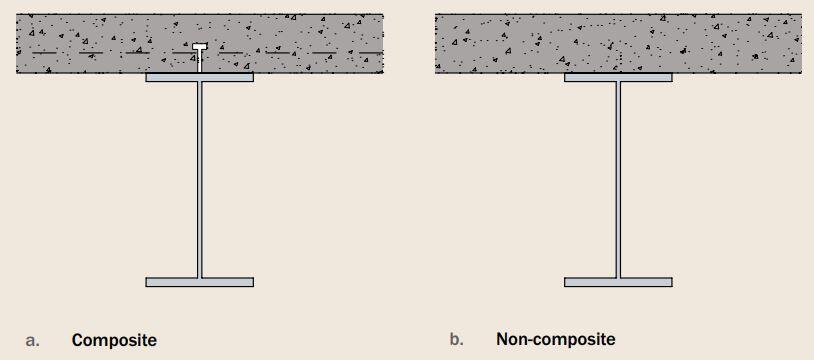
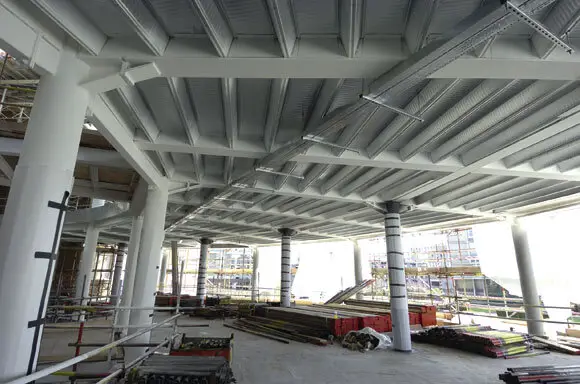
Composite slab with profiled metal decking provides economical solutions for floors of steel framed building systems. This is because they are easier to install, lighter in weight, and faster to execute when compared with precast, prestressed, and solid slab system for steel-framed buildings. The composite action of this floor system is achieved by welding steel studs to the top flange of the steel beams and embedding the studs in the concrete during concrete pouring.

Composite construction reduces frame loadings and results in a cheaper foundation system. Cold-formed thin-walled profiled steel decking sheets with embossments on top flanges and webs are widely used as the profiles. The use of this profiled metal decking eliminates the need for mat reinforcement in the slab and acts as the permanent shuttering for the concrete. Props are therefore not usually required during the process of concreting. This support scheme is usually suitable for spans that are less than 4m (spacing of the supporting beams). The supporting beams themselves can, however, span up to 12m.

Components of steel deck floor
metal profle decking

Structural engineers usually rely on load/span tables produced by metal deck manufacturers in order to determine the thickness of slab and mesh reinforcement required for a given floor arrangement, fire rating, method of construction, etc. The table below shows an example of a typical load/span table available from one supplier of metal decking.

t60
profile metal decking sheet

To download the full SMD technical data sheet for different types of profiled metal decking, click below.

Once the composite slab has been designed, the design of the primary and secondary composite beams (i.e. steel beams plus slab) can begin. This is normally carried out in accordance with the recommendations in Part 3: Section 3.1 of BS 5950. In Europe, composite sections are designed according to the requirements of Eurocode 4 (EN 1994 – 1- 1).

The steps in the design of profile metal decking for composite floors are;

  1. Determine the effective breadth of the concrete slab.
  2. Calculate the moment capacity of the section.
  3. Evaluate the shear capacity of the section.
  4. Design the shear connectors.
  5. Assess the longitudinal shear capacity of the section.
  6. Check deflection.

Design Example

The figure below shows a part plan of a composite floor. The slab is to be constructed using profiled metal decking and normal weight, grade 30 concrete. The longitudinal beams are of grade S275 steel with a span of 7.5 m and spaced 3 m apart. Design the composite slab and verify the suitability of 406 x 178 x 67  UKB as the internal beams. The required fire-resistance is 1 hour.

composite floor general arrangement

Imposed load = 4 kN/m2
Partition load = 1 kN/m2
Weight of finishes = 1.2 kN/m2
Weight of ceiling and services = 1 kN/m2
Total applied load = 7.2 kN/m2 (to be used for slab design i.e. selection from manufacturer’s span-load table)

SLAB DESIGN
From the span-load table above, the configuration below will be satisfactory for the unpropped slab.

Beam span = 7.5 m
Beam spacing = 3.0 m
Total depth of slab hs = 130 mm
Depth of profile hp = 60 mm
Overall height of profile hd = 72 mm
Depth of concrete above profile = 58 mm
Profile: SMD TR60+ (1.2 mm gauge)
Gauge = 1.2 mm
Mesh: A142

profile
Typical SMD TR60+ profile

From the manufacturer’s technical data sheet;
Volume of concrete = 0.096 m3/m2
Weight of concrete (wet) = 2.26 kN/m2
Weight of concrete (dry) = 2.21 kN/m2
Weight of profile = 0.131 kN/m2
Height to neutral axis = 33 mm

Shear connector
Connector diameter d = 19 mm
Overall welded height of hsc = 95 mm
Ultimate tensile strength fu = 450 N/mm2

Concrete
Normal weight C25/30 concrete
Cylinder trength fck = 25 N/mm2
Cube strength fck,cube = 30 N/mm2
Secant modulus of elasticity Ecm = 31 kN/mm2

Actions at Construction Stage

Permanent Actions
Self weight of sheeting = 0.131 kN/m2 x 3 m = 0.393 kN/m
Allowance for beam self-weight = 1.0 kN/m
Allowance for mesh = 0.05 kN/m2 x 3m = 0.15 kN/m
Total gk = 0.393 + 1 + 0.15 = 1.543 kN/m

Variable Actions
Self-weight of fresh concrete = 2.26 kN/m2 x 3m = 6.78 kN/m (note that fresh concrete is treated as variable action in the construction stage)
Construction load = 0.75 kN/m2 x 3m = 2.25 kN/m
Total qk = 6.78 + 2.25 = 9.03 kN/m

At ultimate limit state = 1.35gk + 1.5qk = 1.35(1.543) + 1.5(9.03) = 15.63 kN/m

Design moment MEd = ql2/8 = (15.63 x 7.52)/8 = 109.898 kNm
Design shear force VEd = ql/2 = (15.63 x 7.5)/2 = 58.61 kN

Actions at the composite stage

Permanent Actions
Self weight of sheeting = 0.131 kN/m2 x 3 m = 0.393 kN/m
Allowance for beam self-weight = 1.0 kN/m
Allowance for mesh = 0.05 kN/m2 x 3m = 0.15 kN/m
Self-weight of dry concrete = 2.21 kN/m2 x 3m = 6.63 kN/m
Weight of finishes = 1.2 kN/m2
Weight of ceiling and services = 1 kN/m2
Total gk = 0.393 + 1 + 0.15 + 6.63 + 1.2 + 1 = 10.373 kN/m

Variable Actions
Imposed load on floor = 4 kN/m2 x 3m = 12 kN/m
Movable partition allowance = 1 kN/m2 x 3m = 3 kN/m
Total qk = 12 + 3 = 15 kN/m

At ultimate limit state = 1.35gk + 1.5qk = 1.35(10.373) + 1.5(15) = 36.5 kN/m

Design moment MEd = ql2/8 = (36.5 x 7.52)/8 = 256.6 kNm
Design shear force VEd = ql/2 = (36.5 x 7.5)/2 = 136.875 kN

An advanced UK beam S275 is to be used for this design.
Fy = 275 N/mm2
γm0 = 1.0 (Clause 6.1(1) NA 2.15 BS EN 1993-1- 1:2005)

fa

From steel tables, the properties of 406 x 178 x 67  UKB are;

Depth h = 409.4 mm
Width b = 178.8 mm
Web thickness tw = 8.8mm
Flange thickness tf = 14.3 mm
Root radius r = 10.2 mm
Depth between fillets d = 360.4 mm
Second moment of area y axis Iy = 24300 cm4
Elastic modulus Wel,y = 1190 cm3
Plastic modulus Wpl,y = 1350 cm3
Area of section A = 85.5 cm2
Height of web hw = h – 2tf = 380.8 mm
Es (Modulus of elasticity) = 210000 N/mm(Clause 3.2.6(1))

Check out also ….
Design of Steel Beams to BS 5950 – 1: 2000
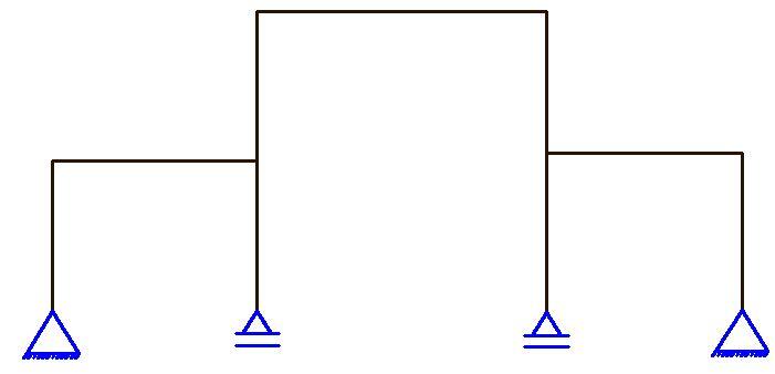
Structural Analysis of Compound Arch-Frame Structure

Classification of section

ε = √(235/Fy) = √(235/275) = 0.92 (Table 5.2 BS EN 1993-1- 1:2005)

Outstand flange
Flange under uniform compression c = (b – tw – 2r)/2 = [178.8 – 8.8 – 2(10.2)]/2 = 74.8 mm

c/tf = 74.8/14.3 = 5.23

The limiting value for class 1 is c/tf  ≤ 9ε = 9 × 0.92
5.23 < 8.28
Therefore, outstand flange in compression is class 1

Internal Compression Part (Web under pure bending)
c = d = 360.4 mm
c/tw = 360.4/8.8 = 40.954

The limiting value for class 1 is c/tw ≤ 72ε = 72 × 0.92 = 66.24
40.954 < 66.24
Therefore, the web is plastic. Therefore, the entire section is class 1 plastic.

Member Resistance Verification – Construction Stage

Moment Resistance
For the structure under consideration, the maximum bending moment occurs where the shear force is zero. Therefore, the bending moment does not need to be reduced for the presence of shear force (clause 6.2.8(2))

MEd/Mc,Rd ≤  1.0 (clause 6.2.5(1))

Mc,Rd = Mpl,Rd = (Mpl,y × Fy)/γm0

Mc,Rd = Mpl,Rd = [(1350 × 275)/1.0] × 10-3 = 371.25 kNm

At the construction stage;
MEd/Mc,Rd = 109.898/371.25 = 0.296 < 1.0 Ok

Shear Resistance (clause 6.6.2)
The basic design requirement is;

VEd/Vc,Rd ≤  1.0

Vc,Rd = Vpl,Rd = Av(F/ √3)/γm0 (for class 1 sections)
For rolled I-section with shear parallel to the web, the shear area is;

Av = A – 2btf + (tw + 2r)tf (for class 1 sections) but not less than ηhwtw

Av = (85.5 × 10² – (2 × 178.8 × 14.3) + [8.8 + 2(10.2)] × 14.3 = 3854 mm2
η = 1.0 (conservative)
ηhwt= (1.0 × 380.8 × 8.8) = 3351.04 mm2
3854 > 3351.04
Therefore, Av = 3854 mm2

The shear resistance is therefore;
Vc,Rd = Vpl,Rd = [3854 × (275/ √3)/1.0]  × 10-3 = 612 kN

At the construction stage;
VEd/Vc,Rd = 58.61/612 = 0.095 < 1.0 Ok

Shear Buckling
Shear buckling of the unstiffnened web will not need to be considered if;

hw/t≤  72ε/η

hw/t= 380.8/8.8 = 43.27
72ε/η  = (72 ×  0.92)/1.0  = 66

43.27 < 66 Therefore shear buckling need not be considered.

kw1

Design Resistance of Shear Connectors

Shear connector in a solid slab
The design resistance of a single headed shear connector in a solid concrete slab automatically welded in accordance with BS EN 14555 should be determined as the smaller of;

PRd = (0.8 x fu x π x 0.25d2)/γv (Clause 6.6.3.1(1) Equ(6.18) or
PRd = [0.29 x α x d2 x √(fck x Ecm)]/γv

Where;
α = 1.0 as hsc/d = 95/19 > 4 (Equation 6.21)

PRd = (0.8 x 450 x π x 0.25 x 192)/1.25 = 81.7 kN
PRd = [0.29 x 1.0 x 192 x √(25 x 31 x 103)]/1.25 = 73.7 kN

Shear connectors in profiled steel sheeting

For profiled sheeting with ribs running transverse to the supporting beams, PRd,solid should be multiplied by the following reduction factor;

kt = (0.7/√nr) x (b0/hp) x (hsc/hp – 1)

shear connector things

b0 = width of a trapezoidal rib at mid height of the profile = (133 + 175)/2 = 154 mm
hsc = 95 mm
hp = 60 mm
nr = 1.0 (for one shear connector per rib)

kt = (0.7/√1.0) x (154/60) x (95/60 – 1) = 1.0

Therefore PRd = ktPRd,solid = 1.0 x 73.7 = 73.7 kN
The design resistance per rib = nrPRd = 1 x 73.7 = 73.7 kN

Degree of shear connection

For composite beams in buildings, the headed shear connectors may be considered as ductile when the minimum degree of shear connection given in clause 6.6.1.2 is achieved.

For headed shear connectors with;
hsc ≥ 4d and 16mm ≤ d ≤ 25 mm

The degree of shear connection may be determined from;

η = Nc/Nc,f

Where;
Nc is the reduced value of the compressive force in the concrete flange (i.e. force transferred by the shear connectors)
Nc,f is the compressive force in the concrete flange at full shear connection (i.e. the minimum of the axial resistance of the concrete and the axial resistance of the steel)

For steel sections with equal flanges and Le < 25 m;

η ≥ 1 – (355/fy) x (0.75 – 0.03Le) where ≥ 0.4
Le = distance between points of zero moment = 7.5 m
η ≥ 1 – (355/275) x (0.75 – 0.03 x 7.5) = 0.322, therefore η = 0.4

Degree of shear connection present

To determine the degree of shear connection present in the beam, the axial resistances of the steel and concrete are required (Npl,a and Nc,f respectively)

stress block for calculating resistances of composite sections
Stress block for calculating the resistances of concrete sections

Determine the effective width of the concrete flange

At the mid-span, the effective width of the concrete falnge is;

beff = b0 + ∑bei

Composite section effective width dimensions
Effective flange width of composite section

For nr = 1.0, b0 = 0 mm
bei = Le/8 but ot greater than bi

Le = 7.5 m (point of zero moment)
bi = distance from the outside shear connector to a point between adjacent webs. Therefore;

b1 = b2 = 1.5 m
be1 = be2 = Le/8 = 7.5/8 = 0.9375 m

The effective flange width is therefore
beff = b0 + be1 + be2 = 0 + 0.9375 + 0.9375 = 1.875 m = 1875 mm

Compressive resistance of the concrete flange

The design strength of the concrete fcd = 25/1.5 = 16.7 N/mm2

The TR60+ profile has a 12 mm deep re-entrant above the stiffener making the overall profile depth hd = 12 mm + 60 mm = 72 mm

The compressive resistance of the concrete flange is therefore;
Nc,f = 0.85fcdbeffhc = 0.85 x 16.7 x 1875 x 58 x 10-3 = 1543.7 kN

Tensile Resistance of the steel member
Npl,a = fy.A = 275 x 85.5 x 102 x 10-3 = 2351.25 kN

The compressive force in the concrete at full shear connection is the lesser. Therefore Nc = 1543.7 kN

Resistance of the shear connectors

n is the number of shear connectors present to the point of maximum bending moment. In this example, there are 7.5(2 x 0.333) = 12 ribs available for positioning shear connectors per half span.

Nc = n x PRd = 12 x 73.7 = 884.4 kN

The degree of shear connection present therefore is;

η = Nc/Nc,f = 884.4/1543.7 = 0.572 > 0.40 (Okay)

Design Resistance of the Cross-section at the composite stage

Bending Resistance

According to clause 6.2.1.2, the plastic rigid theory may be used for one connector per trough. With partial shear connection, the axial force in the concrete flange Nc is less than Npl,a (884.4 kN < 2351.25 kN). Therefore, the plastic neutral axis lies within the steel section. Assuming that the plastic neutral axis lies a distance xpl below the top of the flange of the section, where;

xpl = (Npl,a – Nc)/2fyb = (2351.25 – 884.4)/(2 x 275 x 178.8) = 0.0149 m = 14.916 mm > tf (14.3 mm)

Therefore the plastic neutral axis lies below the top flange.

stress block distribution
Stress block of composite cross-section

yc = Nc/[0.85fckbeff /γc] ≤ hc
yc = (884.4 x 1000)/[0.85 x 25 x 1875/1.5] = 33.28 mm

MRd  = Nc(hc + da – yc/2) + 2btffy(da – tf/2) + tw(ya – tf)(fy)(2da – ya – tf)
MRd  = (884.4 x 103) x (130 + 204.7 – 33.28/2) + 2 x 178.8 x 14.3 x 275 x (204.7 – 14.3/2) + 8.8(14.92 – 14.3) x 275 x (2 x 204.7 – 14.92 – 14.3) = 559669744.2 Nmm = 559.669 kNm

MEd = 256.6 kNm

MEd/MRd = 256.6/559.669 = 0.458 < 1.0 (Okay)

Shear Resistance at the Composite Stage

The shear resistance is therefore;
Vc,Rd = Vpl,Rd = [3854 × (275/ √3)/1.0]  × 10-3 = 612 kN
VEd = 136.875 kN
VEd/Vc,Rd = 136.875/612 = 0.223 < 1.0 Ok

Longitudinal shear resistance of the slab

Crack control
Crack control mesh as transverse reinforcement

Neglecting the contribution of the steel, we ned to verify that;

Asffsd/Sf > vEdhf/cotθ

Where;
vEd is the design longitudinal shear stress in the concrete slab
fsd is the design yield strength of the reinforcing mesh = 0.87fyk = 0.87 x 500 = 434.8 N/mm2
hf = depth of the concrete above the profiled sheeting = 70 mm
θ angle of failure (try 26.5o)
Asf/Sf = At (for the plane of failure shown as section a-a)
At is the cross-sectional area of transverse reinforcement mm2/m)

The verification equation therefore becomes;

Atfyd > vEdhf/cotθ

The required area of tensile reinforcement At must satisfy the following;

At > vEdhf/fydcotθ

The longitudinal shear stress is given by;

vEd = ∆Fd/hf∆x

Where;
∆x is the critical length under consideration, which is usually taken as the distance between the maximum bending moment and the support = L/2 = 7.5/2 = 3.75m
∆Fd = Nc/2 = 884.4/2 = 442.2 kN

vEd = ∆Fd/hf∆x = (442.2 x 10³)/(70 x 3750) = 1.68 N/mm2

vEdhf/fydcotθ = (1.68 x 70)/(434.8 x cot 26.5o) = 0.134 mm2/mm

For the arrangement, the area of tensile reinforcement required is 134 mm2/m
Therefore A142 mesh provided is adequate (Asprov = 142 mm2/m)

Crushing of the concrete flange

It is important to verify that
vEd < vfcdsinθfcosθf
v = 0.6(1 – fck/250) = 0.6 x (1 – 25/250) = 0.54
vfcdsinθfcosθf = 0.54 x 16.67 x sin(26.5) x cos(26.5) = 3.59 N/mm2

(vEd) 1.68 N/mm2 < 3.59 N/mm2 (Okay)

Serviceability limit state

Modular ratios
For short term loading, the secant modulus of elasticity should be used. Ecm = 31 kN/mm2. This corresponds to a modular ratio of;

n0 = Es/Ecm = 210/31 = 6.77 (clause 5.4.2.2)

For long term loading;
nL = n0(1 + ψLϕt)
Where ψL is the creep multiplier taken as 1.1 for permanent loads and ϕt is the creep coefficient taken as 3.0.
nL = 6.77 x (1 + 1.1 x 3) = 29.11

When calculating deflection due to variable action, the modular ratio is taken as;

n = 0.333nL + 0.667n0 = 0.333(29.11) + 0.667(6.77) = 14.22

Since the beam is simply supported, use the gross value of second moment of area, Ic, of the uncracked section to calculate deflection.

Ic = Iy + [beff(hs – hp)3/12∙ni] + [A∙beff(hs – hp)(h + hs + hp)2]/4[A∙ni + beff(hs – hp)]

For n0 = 6.77
Ic = 24300 x 104 + [1875(130 – 60)3/(12 x 6.77)] + [85.5 x 102 x 1875(130 – 60) x (409.4 + 130 + 60)2]/4[85.5 x 102 x 6.77 + 1875(130 – 60)] = 78385 x 104 mm4

For nL = 29.11
Ic = 24300 x 104 + [1875(130 – 60)3/(12 x 29.11)] + [85.5 x 102 x 1875(130 – 60) x (409.4 + 130 + 60)2]/4[85.5 x 102 x 29.11 + 1875(130 – 60)] = 50999 x 104 mm4

For n = 14.22
Ic = 24300 x 104 + [1875(130 – 60)3/(12 x 14.22)] + [85.5 x 102 x 1875(130 – 60) x (409.4 + 130 + 60)2]/4[85.5 x 102 x 14.22 + 1875(130 – 60)] = 64543 x 104 mm4

Deflection due to actions on the steel at the construction stage;
Actions = self weight of fresh concrete + mesh + sheeting + steel section
w1 = 5gl4/384EI = (5 × 8.323 × 75004)/(384 × 210000 × 24300 × 104) = 6.719 mm

Deflection due to permanent action on the steel at the composite stage;
Actions = weight of finishes + ceiling and services
w2 = 5gl4/384EI = (5 × 6.6 × 75004)/(384 × 210000 × 50999 x 104) = 2.54 mm

Deflection due to variable action on the steel at the composite stage;
Actions = Imposed load + partition allowance
w3 = 5ql4/384EI = (5 × 15 × 75004)/(384 × 210000 × 64543 x 104) = 4.559 mm

Total deflection = w1 + w2 + w3 = 6.719 + 2.54 + 4.559 = 13.818 mm

Allowable deflection = L/360 = 7500/360 = 20.833 mm.
13.818 < 20.833 Therefore deflection is okay.

Effects of Trees on Wind Comfort of Pedestrians

Pedestrian wind comfort can be improved when horizontally incoming airflow passes through trees in the urban areas. This is according to recent research carried out in the Department of Environmental Atmospheric Sciences, Pukyong National University, Busan, Republic of Korea, and published in Elsevier – Sustainable Cities and Societies. In the study, the authors applied computational fluid dynamics incorporating tree drag parameters to evaluate how trees improved the wind comfort of pedestrians.

The way wind is perceived at the ground level depends on a lot of factors such as wind direction, wind speed, obstacles, and many other parameters. This experience affects pedestrians’ comfort and safety, and can impact the financial returns or economic viability of an area. According to Lawson-based wind comfort criterion, wind speed exceeding 10 m/s can be uncomfortable for pedestrians at the ground level, while wind speed above 15 m/s is outrightly dangerous. Other wind comfort criteria exist such as that proposed by Davenport.

Trees are known to function as porous obstacles to airflow, and they eventually affect wind speed and direction. The presence of high rise buildings and urban densification has been observed to reduce airflow in city centers and may lead to increased urban heat and poor dispersal of pollutants. However, the effect of wind on tall buildings can amplify wind pressure in the surroundings due to issues like vortex shedding, reverse flow, channeling effects, etc. This can lead to discomforting wind effects on pedestrians. Therefore, by applying computational fluid dynamics model (CFD) with tree drag parameterization scheme, the researchers were able to evaluate the effect of trees on pedestrian wind comfort in Pukyong National University campus. The CFD model used in the study was verified with field observations.

The CFD model used in the study was based on Reynolds-averaged Navier–Stokes (RANS) equations and assumes a three-dimensional, non-rotating, non-hydrostatic, incompressible airflow system. Turbulence was parameterized using the renormalization group (RNG) k-ε turbulence closure scheme. Tree drag terms were introduced into the momentum, turbulent kinetic energy (TKE), and TKE dissipation rates equations to account for the loss of airflow pressure due to winds.

The target area for the research was the Pukyong National University (PKNU) campus (See Fig. 1a) which is located in the downtown area and is surrounded by commercial and residential areas. PKNU boasts relatively high vegetation density for student recreational spaces and ecologically friendly landscaping within the campus. Regions A and B (Fig. 1b) contains a dense forest of trees taller than 10–15 m. Several tree species are planted along the PKNU boundary (region C in Fig. 1b).

Target area
Fig. 1. Aerial photograph of (a) the target area, including Pukyong National University campus (from www.daum.net) and (b) high-density vegetation regions (A, B,
and C in Fig. 1a) (from www.pknu.ac.kr). The red dot in (a) indicates the location of automated weather station (AWS) 942. (Kang et al, 2020)

The authors adopted the wind comfort criteria proposed by Isyumov and Davenport (1975), which distinguish four sensory levels (good, tolerable, unpleasant, and dangerous) for four categories of human activity or activity location (Table 1). These sensory levels are determined by the Beaufort wind force scale (BWS), represented by wind speeds at 10 m above the ground level. To evaluate wind comfort at the pedestrian level (z =1.75 m), they used the BWS values converted into pedestrian height.

Table 1: Sensory levels in terms of suitability for outdoor activities, represented by the Beaufort wind force scale (BWS) (Isyumov & Davenport, 1975).

Davenport wind comfort criteria

From the study, poor wind comfort for outdoor activities (BWSs ≥ 4) was observed in the areas without trees, mainly around the edges of buildings, in the windward regions of buildings, in the spaces between buildings, and in wide, unobstructed areas. This was attributed to venturi effects between the spaces in buildings. In the case of where trees were present, the BWS values declined by one to three levels, improving the overall level of wind comfort within the PKNU campus.

The highest ABWS and TBWS values (≥ 4) were observed near the southeast perimeter of the PKNU campus, where a 10-lane road is located. By contrast, the lowest ABWS and TBWS values (≤ 3) were observed in the southwest and northwest of the campus. Where trees were present, the overall wind speeds inside the campus were reduced due to drag.

The authors concluded that tree arrangement can reduce wind speeds in the lee of the trees by more than half and proposed that trees should be planted at 90° to the dominant wind direction. The presence of trees decrease wind speeds. However, because wind speeds can increase in surrounding areas without trees, the effects of trees on strong winds in such areas should be assessed.

Reference
Kang G., Kim J., Choi W. (2020): Computational fluid dynamics simulation of tree effects on pedestrian wind comfort in an urban area. Sustainable Cities and Societies 56 (2020)102086. https://doi.org/10.1016/j.scs.2020.102086

Disclaimer:
Contents of this research article have been shown on www.structville.com because it is an open access article under creative commons licence (http://creativecommons.org/licenses/BY/4.0). All other rights belong to the authors and Elsevier.

Difference Between Pile Load Test and Pile Integrity Test

Pile foundations are slender structures used to transmit superstructure load to firmer sub-soil stratum beneath the natural ground surface. They can also be used for other purposes such as resisting heavy lateral forces, compaction of soils (compaction piles), avoiding excessive settlement, etc. Due to their importance in civil engineering structures, piles are usually subjected to tests such as pile load tests and pile integrity tests before they are loaded. These two tests are completely different and are sometimes confused for one another, even though they do not serve the same purpose. This article aims to highlight the difference between these two tests.

Read Also …
Design of pile foundation using pile load test (Eurocode 7)
3D Soil-structure interaction of cantilever retaining walls

Pile Load Test

Pile load test
Static pile load test set up

Generically, pile load test can be described as a reliable method of pile foundation design which involves loading constructed piles on-site to determine their load-carrying capacity. A pile load test involves applying increments of static loads to a test pile and measuring the settlement. The load is usually jacked onto the pile using either a large deadweight or a beam connected to two uplift anchor piles to supply reaction for the jack. Generally, an installed pile, weights, deflection gauge, hydraulic jack, and load indicator are required for a pile load test.

Loading of test piles is usually applied in increments of 25% of the total test load which should be 200% of the proposed design load. After the load test, the load-settlement curve is plotted and the failure load determined. Eurocode 7 permits three different methods for the design of pile foundations which are;

  • By testing (static load test, ground testing result, dynamic ground testing)
  • By calculation (empirical or analytical)
  • By observation

It is important that the validity of static load test be checked using calculations.

Pile Integrity Test

pile integrity test
Pile Integrity Test setup

Pile integrity test (PIT) is a non-destructive method of testing of piles that is used for qualitative evaluation of the physical dimensions, continuity, and consistency of materials in a bored (cast in-situ) pile. This test is very important for quality control and quality assurance of piles at great depth.

The three most common methods of carrying out pile integrity tests are;

  • Low-strain pile integrity test
  • Crosshole sonic logging
  • Thermal integrity test

In the low-strain impact integrity testing, the head of the pile shaft is subjected to impact using a tool like a simple hammer and the response is determined using a high precision transducer. The transducer can either be an accelerator, or a velocity sensor. Low-strain pile integrity tests can provide information such as embedment length, changes in cross-section (such as bulging), discontinuity (such as voids), and consistency of pile materials (such as soil inclusion and segregation). However, it cannot provide information such as bearing capacity and cannot be applied to pile caps.

Differences and similarities between pile load test and pile integrity test at a glance

Pile Load TestPile Integrity Test
Used for determining bearing capacity of pilesUsed for determining physical properties of constructed piles
Can evaluate pile settlement under loadCannot evaluate pile settlement
Expensive to set upCost effective
Takes time to completeVery quick test
Cannot provide the embedment length of the pileProvides embedment length of the pile
Cannot give information on the quality of the piling jobProvides information on the quality of the piling job

Therefore, pile load test and pile integrity tests should be carried out as soon as piling jobs are concluded on site before the next stage of the construction commences.

Design of Pile Cap Using Staad Foundation Advanced

Pile caps are rigid plate structures that are used to transfer superstructure load from columns to a group of piles. They are usually subjected to bending and shear forces, and shear considerations usually govern the thickness design of pile caps. The three main approaches that are used in the analysis of pile caps are;

  • Truss Analogy
  • Bending analogy, and
  • Finite element analysis

While truss analogy and bending theory can be easily carried using quick manual calculations, finite element analysis usually require the use of computer models. In this article, we are going to explore the potentials of Staad Foundation Advanced Software in the analysis and design of pile caps.

Read Also…
Design of pile foundation system for bridge piers
Structural Aspects of Pile Foundation Design

A quick design of pile caps can be done on Staad Foundation Advanced using the Foundation Toolkit option. This approach does not require importing models and can be used for quick stand-alone design when the column load and geotechnical parameters of the soil are available. To use this option, launch the ‘Staad Foundation Advanced‘, click on ‘New Project‘, and select ‘Foundation Toolkit‘ labelled as shown below.

Step 1: Launch the foundation toolkit

foundation tool kit

Step 2: Create Pile Cap Job

When the Foundation Toolkit opens, go to ‘Main Navigator‘, and from ‘Project Info‘ drawdown list, select ‘Create Pile Cap Job‘ as shown below.

pile cap job 1

Step 3: Select design code, units, and pile layout

When the ‘Pile Cap Job’ is launched, select the desired code of practice, unit, and click ‘Next’. The pile layout can be left as predefined.

input wizard

Step 4: Define the load

On clicking ‘Next’, the dialog box for load comes up. Make sure that the unit is consistent as desired, and for this exercise, I am applying a factored column load of 3500 kN. If there are other forces such as moment and shear coming from the column, you can define them also.

Load

Step 5: Define Load Combination

Since we are dealing with an already factored load, select ‘User Defined‘ from the drawdown list of load combination. If you have defined dead load, live load, wind load etc in Step 4, you can select the desired code of practice for the combination of the loads. Since I defined my factored load as dead load, I assigned a factor of 1.0 to dead load at ULS and SLS (actually I am not interested in SLS in this design). Then click ‘Next

Load combination

Step 6: Define the design parameters

In this case, the column dimensions are taken as 450 mm x 450 mm, and the thickness of the pile cap was taken as 1300 mm. Other design parameters specified are as shown below.

Design parameters

Read Also…
Manual Design of Beam and Raft Foundation
Solved Example on Elastic Settlement of Shallow Foundations

Step 7: Select pile arrangement

The diameter of the pile was selected as 750 mm, with a spacing of 2250 mm. The safe working load of the pile was taken as 900 kN. You can also input the uplift and lateral load capacity of the pile. The edge distance is taken as (diameter of pile/2 + 150 mm) – where 150 mm is the overhang from the edge of the pile to the edge of the pile cap. Then click on ‘Calculate‘.

pile arrangement 2

This brings the possible pile arrangements based on the safe working load and the superstructure load. For this tutorial, the arrangement below was adopted. The simple idea behind it is simply (Column load/pile safe working load). Note that for practical purposes, serviceability limit state load should be used when selecting the number of piles. Then click ‘Ok‘ and ‘Next‘.

22 1

Step 8: Finish the model

finish 1

Step 9: Carry out the Design

Clicking ‘Finish‘ returns you to the ‘Main Navigator‘ page, where you can click on ‘Design‘ to carry out the design of the pile cap.

design

Step 10: View the output

The output page is where you can view the geometry drawing, details and schedule drawing, calculation sheet, and graphs.

output

The design approved the 1300 mm thick pile cap provided, and provided Y16@100 mm c/c reinforcement. You can go ahead and print the calculation sheet which you can download below.

Thank you for visiting Structville Today, and God Bless You

Modeling of Soils Using Isogeometric Analysis

Researchers from the Department of Construction Sciences, Lund University, Sweden have presented isogeometric analysis as an alternative to finite element analysis for modelling of soil plasticity. In a study published in the year 2017 in Geomaterials Journal, the researchers were able to show that isogeometric analysis showed good agreement with finite element method for drained soils in two- and three-dimensions. The research, therefore, suggested that isogeometric analysis is a good alternative to conventional finite element analysis for simulations of soil behavior.

Isogeometric analysis is a numerical method that uses non-uniform rational B-splines (NURBS) as basis functions instead of the Lagrangian polynomials often used in the finite element method. These functions have a higher-order of continuity and therefore makes it possible to represent complex geometries exactly. The basic idea behind isogeometric analysis is to use splines (NURBS) as basis functions for computational analysis by applying them directly. This allows the same basis function to be used for discretzation and for analysis.

A1 1
Representation of quadratic B-spline basis function with knot vector Ξ = {0, 0, 0, 1, 2, 3, 4, 5, 5, 5} (Spetz et al, 2017)
A2 2
Representation of quadratic Lagrangian basis function (Spetz et al, 2017)

Since being introduced by Thomas J.R. Hughes at the University of Austin, Texas in the year 2005, isogeometric analysis has found numerous applications in engineering such as analysis of thin plates and shells, soil-structure interaction, fluid-structure interaction, flow through porous media, etc. However, finite element analysis has been used extensively for constitutive modelling of soils for the design of foundations, retaining walls, slope stability problems etc.

For the purpose of the research, Drucker-Prager criterion and the theory of plasticity was used by the researchers to evaluate the influence of the NURBS-basis functions on the plastic strains for granular materials against the conventional finite element analysis approach.

To compare the results of the findings, a 2D model of a strip footing on sandy silt was analyzed. The problem was solved for plane strain conditions using quadratic NURBS based IGA and conventional FEA with 5 different meshes. In order to compare the two methods, the element meshes were constructed using quadratic isoparametric elements for both IGA and conventional FEA.

k11
Load/displacement response at point A and B for the finest mesh (4800 elements) (Spetz et al, 2017)

The first point, A, denotes the center of the footing and the second point, B denotes the edge of the footing. It was observed that the displacements in the model are in good agreement at center of the footing but a minor difference was observed between the displacements from the isogeometric and conventional finite element analysis at the edge of the footing.

References
Spetz, A. , Tudisco, E. , Denzer, R. and Dahlblom, O. (2017): Isogeometric Analysis of Soil Plasticity. Geomaterials7, 96-116. doi: 10.4236/gm.2017.73008.

Featured Image: Institute for Structural Mechanics, University of Stuttgart. https://www.ibb.uni-stuttgart.de/en/research/shells-fem-iga/

Disclaimer:
This research article has been featured on www.structville.com because it is an open access article that permits unrestricted use and distribution provided the original source of the article has been cited. See the Creative Commons Attribution International License (CC BY 4.0). http://creativecommons.org/licenses/by/4.0/

Free Vibration of Masts

Tall masts are used in a variety of applications such as telecommunication, radio/television broadcasting, supporting lighting fixtures on the highway, raising flags, etc. Due to their height above the ground, these structures are usually subjected to wind action, and this makes the knowledge of their behavior under the effect of wind very important.

The dynamic behavior of telecommunication masts under the effect of wind is studied under ‘flow-induced vibration of structures’. This term is used to denote the phenomena associated with the response of a structure immersed in or conveying fluid flow. It covers those cases in which an interaction develops between fluid dynamic forces and the inertia, damping, or elastic forces in the structure. The study of these phenomena draws on three disciplines which are, structural mechanics, mechanical vibration, and fluid dynamics (Ahmad, 2009).

Read Also …
Effects of wind on different configurations of telecommunication mast
Design of Roof Purlins

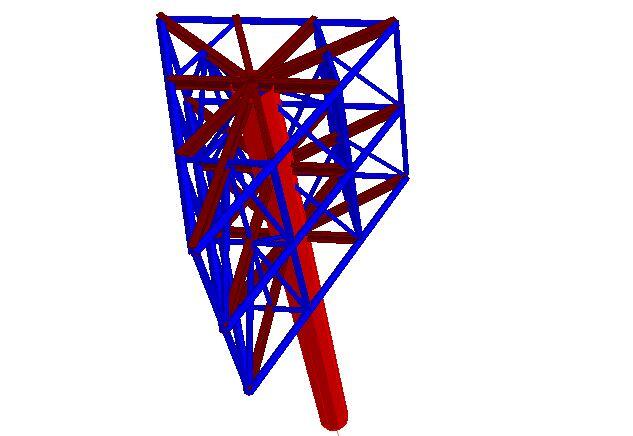
This article investigates the natural frequency of vibration of X-braced and V-braced (Chevron bracing) telecommunication masts. To advance the study, the wind-induced vibration can be investigated using Staad Pro software (finite element analysis) in order to determine the critical wind speed that will potentially lead to resonance in the structure under the effect of wind. Resonance occurs when one of the natural frequencies of the structure coincides with the frequency of the vortices shedding around the mast due to the effect of wind.

Methodology

To carry out this study, two models of telecommunication masts were considered;

MODEL 1

A4 1

Type: X-Bracing
Height: 30 m
Width at the base: 3m x 3m
Width at the top: 1m x 1m
Section of the legs: UA 100 x 100 x 8
Section of the horizontal bracings and diagonals: UA 50 x 50 x 6
Solidity ratio: 20.6%

A2 1

The first four fundamental natural frequencies of the structure were obtained as follows;

ModeFrequency (Hz)Period (Sec)MPF-X (%)MPF-Y (%)MPF-Z (%)
12.6370.37932.3030.00024.153
22.6370.37924.1530.00032.303
311.5680.08613.0730.0009.760
411.5680.0869.7600.00013.073
Table 1: Natural frequency of x-braced telecom masts

N/B: MPF – Mass participation factor

2b
2nd mode of vibration of x-braced mast
2C
3rd mode of vibration of x-braced mast

Have some time?
Take a quiz on THEORY OF STRUCTURES

MODEL 2

B4

Type: V-Bracing (Chevron Bracing)
Height: 30 m
Width at the base: 3m x 3m
Width at the top: 1m x 1m
Section of the legs: UA 100 x 100 x 8
Section of the horizontal bracings and diagonals: UA 50 x 50 x 6
Solidity ratio: 19.51 %

B2

The first four fundamental natural frequency of the structure were obtained as follows;

ModeFrequency (Hz)Period (Sec)MPF-X (%)MPF-Y (%)MPF-Z (%)
12.7750.36026.1530.00030.132
22.7750.36030.1320.00026.153
311.3900.0889.0210.00014.375
411.3900.08814.3750.0009.021
Table 2: Natural frequency of v-braced telecom masts

N/B: MPF – Mass participation factor

mode 2a
2nd mode of vibration of v-braced (chevron) mast
mode 3a
3rd mode of vibration of v-braced (chevron) mast

Time history analysis can be used to evaluate the response of the mast to periodic vortex shedding excitations. It is a step-by-step analysis that involves solving the dynamic equilibrium equations given by;

Kx(t) + Cẋ(t) + Ṁẍ(t) = r(t) (1)

Where,

K  is the stiffness matrix
C is the proportional damping matrix
is the diagonal mass matrix
x is the relative displacements with respect to the ground
is the relative velocities with respect to the ground
is the relative accelerations with respect to the ground
r is the vector of the applied load.
t is time

The load r(t) applied in a given Time-History analysis may be an arbitrary function of space and time. It can be written as a finite sum of spatial load vectors multiplied by time function. The frequency of vortex shedding (fv) is related to the Strouhal number (S) and the relationship is given by;

S = fvW/U —— (2)

Where W is the average outside width of the mast (m). The value of ݂fv is calculated for different values of velocities. The velocity values chosen should result in Reynolds number (Re) values that still fall in ranges of constant Strouhal number S = 0.21 for low speeds and 300 < ܴ݁Re < 2 x 10⁶ or ܵS = 0.27 for high speeds and ܴ݁Re > 3.5 x 10⁶.

From equation (2) we can deduce that;

fv = SU/W ——- (2a)

For resonance to occur, note that fv = fs (where fs is the natural frequency of the structure)

Note that we can calculate the range of velocities based on Reynolds’s number. The Reynolds numbers that can be used for this purpose are 300, 2 x 10⁶ and 3.5 x 10⁶.

Re = UW/vair (3)

Where vair is the kinematic viscosity of flowing air (ν = 1.51 x 10⁻⁵ m2/s at standard atmospheric pressure and 20oC).

However, it should be noted that a latticed tower has a complex aerodynamic shape to the wind such that consistent vortex shedding to cause complete oscillation of the structure over a prolonged period is almost impossible. This is because the vortex shed from the different trussed members can rarely have a uniform frequency, thereby reducing the possibility of vortex-induced vibration. However, for towers with circular or tubular cross-section over the whole or part of its body, vortex-induced vibration is a possibility.

Effects of Wind on Telecom Masts

Telecommunication masts or towers are tall structures that are designed for the transmission of telecommunication signals or for radio/television broadcasting. Telecom masts are usually made of steel structures of which the members can be made of hot rolled angle sections or circular hollow tube sections. Due to their height above the ground, the effect of wind is quite significant in the design of telecom masts and may govern the structural design.

Telecom masts can collapse for a variety of reasons of which wind can be one of them. According to Balczo et al (2006),

There are very few cases where masts collapsed, and the reasons for them are in most cases not the wind forces which were taken according to the standard into consideration at stress analyses, but coincidence of other fatal circumstances. … Out of 225 mast failures in Europe only 7 were caused by wind overload. It is also thought-provoking that the wind-storm in 1999 in Denmark caused no collapse of any masts although a number of masts should have been crashed according to the stress analyses carried out by using Eurocode.

Read Also…
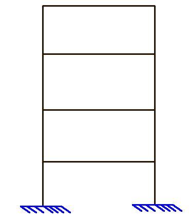
Structural stability of a braced ten-storey steel frame
How to apply wind load on high-rise buildings

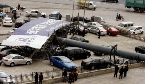
However, in Nigeria, a telecom mast was reported to have collapsed in Jalingo after a heavy storm in May 2018, which led to loss of lives. A similar incident was also reported in Edo State in the year 2018, after a heavy storm. However, no technical analysis was done to evaluate the cause of the collapse of the telecommunication masts.

failed telecom masts
Collapsed Telecom mast in Edo State, Nigeria (May, 2018)
telecom mast collapse 3
Collapsed telecom mast in Jalingo, Nigeria (May, 2018)

Different structural configurations can be adopted for telecom masts but it appears that the structural efficiency of all configurations is not the same. Therefore, this article aims to explore the effect of wind on different configurations of steel telecom masts.

In Europe, wind action on telecom mast can be evaluated according to the procedure described in EN 1991-1-4:2005 (Eurocode 1 Part 4) with emphasis on clause 7.11 of the code. In America, this can be evaluated according to the procedure described in ASCE-7 (2010).

In this article, the response of cross-bracing configuration (X-braced) and V-bracing structural configuration to wind load will be investigated using Staad Pro software and ASCE-7-2002.

The models used in the study are shown below.

Model 1: X-braced telecom masts

A4 1

Type: X-Bracing
Height: 30 m
Width at the base: 3m x 3m
Width at the top: 1m x 1m
Section of the legs: UA 100 x 100 x 8
Section of the horizontal bracings and diagonals: UA 50 x 50 x 6
Design wind speed: 50 m/s
Building classification category: II
Exposure category: Category B
Solidity ratio: 20.6 %

A2 1

The following results were obtained when analysed for self-weight and the effect of wind load.

A1

Maximum deflection at the top = 52.63 mm

The maximum internal forces are shown below;

k1

Model 2: V-braced telecom masts

B4

Type: V-Bracing
Height: 30 m
Width at the base: 3m x 3m
Width at the top: 1m x 1m
Section of the legs: UA 100 x 100 x 8
Section of the horizontal bracings and diagonals: UA 50 x 50 x 6
Design wind speed: 50 m/s
Building classification category: II
Exposure category: Category B
Solidity ratio: 19.51 %

B2

When analysed for the effect of wind, the result below was obtained;

B1

Maximum deflection at the top = 42.802 mm

The maximum internal forces are shown below;

k2

The table of comparison is shown below;

Action EffectX-BracingV-Bracing% Difference
Deflection (mm)52.6342.8018.67%
Maximum axial tension (kN)82.61565.88320.25 %
Maximum axial compression (kN)91.47874.09519.00%

From the table above, it can be seen that under the same conditions, V-braced masts perform better than X-braced masts under the effect of the wind.

When a lateral load is applied to an X-braced frame, the diagonal braces are subjected to compression while the horizontal web acts as the axial tension member in order to maintain the frame structure in equilibrium under lateral load. For V-braced frames (chevron bracing), one of the braces resists the tension while the other brace resists compression at each storey.

Both the tension and compression brace distribute the lateral load equally in the elastic range before the buckling point. However, the tension brace will remain in tension while the compression brace will lose all the axial load capacity after buckling. This contributes to the unbalanced distributed lateral load and can cause a large bending moment in the intersection of the beam and braces.

However, V-braced frames possess high elastic stiffness and strength when compared with X-braced frames.

Lapping of Reinforcements and Use of Rebar Couplers – Peculiarities and Differences

In reinforced concrete buildings, it is almost impossible to carry out construction without lapping reinforcements at one point or another. This is due to obvious reasons such as ease of transportation and handling. Also at very long lengths, reinforcements will become unstable under their own weight when placed in a vertical position. Lapping (reinforcement splicing) is the traditional way that has been used to join two different reinforcements during construction. However, in recent times, mechanical splices (such as rebar couplers) have been introduced to make two different pieces of reinforcements joined together to behave as ‘one continuous unit’.

The three general methods identified for reinforcement splicing are;

  • Lap splices
  • Welded splices, and
  • Mechanical splices

Read Also…
Detailing of columns to Eurocode 2

It is generally known that when reinforcements are lapped traditionally (lap splices), the two rebars will depend on the bond of the concrete for load transfer. However, with the use of mechanical splices concrete is not needed for load transfer since the two bars tend to behave as ‘continuous unit’. Furthermore, the idea of lapping is inherently wasteful and may lead to heavy congestion of reinforcement in a section of a concrete member. On the other hand, welding of bars is considered a more expensive alternative which may depend on the chemical properties of the reinforcing bar for adequate weldability.

detailing at laps
Lap region of a concrete column

The advantages of using mechanical splices over lap splices in reinforcements are;

(1) Enhanced Structural Performance

The structural integrity of joints connected with the use of mechanical splices is enhanced since the connection does not need to rely entirely on concrete bond for load transfer. In seismic applications, mechanical splices tend to maintain structural integrity when bars are stressed into the inelastic range. On the other hand, lap splices can infringe into the plastic hinge region, which is in violation of code limitations.

(2) Saves design effort

In reinforced concrete design, the engineer is expected to carry out calculation of lap length, which can depend on the size and type of the reinforcement, the grade of the concrete, the bond condition, and concrete cover. But with the use of mechanical splices, such computational effort is eliminated.

rbar
Rebars joined using mechanical couplers

(3) Savings in Materials

With the use of mechanical splices, reinforcement bars do not overlap, thereby leading to savings in materials.

(4) Reduction in bar congestion

Lapping of reinforcement effectively doubles the steel-to-concrete ratio, and the resulting congestion can make the placement and consolidation of concrete difficult. Furthermore, the code limits the area of reinforcement in lap regions of columns to 0.08Ac. Using rebar couplers completely eliminates this challenge.

A peculiar disadvantage of mechanical splices is the extra step of preparation of bars required before couplers are installed. A special care is needed in cutting the threads correctly and to protect the threads from corrosion before installing the couplers as these reasons could lead to improper fixing of couplers.

REBAR COUPLER
Typical threaded end of a rebar for coupling

However in a research carried out in Sri Lanka in the year 2018, the additional cost incurred in preparation of bars which includes the cost of two machineries (forging machine and thread cutting machine) and additional workmanship (one electrician and an unskilled labourer), seems to produce attractive cost benefits compared to lap splicing for larger diameter bars such as 32 mm and 40 mm.

rebar coupler 500x500 1

In a study to check the failure pattern of reinforcements joined using couplers, two failure modes were identified which are;

  • Failure of the rebar, and
  • Failure of connection

However, it was found that the failure stress of the bars which failed due to failure of connection is greater than the yield stress of steel and closer to the fracture point of steel. Due to the fact that the design stress of rebars is taken as the yield stress of steel and also due to the reduced stress in steel when steel are in contact with concrete, the risk of failure due to improper fixing of couplers may not be critical.