Floor loadings are loads applied to the floors of buildings such as slabs, decks, and pavements. All floors should be able to withstand the loads applied to them during their service life, and it is the duty of the structural engineer to ensure that the anticipated loading is adequately assessed, and accounted for during design.
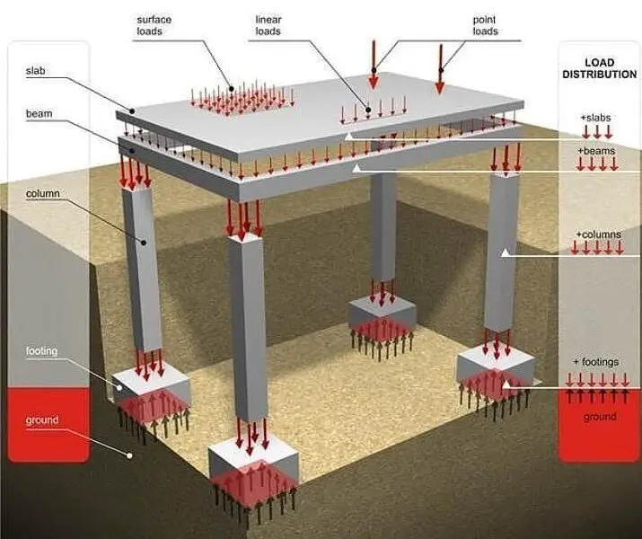
In a real sense, the loads applied to the floor of a building may be arbitrary and dynamic such as the self-weight of the floor and finishes, the weight of furniture, human occupancy, different kinds of storage, etc. However, during structural analysis, these loads are often idealised as either uniformly distributed loads, concentrated (point loads), partially distributed loads, or dynamic loads. Dynamic analysis may be needed when designing floors subjected to crowd activities.
Different types of loads on floors
Types of Floor Loading
For the purpose of structural design, all loads on floors are generically categorised into dead load and live load.
Dead Load (permanent actions)
Dead loads are loads that are permanent on the floor. Typically, this consists of the self-weight of the floor, permanent finishes on the floor such as tiles, screeding, terrazzo, etc, and other permanent fixes on the floor such as equipment. Furthermore, the weights of partitions such as block walls, or columns that are directly supported on slabs are also permanent loads on the floor.
To calculate the value of the dead load on floors, the unit weight of the material in question must be known. For instance, for a reinforced concrete slab, a unit weight of 24 – 25 kN/m3 is usually adopted for the concrete.
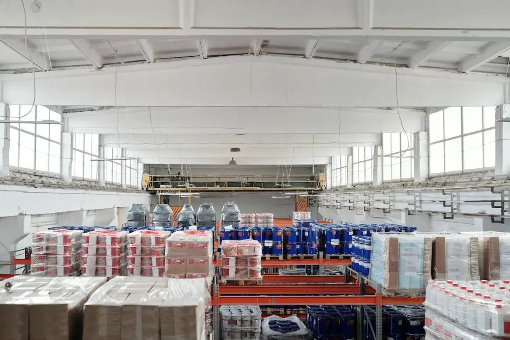
Typically floor loading in a commercial building
If the thickness of the slab is 150 mm (0.15 m) and assuming a unit weight of 25 kN/m3, the self-weight of the slab is;
self-weight of slab = 0.15 × 25 = 3.75 kN/m2
This load is applied as a uniformly distributed pressure load on the floor. In the same vein, the weight of finishes can be calculated by considering the unit weight of the finishes, the screeding, and the thickness.
For permanent equipment or heavy furniture on the floor of a building, it is sufficient to know the weight of the equipment and the way it is fixed to the floor for the sake of structural analysis and design. The way it is placed and fixed on the floor will determine if it is to be treated as a uniformly distributed load, concentrated load, or partially distributed load.
It may be important to assess whether dynamic analysis or vibration isolation may be needed for mechanical equipment. For some permanent medical equipment in hospitals, no such analysis may be required.
Partition loads on slabs are usually treated as line loads or converted to equivalent uniformly distributed loads. The weight of the partition and the nature of its fixity will determine if it can be converted to an equivalent UDL or modelled as a line load.
Live Load (variable actions)
Live loads on floors usually represent the occupancy loading on the floor, and are considered as the loads that are moveable on the floor of a building. This usually includes the weight of human beings and pets on the floor, furniture, household storage, office equipment, warehouse storage, the weight of vehicles on suspended garages, library books and shelves, etc.
As a result of this, the use of the building must be clearly defined so as to know the appropriate live loading to be used in the design. Live loads on floors are usually represented by uniformly distributed loads and concentrated loads. The uniformly distributed loads are commonly used for general design and global verifications, while the concentrated loads are used for local verifications and designs.
Typically floor loading in a store
For instance, the use of a uniformly distributed live load on a cantilever staircase may not give an onerous action effect when compared with using an equivalent concentrated live load. The values of live load on floors are published on the various codes of practice. For instance, the live load for residential buildings may be 1.5 kN/m2, while the live load for storage houses may get as high as 5 kN/m2.
By implication, a building designed for residential purposes should not be converted to a self-storage building without adequate assessment and strengthening.
Load Combination
To design a floor slab or deck, the dead loads and live loads on the floor are usually combined after an appropriate factor of safety is applied. The value of the partial factor of safety applied for each load combination depends on the limit state that is being assessed. A higher factor of safety is used for ultimate limit state verification, while a lower factor of safety is used for serviceability limit state verification.
In cohesionless soils, it is challenging to collect undisturbed samples, so we usually rely on the outcomes of in-situ testing (SPT or CPT tests) to determine the total settlement. Moreover, as the allowable soil pressure in these soils is determined more by considerations of settlement than bearing capacity failure, it is desirable to predict them accurately.
The average value of N to be used in the assessment of settlements and bearing capacity is determined by taking the SPT corrected values at foundation level N1, depth 1.5B (N2), and depth 2B (N3).
N = (3N1 + 2N2 + N3)/6 ——— (1)
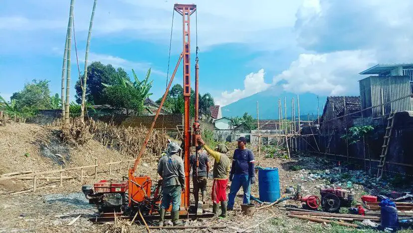
Figure 1: On-going SPT on site
The total settlement of a foundation can be divided into the following three components:
The immediate settlement ∆ which takes place due to elastic deformation of soil without change in water content.
The consolidation settlement ∆H which takes place in clayey soil mainly due to the expulsion of the pore water in the soil.
Secondary (creep) settlement ∆S which takes place over long periods due to the viscous resistance of soil under constant compression.
The immediate settlement is usually considered for footings on sand (cohesionless soils).
Correlation from Terzaghi and Peck
From Terzaghi and Peck’s (1967) correlation of settlement with SPT values, Teng (1969) proposed the following expression for the load for a given settlement of a footing of breadth B in a sand deposit with an SPT value of N:
For ∆ = 25 mm; p = 34.6(N – 3)[(B + 0.3)/2B]2 (in kN/m2) ——— (2)
for ∆ = 1 mm; p = 1.385(N – 3)[(B + 0.3)/2B]2 (in kN/m2) ——— (3)
Hence the settlement in mm for a load q in kN/m2 is as follows:
As it was found that Eq. (4) gives high values of settlements, Meyerhof proposed the following:
Actual settlement = settlement by Eq.(4)/1.5 ——— (5)
Meyerhof’s Formula Based on SPT Values for Cohesionless Soils
Meyerhof noted that Terzaghi and Peck’s correction overestimates the actual settlement considerably. He proposed the following formula based on SPT tests for settlement in mm for q in kN/m2 and B in meters;
∆ = 1.6q/N for B < 1.25 m ∆ = 2.84q/N × [B/(B + 0.3)]2 for B > 1.25 m ∆ = 2.84q/N for large rafts
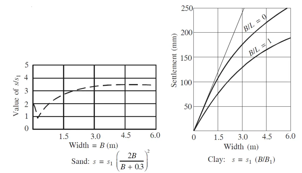
From test results, we know that in cohesionless soil, for the same intensity of load, the settlement of a footing increases with its width according to the following formula. (The settlement beyond B = 4 m can be taken as more or less constant.)
s = s1[2B/(B + 0.3)]2
where B is the breadth in meters and s1 is the settlement of a 0.3 m square plate.
Figure 2: Increase in settlements of footings with the width of footings in the sand and in clay (Varghese, 2012)
Another important empirical relation that Terzaghi established from his observation is that in both strip footing and also in pad footings of equal size and equally loaded the differential settlement that can be expected in all types of soil is about 50 percent of the maximum expected settlement of these footings.
In actual practice, the sizes of the footings can also be different. Hence in real-field situations, we may assume that the maximum expected differential settlement will be roughly 75% of the expected maximum settlement. Accordingly, if we assume an allowable differential settlement of 18 mm (3/4 inch) the maximum settlement we can allow in the footing will be 25 mm (1 inch).
In 1969, Teng proposed the following important relation between the settlement of a footing in sand and its SPT value N. [See Eq. (4)]
∆ = (0.722q/(N – 3)) × [(B + 0.3)/2B]2 (in mm)
where; s = settlement in mm q = intensity of load in kN/m2 B = breadth of footing in metres.
From the above, the net load required for 1 mm settlement will be as follows:
∆ = 1.385(N – 3)[(B + 0.3)/2B]2 (in kN/m2 per mm settlement)
where; q1 = bearing pressure for 1 mm settlement in kN/m2 N = corrected SPT value B = width of the footing in metres.
For 25 mm settlement, we get the following equation as the net allowable bearing pressure in kN/m2.
To this, we can add the effect of depth. Peck, Hanson and Thornburn (1974) used this relation to plot the graph for safe bearing capacity in sands for N values. The value of [(B + 0.3)/2B]2 decreases rapidly with B as shown in Fig. 3, so that the empirical value of qa for cohesionless soils with a variation of B can be expressed in kN/m2 as follows:
Figure 3: Variation of safe soil pressure with width based on shear failure and with soil pressure for 25 mm settlement (Varghese, 2012)
Therefore; qa = 10.5NB (for B < 1 m for 25 mm settlement) qa = 10.5N (for B > 1 m for 25 mm settlement) qa = 0.42N (kN/m2) (approx.) for 1 mm settlement for B > 1 m.
An average value of N for a depth B below the footing is taken as the N value for the calculation of bearing capacity.
References
Terzaghi, K. and Peck, R.B. (1967): Soil Mechanics in Engineering Practice, John Wiley & Sons, New York, 1967 Teng, W.C. (1969): Foundation Design, Prentice-Hall of India, New Delhi Peck, R.B., Hanson, W.E., and Thornburn, T.H., (1974): Foundation Engineering, John Wiley & Sons Varghese P.C. (2012): Foundation Engineering. PHI Learning Private Limited, New Delhi
When the beam-to-column connections in a frame are sufficiently rigid to maintain the original angles between intersecting members, the frame is considered a moment-resisting (rigid) frame. In essence, moment-resisting frames comprise the beams, columns, and the rigid connection between them.
The stiffness of the beams and columns are relied upon for resisting gravity and lateral loads and are essentially designed for such. Moment-resisting frames can be made of steel or reinforced concrete.
The rigid frame action is the development of shear forces and bending moments in the frame members and joints to resist lateral loads. By reducing positive moments in beam spans, the continuity at both ends of beams also helps moment-resisting frames in resisting gravity loads more effectively.
Figure 1: Typical construction of a moment-resisting frame building
The versatility of moment-resisting frames in architectural planning gives them certain advantages in building applications. They can be positioned at the building’s façade without having their depths restricted in any way. However, some restrictions on beam depths must be observed to allow for the passage of mechanical and air conditioning ducts.
They may also be positioned throughout the interior of the structure. They are regarded as having greater architectural versatility than other systems like braced frames or shear walls because there are no bracing elements to obstruct open spaces or openings.
Figure 2: Lateral displacement of the moment-resisting frames (Bungale, 2005)
In order to prevent storey drift under lateral loads, the depths of frame members are frequently governed by stiffness rather than strength. The lateral displacement of one level in relation to the level below is referred to as the story drift. It is a major concern in the serviceability assessment of buildings especially because of the effects of wind.
Commonly used drift limitations for wind-related building designs range from 1/400 to 1/500 of the story height. These restrictions are thought to be generally adequate to reduce damage to nonstructural walls and partitions, cladding, and other surfaces.
Then inherent flexibility of moment-resisting frames could lead to more drift-induced nonstructural damage than in other systems under seismic loads. It is important to keep in mind that seismic drift, which includes structures’ inelastic responses, is normally limited to 1/50 of the story height, which is around ten times bigger than the permitted wind drift. Particularly for frames intended to withstand seismic loads, the strength and ductility of the connections between beams and columns are very important factors to consider.
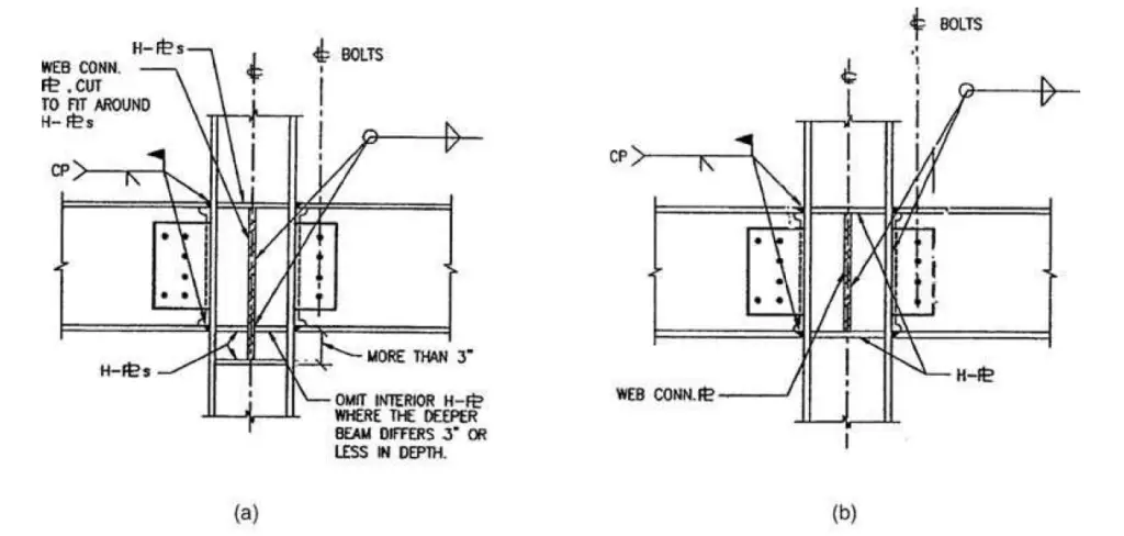
Consider the welded moment connection details from Figure 3, which were applied in North American seismic zones during the 25 years before the Northridge earthquake. A high-strength bolted shear tab connection and full-penetration field-welded top and bottom beam flanges were generally used for the connection. This kind of connection was thought to be capable of producing significant inelastic rotations.
Figure 3: Pre-Northridge moment connections: (a) unequal-depth beams to column flange connection; (b) equal-depth beams to column flange connection (Bungale, 2005)
The January 17, 1994, Northridge earthquake in California, with a Richter magnitude of 6.7, and the January 18, 1995 Kobe earthquake, with a Richter magnitude of 6.8, both damaged over 200 steel moment-resisting frame buildings and made engineers less confident in the use of the moment frame for seismic design.
Steel moment frames did not perform as well as planned in either of these earthquakes. The connections that failed almost always belonged to the category depicted in Figure 3. Most of the damage was caused by fractures in the bottom flange weld connecting the girder and column flanges. Additionally, top flange fractures happened often (Bungale, 2005).
New connection procedures have been created, and the majority of construction codes are being amended, in light of the brittle fracture that was seen at the intersections of the beam and column. Designing beams so that the plastic hinges form away from the column face is the typical approach to some new design concepts.
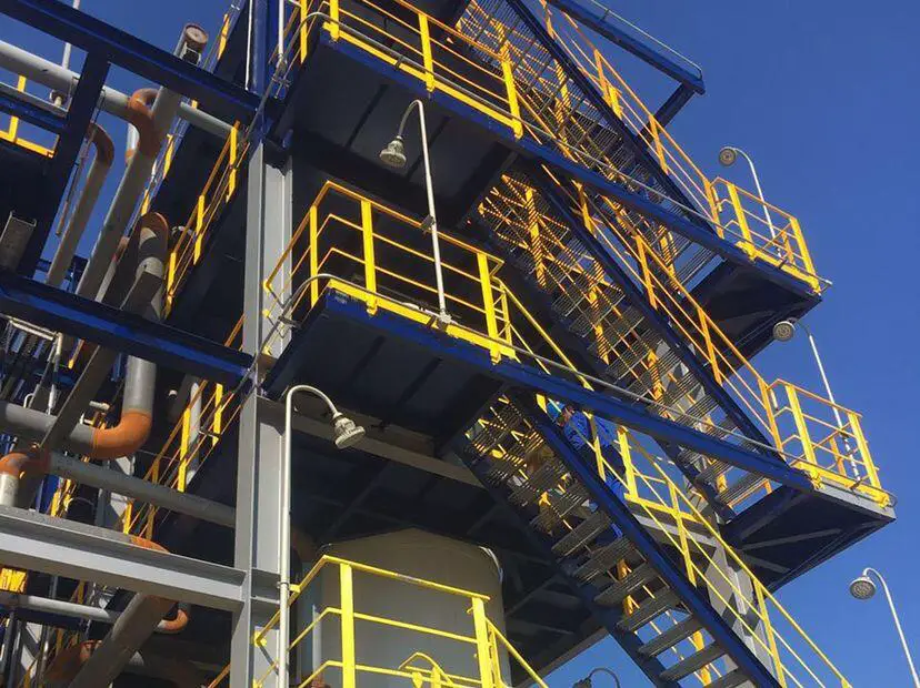
Figure 4: Moment-resisting frame in an industrial building
Deflection Behaviour of Moment-Resisting Frames
A moment-resisting frame cannot displace laterally without bending the beams and columns because of the rigid connections between the beams and columns. Therefore, the bending rigidity of the frame elements serves as the main source of lateral stiffness for the entire structure.
It is beneficial to consider the deflections of a rigid frame as composed of two components (comparable to the deflection components of a structural element like a vertical cantilever column) to comprehend its lateral deflection characteristics.
The cantilever column’s primary deflection is caused by bending, and its secondary component is caused by shear. The shear component might not be taken into account when calculating deflection unless the column is reasonably short. However, both of these elements carry equal importance in moment-resisting frames. Cantilever bending and frame racking are common names for the bending and shear deflection parts of rigid frames.
Cantilever Bending Component
A moment-resisting frame behaves like a vertical cantilever when resisting overturning moments, which causes axial deformation of the columns. The columns on the windward face lengthen while those on the leeward face shorten. The building rotates about a horizontal axis due to this alteration in column lengths. The resulting lateral deflection, as depicted in Figure 5, is comparable to the cantilever’s bending deflection component.
Figure 5: Rigid frame deflections: Forces and deformations caused by external overturning moment (Bungale, 2005)
Shear Racking Component
This rigid frame response, depicted in Figure 6, is comparable to the cantilever column’s shear deflection component. Due to the rigid connections between the beams and columns, bending moments and shears develop in the beams and columns as the frame moves laterally. The horizontal shear above a given level due to lateral loads is resisted by shear in each of the columns of that story (Figure 6).
Figure 6: Rigid frame deflections: forces and deformations caused by external shear (Bungale, 2005)
The storey columns then begin to bend in a double curvature with points of contraflexure at roughly midstory levels as a result of this shear. Equilibrium is achieved when the sum of the moments of the columns above and below a joint equals the sum of the moments of the beams on each side of the column.
The beams also bend in a two-fold curvature to resist the bending, with points of contraflexure roughly in the middle of the span. The overall shear racking of the frame is caused by the accumulated bending of the columns and beams. According to Fig. 3.4b, the deflected shape caused by this component has a shear deflection structure.
About 70% of a moment frame’s overall sway results from the shear mode of deformation, with the remaining 30% coming from column bending and the other 10% to 15% from beam flexure. This is due to the fact that in a rigid frame, the column stiffness, as determined by the Ic/Lc ratio, is often significantly higher than the beam stiffness ratio, Ib/Lb, where;
Ib = moment of inertia of the beam Ic = moment of inertia of column Lb = length of the beam Lc = length of the column
Therefore, to reduce lateral deflection, one should consider starting with increasing the stiffness of the beams. However, it is advisable to investigate the relative beam and column stiffnesses before making adjustments to the member stiffnesses in nontypical frames, such as for those in framed tubes with column spacing that is close to floor-to-floor height (Bungale, 2005).
The story drift increases with height due to the cumulative effect of building rotation, but that caused by shear racking tends to remain constant with height. In the highest stories, cantilever bending contributes more to story drift than shear racking does. Except in very tall and slender rigid frames, the bending impact typically does not exceed 10 to 20% of that caused by shear racking.
As a result, a medium-rise frame’s overall deflected shape typically has a shear deflection arrangement (Bungale, 2005). Therefore, it is possible to consider the total lateral deflection of a rigid frame as a combination of the following elements:
• Cantilever deflection due to axial deformation of columns (15 to 20%). • Frame shear racking due to bending of beams (50 to 60%). • Frame racking due to bending of columns (15 to 20%).
The panel zone of a beam-column connection, which is defined as the rectangular segment of the column web within the column flanges and beam continuity plates, along with the previously mentioned variables, also contributes to the overall lateral deflection of the frame. However, its impact rarely goes above 5% of the total deflection.
References
Bungale S. T. (2005): Wind and earthquake resistant buildings structural analysis and design. Marcel Dekker, New York
Load balancing is the most typical approach used in post-tensioned slab design for determining the amount and distribution of prestress after the selection of the initial slab thickness. During the load balancing, a portion of the load is balanced out by the transverse loads that the draped tendons in each direction impose on a slab.
Under the balanced load, the slab remains flat (without curvature) and is only susceptible to the ensuing longitudinal compressive P/A stresses. When assessing service load behaviour, particularly when predicting load-dependent deflections and figuring out how much cracking has occurred and how much crack control has been applied, consideration is given to the remaining imbalanced load.
Figure 1: Interior edge-supported slab panel (Gilbert et al, 2017)
Consider the interior panel of the two-way edge-supported slab shown in Figure 1. The panel has parabolic tendons in both the x and y axes and is supported by walls or beams on all sides. The upward forces per unit area that the tendons in each direction exert if the cables are uniformly spaced in each direction are;
wpx = 8Pxzd.x/lx2 ——— (1)
and
wpy = 8Pyzd.y/ly2 ——— (2)
where Px and Py are the prestressing forces in each direction per unit width, and zd.x and zd.y are the cable drapes in each direction.
The uniformly distributed downward load to be balanced per unit area wbal is calculated as:
wbal = wpx + wpy ——— (3)
In practice, perfect load balancing is not possible, since external loads are rarely perfectly uniformly distributed. However, for practical purposes, adequate load balancing can be achieved (Gilbert et al, 2017). Any combination of wpx and wpy that satisfies Equation (3) can be used to make up the balanced load. The smallest quantity of prestressing steel will result if all the loads are balanced by cables in the short-span direction, i.e. wbal = wpy.
Figure 2: Post-tensioned slab construction
However, under unbalanced loads, serviceability problems in the form of unsightly cracking may result. It is often preferable to distribute the prestress in much the same way as the load is distributed to the supports in an elastic slab, i.e. more prestress in the short-span direction than in the long-span direction. The balanced load resisted by tendons in the short direction may be estimated by:
wpy = [lx4/(δly4 + lx4)] × wbal ——— (4)
where δ depends on the support conditions and is given by:
δ = 1.0 for 4 edges continuous or discontinuous = 1.0 for 2 adjacent edges discontinuous = 2.0 for 1 long-edge discontinuous = 0.5 for 1 short edge discontinuous = 2.5 for 2 long + 1 short edge discontinuous = 0.4 for 2 short + 1 long edge discontinuous = 5.0 for 2 long edges discontinuous = 0.2 for 2 short edges discontinuous
Equation (4) is the expression obtained for that portion of any external load which is carried in the short-span direction if twisting moments are ignored and if the mid-span deflections of the two orthogonal unit-wide strips through the slab centre are equated.
With wpx and wpy selected, the prestressing force per unit width in each direction is calculated using Equations (1) and (2) as:
Px = wpxlx2/8zd.x ——– (5)
and
Py = wpyly2/8zd.y ——– (6)
Equilibrium dictates that the downward forces per unit length exerted over each edge support by the reversal of cable curvature (as shown in Figure 1) are:
wpxlx (kN/m) carried by the short-span supporting beams or walls wpyly (kN/m) carried by the long-span supporting beams or walls
The total force imposed by the slab tendons that must be carried by the edge beams is, therefore:
wpxlxly + wpylylx = wballxly ——– (7)
and this is equal to the total upward force exerted by the slab cables.
Therefore, for this two-way slab system, to carry the balanced load to the supporting columns, resistance must be provided for twice the total load to be balanced (i.e. the slab tendons must resist wballxly and the supporting beams must resist wballxly). This requirement is true for all two-way floor systems, irrespective of construction type or material.
At the balanced load condition, when the transverse forces imposed by the cables exactly balance the applied external loads, the slab is subjected only to the compressive stresses imposed by the longitudinal prestress in each direction, i.e. σx = Px/h and σy = Py/h, where h is the slab thickness.
Article Source: Gilbert R. I, Mickleborough N. C., and Ranzi G. (2017): Design of Prestressed Concrete to Eurocode 2 (Second Edition). CRC Press, Taylor and Francis Group.
The internal resistance that the soil mass can provide per unit area to withstand failure and sliding along any plane within it is known as the shear strength of soil. Shear strength can be measured in a lab, out in the field, or perhaps both.
Triaxial compression tests, unconfined compression testing, and direct shear box tests are just a few of the tests that may be used in the lab. In situ tests are typically performed for both design purposes and to evaluate the reliability of laboratory experiments. Field vane, standard penetration test (SPT), and cone penetration test (CPT) are some of the available in-situ testing (CPT).
For a variety of issues, including the design of foundations, slope stability, retaining walls, and dam embankments in civil engineering applications, the shear strength of soil is necessary. An engineer’s responsibility to ensure that the structure is secure against shear failure in the soil that supports it and does not experience excessive settlement is very critical.
It is very important to understand the soil’s behaviour under stress and strain as well as its deformation and shear strength. When dealing with clay soil, which is renowned for being highly malleable and having poor shear strength, these concerns become more problematic and difficult.
Engineers have generally spent a lot of time measuring the shear strength of soils, but not as much time figuring out the fundamental elements that affect shear strength. The goal of this article is to learn more about the shear strength of soils and how the fundamental variables affect the shear strength of clay soils. The present analysis has focused primarily on the sources of shear strength in cohesive soils since these causes are less well understood than the causes of strength in cohesionless soils.
Components of shear strength in soils
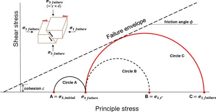
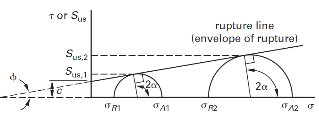
The angle of internal friction (ϕ) and cohesion (c) are the two important parameters that determine the shear strength of soils. The soil’s maximum capacity to withstand shear stress under a given load is determined by the two factors. The cohesion measures the ionic attraction and chemical cementation between soil particles, and the angle of internal friction shows the amount of friction and interlocking that exists among soil particles.
By carrying out the necessary shear strength tests, it is possible to determine both of these characteristics in a laboratory. In-situ soil shear strength parameters can only be estimated using a limited number of field test procedures. While forces of attraction between clay-sized particle particles affect the strength of cohesive soils, friction between the particles is the primary driver of strength in coarse soils. Due to their ability to give soils flexibility and cohesion, it is convenient to think of such particles as plastic particles.
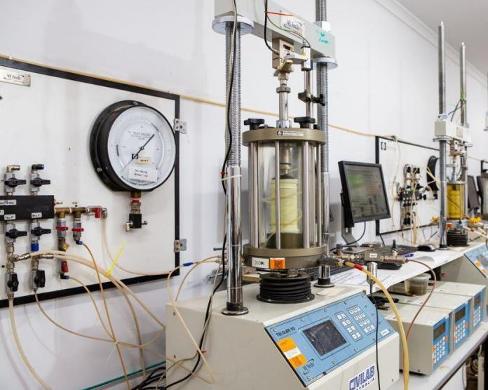
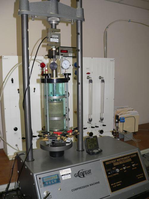
Triaxial testing machine
Using the cohesion and angle of internal friction, the shear strength of a soil mass can be calculated using the Mohr-Coulomb shear strength equation as follows;
τ = σ tan(ϕ) + c ——— (1)
Mohr’s circle plot for shear strength of soils
The angle of internal friction
The friction angle for a particular soil is the angle on the graph (Mohr’s Circle) where shear failure takes place. Soil friction angle is typically indicated by the symbol “ϕ“. Internal friction is typically understood as the grading-based resistance that two planes experience when they move in opposition to one another.
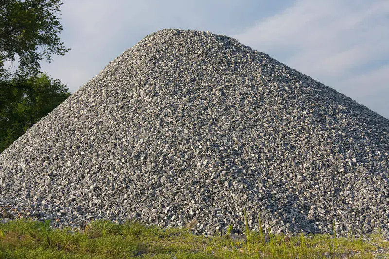
If the soil specimen is given time to solidify, friction increases as the typical load increases. Sand-containing gravels usually have a friction angle of 34° to 48°, loose to dense sand has a friction angle of 30° to 45°, silts have a friction angle of 26° to 35°, and clay has a friction angle of about 20°.
All well-graded soils have a high angle of internal friction values. Particle size, compaction force, and applied stress level are factors that affect friction angle. Although certain research has made it clearer by stating that the friction angle increases as the maximum particle size increases, friction angle does increase with an increase in particle size. With an increase in surface angularity and roughness, friction angle has also been observed to increase.
Cohesion
It is possible to define cohesion as the specific portion of shear strength that results from the forces of attraction that exist between the clay minerals. The ability of soil to act like glue, binding the grains together, is known as cohesion. It is an important element of shear strength, especially for fine-grained soils. The letter “c” is commonly used to indicate soil cohesion. Silt typically has a cohesion value of 75 KPa, but the cohesion of clay can range from 10 to 400 KPa, depending on how stiff the clay is (from soft to high).
An extremely strong cohesion can be produced by naturally occurring minerals that have leached into the soil, such as caliches and salts. The soil grains will tend to fuse together due to heat fusion and sustained overburden pressure, resulting in substantial cohesion.
At the start of the stress condition, cohesion mobilizes and achieves its peak levels around the plastic limit, or at the start of structural collapse. Cohesion increases as one approach the shrinkage limit and diminishes as one approaches the liquid limit. With the exception of clayey soils, where a rise in stress induces an increase in molecular bonds, cohesion often does not increase as stress increases.
Factors affecting theshear strength of soils
Many factors are recognized to have a direct effect on the shear strength of cohesive soils and play a significant role in strength determination. These factors include;
clay content
clay mineralogy
plasticity index
water content
dry density, and
strain rate
A brief review of these factors, as reported by previous investigators is outlined below.
Clay Content
The cohesion and the friction angle are significantly affected by the percentage of clay in the soil mass. The addition of more clay increases the cohesiveness for water contents that are a little above the optimum water content. If the moisture level is considerably higher than the optimum water content, this improvement could not be possible. Increased clay fractions will result in stronger binding forces, which will increase the soil’s strength.
Clay mineralogy and microfabric
The shear strength of cohesive soils is influenced by the environmental conditions as well as the mineral composition of the clay. Clay’s shear strength is decreased by the presence of clay minerals. The weakest and most prone to swelling of the clay minerals is the expansive clay montmorillonite.
In expansive soils, shrinkage and swelling have completely different impacts on the shear strength. Fully inflated clay typically has poor shear strength, whereas dry shrinking clay might have better cohesiveness. The principal stresses of the soil’s shear strength are greatly influenced by the clay minerals.
Typical clay minerals
The amount of kaolinite in the soils is directly related to the primary stress that was measured (σ1). This might be explained by the characteristics of kaolinite particles, which among the clay mineral species under investigation have the biggest grain sizes. The microfabric, or diameter-to-thickness ratio, of the kaolinite particles, is the smallest. As a result, the edge surface of the kaolinite particles is quite large.
The charge is differently distributed in kaolinite, with one basal plane being highly charged and the other uncharged. High major stress resulted from this for both the calcium and sodium types. Intergranular friction is the main cause of kaolinite’s relatively high major stress.
Plasticity Index
The behaviour of cohesive soil is significantly influenced by the plasticity of the soil. Numerous academics are working to understand how plasticity affects the shear strength of cohesive soils. Shear strength decreases as the plasticity index rises. According to research, high plastic clay has stronger binding pressures, which increases the soil’s shear strength. It was found that clay soils with higher calcium carbonate contents have lower plasticity indices and significantly higher shear strengths.
Skempton looked at how plasticity index affected shear strength and proposed a formula that is frequently used to forecast shear strength. Skempton discovered that the plasticity index PI (%) for the vane shear test is a linear function of the undrained shear-strength ratio of properly consolidated clays, as shown in Equation below (1).
Water content
Cohesion typically increases with water content up to the optimum water content, after which it generally decreases with water content. On the other hand, friction reduces as water content rises and eventually stabilizes at a value close to its maximum. As a result, shear strength decreases as water content rises because suction’s contribution to shear strength declines.
According to Lambe and Whitman, the undrained shear strength is independent of a change in total stress unless a change in water content occurs and postulated that the water content is a function of the maximum principle consideration stress alone. Similar studies discovered that a nonlinear function could be used to depict the link between the amount of water present in soils and the undrained shear strength.
In compacted clay soil, the shear strength falls as the water content rises. The shear strength of soil varies exponentially across consistency limits, and the corresponding fitting equation aids in calculating strength at any relevant water content.
With a drop in water content, it is anticipated that the shear strength will rise. This presumption is in line with some observations that clay soils compacted with a moisture content lower than the ideal behave in a coarser manner as a result of aggregation than would be allowed by the grading. Because clay particles aggregate into aggregates with larger effective particle sizes, a fall in water content in clay soils causes a higher friction angle.
Dry Density
The dry density of cohesive soil has a significant impact on its shear strength. Because shear strength increases as dry density increases, a rise in density or a fall in the void ratio will result in an increase in friction angle. With an increase in the soils’ dry density, the primary stress (σ1) increases.
Strain Rate
The testing preparations with relation to drainage conditions and the type of soil tested determine how significantly the shearing rate affects the results. In clays, the strain rate is typically quite low to allow the pore water pressure to dissipate. One test could take several days to complete. However, a more accurate approximation for an undrained specimen can be found in the drained strength measured in a test at a rate of 1.2 to 1.3 mm/min.
With an increase in shear strain rate, undrained shear strength rises. It should be noted, though, that the undrained strength would be underestimated by the quick direct shear testing.
Post-tensioning is a type of prestressing that involves tensioning the tendons after the concrete has hardened, and predominantly transferring the prestressing force to the concrete through the end anchorages. The strength of concrete members is commonly enhanced by post-tensioning, which is a prestressing technique commonly used by engineers.
In post-tensioned concrete, compressive stresses are introduced into the concrete in prestressed members to lower tensile stresses induced by applied loads, such as the member’s own weight (dead load). Compressive stresses are applied to the concrete by means of prestressing steel, such as strands, bars, or wires.
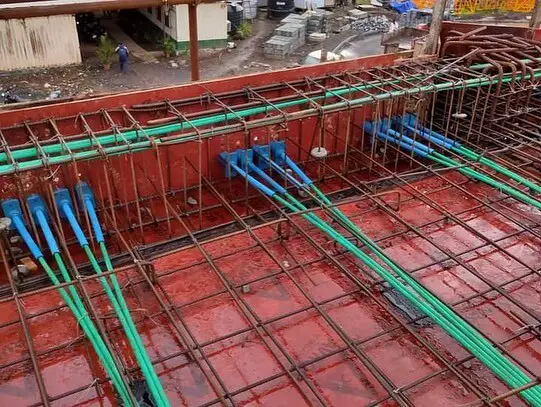
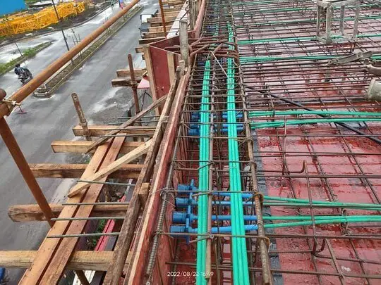
Figure 1: Typical post-tensioned slab arrangement
Construction of post-tensioned concrete members
In post-tensioned concrete, the concrete is cast around hollow ducts that are fitted to any desired profile after the formwork is in place. Normally, the steel tendons are in the ducts during the concrete pour, unstressed in them. However, they can also be threaded through the ducts at a later point in time. Tendons are tightened after the concrete reaches the desired strength. Tendons can either be stressed from both ends, or from one end while the other is anchored.
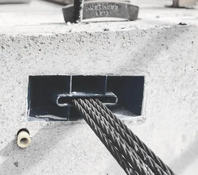
At each stressed end of the concrete element, the tendons are then anchored. After the tendons are anchored, the prestress is maintained by bearing the end anchorage plates onto the concrete, which compresses the concrete during the stressing operation. Every time the cable’s direction changes, the post-tensioned tendons impose a transverse force on the member.
Figure 2: Multi-strand tendon system and anchorage block
The tendons’ ducts are frequently filled with grout under pressure once they have been anchored and confirmed that no further stressing is needed. In this way, the tendons are bonded to the concrete and are more efficient in controlling cracks and providing ultimate strength. If a tendon is later lost or damaged, bonded tendons are also less prone to corrode or cause safety issues.
However, there are instances where tendons are not grouted for economic reasons and remain permanently unbonded. The tendons are grease-coated and enclosed in a plastic sleeve in this method of construction.
Unbonded post-tensioned slabs are frequently utilized in North America and Europe, despite the fact that they provide only around 75% of the ultimate strength of a beam or slab that is provided by bonded tendons. Post-tensioning is the most common in in-situ prestressed concrete. Relatively light and portable hydraulic jacks make on-site post-tensioning an attractive option.
Applications of post-tensioning
Prestress is typically applied on-site to a variety of structures using post-tensioning of concrete. Members such as slabs and beams are easily post-tensioned on site. Large-span bridge girders are segmentally built using post-tensioning as well.
When a structure is post-tensioned, there is a great deal of flexibility in how the prestress is delivered since the tendon profiles may be easily changed to match the applied loading and the support circumstances. Stage stressing, which involves applying incremental prestress as needed at various building stages as the external stresses progressively rise, is also well suited to post-tensioning.
Components of post-tensioned systems
The components of post-tensioned systems are prestressing strands, anchorages, corrugated galvanized steel or plastic ducts (including grout vents for bonded tendons), and grout. The ducts are fixed to temporary supports (typically attached to the non-prestressed reinforcement of a beam) at strategic intervals throughout the formwork to create the post-tensioned tendon profile.
The strands are typically supported on bar seats for slabs on the ground. As shown in Figure 3, respectively, the ducts that contain the prestressing tendons may be made of plastic ducting or corrugated steel sheathing in more modern innovations.
Figure 3: Prestressing tendons are made of plastic ducting
In a typical continuous floor slab, a post-tensioning strand is laid out schematically in Figure 4. A continuous beam would likewise be covered by the details. The design loads, as well as the placement and kind of supports, determine the prestressing tendon’s profile. The concrete is given time to cure after casting until it reaches the necessary transfer strength.
Figure 4: Tendon layout and details in a continuous post-tensioned slab.
Depending on the system being used or the requirements of the structural design, an initial prestressing force may be applied when the concrete compressive strength reaches about 10 MPa (to facilitate the removal of forms), and the strands will then be re-stressed up to the initial jacking force when the concrete has reached the required strength at transfer.
The grouting of the ducts following the post-tensioning procedure is a common practice in many regions of the world. At one end of the duct, grout is injected into it under pressure. To make sure that the wet grout completely fills the duct during the grouting operation, grout vents are placed at various points along the duct (as illustrated in Figure 4).
The post-tensioned tendon is essentially bound to the surrounding concrete once the grout has dried and set. The grout has various benefits, including enhanced tendon corrosion protection, increased prestressing steel utilization in bending under ultimate limit state conditions, and—most importantly—prevention of tendon failure owing to localized damage at the anchorage or an unintentional strand cutting.
A hydraulic jack working on the concrete at the stressing anchorage at the member’s one end (commonly referred to as the live end) is used to apply the prestress (Figure 5). Figure 5 shows a hydraulic jack stretching the multi-strands in a duct.
Figure 5: Typical hydraulic jack
An anchor head, accompanying wedges needed to secure the strands, and an anchorage casting or bearing plate make up the live end of a post-tensioning anchorage system (see Figure 2). Although these anchorages exist in a variety of sizes and shapes, their load transmission mechanism generally stays the same. The hydraulic jack pulls the strands sticking out behind the anchorage during the stressing process until the necessary jacking force is attained. Figures 3.6d and e depict typical live-end anchorages for a flat ducted tendon.
Figures 5 and 36 depict the wedges used to clamp the prestressed strands at the live end of a slab tendon prior to post-tensioning. The strands are typically painted prior to post-tensioning to make it easier to evaluate each strand’s elongation following the stressing procedure. The wedges in the anchor head secure the post-tensioned strands after jacking, and the anchor casting or bearing plate transfers the load from the jack to the structure.
Figure 6: Live end anchorage
When just one end of the member needs to be stressed, the non-stressing end is frequently in the form of an internal dead-end anchoring, where the ends of the strands are cast in the concrete (see Figure 7). This is true even if the live anchorage can also be utilized at an exterior non-stressing end.
Despite the fact that there are numerous variations on this anchorage, the basic idea is to use either swaged barrels bearing on a steel plate or extending out the exposed strand bundle to generate local anchor nodules or bulbs at the extremities beyond the duct.
Figure 7: Dead-end anchorage
To stop concrete from entering the duct during construction, it is sealed. Only after the surrounding concrete has acquired the necessary transfer strength is the tendon stressed. Figure 5 illustrates common anchorage systems for use with multi-strand setups. Following the completion of the stressing, the strands are cut off. Tendons within a member can be connected using tendon couplers and intermediate anchorages.
Grouting of the tendons
The durability of the structure depends on a well-designed grout mix and well-grouted tendons. The positioning of the grout vents, which are used to inject grout and release air from the duct at grout outlets, is one of many elements that determine whether a grouting operation is successful.
As the grout is injected into the duct at the tendon end or anchorage point, vents are needed at the high points of the tendon profile to release the air. Air and water can be evacuated from the crest of the duct profile using vents at or close to the high points. The vent at the far end of the duct emits grout, indicating that the duct is entirely filled with grout.
Figure 8: Typical post-tensioned slab
The installation of either temporary or permanent grout caps guarantees that the anchorages are completely filled and enable later grouting verification. Grout vents are frequently seen at the duct’s high points over the internal supports and at the end anchorages (as illustrated in Figure 4). The ducts into which the grout is injected must be big enough to allow for simple strand installation and unhindered grout flow during the grouting process.
Before grouting the duct, an air pressure test is typically conducted to ensure that the risk of grout leaking is reduced. Grouting has a set process and requires skilled labourers to be effective. The grout is continuously and continuously injected into the duct intake.
The vent is not shut off when the grout emerges from it until the emerging grout has the same viscosity and consistency as the grout being pumped into the intake. After confirming that the grout has the necessary consistency and viscosity, intermediate vents along the tendon are closed sequentially.
Prestressed concrete is a special type of reinforced concrete. Concrete is weak in tension, and tends to crack when subjected to tensile stresses. Prestressing entails applying an initial compressive load to the structure, in order to reduce or eliminate the internal tensile stresses and, consequently, control or eliminate cracking. By acting on the concrete, highly tensioned steel reinforcement (tendons) apply and maintain the initial compressive load.
A prestressed concrete section is significantly stiffer than an equivalent (often cracked) reinforced concrete section because cracking is minimized or eliminated. Additionally, prestressing may impose internal forces that have the opposite sign from the external loads, which may greatly reduce or even completely eliminate deflection.
The development of prestressing technologies utilized in the production of prestressed concrete has evolved throughout time, mostly as a result of research and development by specialized firms involved in the planning and construction of prestressed concrete structures. These companies regularly operate on related projects including lifting huge structures, cable-stayed bridges, suspension bridges, and soil and rock anchors that call for specialized knowledge and unique equipment, materials, and designs. Each company’s website or direct contact with that company will typically provide information on its items.
The fundamental types of prestressing and the prestressing components are discussed in this article with examples. These include the wire, strand, and bar steel tendons, that are utilized to prestress the concrete.
Types of Prestressing Steel
High-strength steel is typically utilized as tendons in prestressed concrete construction and comes in three basic types which are;
Cold-drawn stress-relieved round wire;
Stress-relieved strand; and
High-strength alloy steel bars.
Figure 1: Types of strand. (a) 7-wire strand. (b) 19-wire strand – alternative crosssections. (c) Cable consisting of seven 19-wire strands.
Cold-drawn stress-relieved round wire
Generally speaking, a wire, strand, or bar (or any distinct set of wires, strands, or bars) that is meant to be pre- or post-tensioned is referred to as a tendon. Wires are round, cold-drawn, solid steel parts having a diameter typically between 2.5 and 12.5 mm. Hot-rolled medium to high-carbon steel rods are pulled through dies to create wires of the desired diameter to create cold-drawn wires. Steel is cold-worked throughout the drawing process, changing its mechanical characteristics and improving its strength.
The wires are then continuously heated and straightened to relieve stress, increase ductility, and create the desired material qualities (such as low-relaxation). For wires, the normal characteristic tensile strength fpk ranges from 1570 to 1860 MPa. To enhance the bonding properties of wires, these techniques may be used.
Although wire diameters differ from country to country, they are typically between 4 and 8 mm. In prestressed concrete construction, the use of wires has decreased recently, with 7-wire strand being favoured in most situations.
Figure 2: Cables in post-tensioning
Stress-relieved strand
The most popular kind of prestressing steel is stress-relieved strand. There are options for both 7-wire and 19-wire strands. According to Figure 1a, a seven-wire strand is made up of six tightly coiled wires that are centred around a central core wire with a seventh, somewhat larger diameter wire.
The six spirally wound wires have a pitch that ranges from 12 to 18 times the normal strand diameter. The seven-wire strands’ nominal diameters range from 7 to 15.2 mm, and their typical characteristic tensile strengths fall between 1760 and 2060 MPa.
Pretensioned and post-tensioned applications both frequently use seven-wire strands. Two layers of 9 wires, or alternately two layers of 6 and 12 wires, are spirally coiled around a core wire to make a 19-wire strand. The spirally wound wires have a pitch that is 12–22 times the nominal strand diameter.
The usual cross-sections are depicted in Figure 1b, and the nominal diameters of 19-wire strands in common usage range from 17 to 22 mm. While 19-wire strand is used in post-tensioned applications, pretensioned applications, where the transfer of prestress depends on the surface area of the strand available for binding to the concrete, are not advised due to 19-wire strand’s comparatively low surface area to volume ratio.
By drawing the strand through a compacting die, the diameter of the strand can be reduced while keeping the steel’s cross-sectional area constant. Strand compression also makes it easier to grasp the strand at its anchorage. The strand’s mechanical characteristics differ slightly from those of the wire from which it is produced. This is due to the fact that when under tension, stranded wires have a tendency to somewhat straighten, which lowers the apparent elastic modulus. For design reasons, the elastic modulus is Ep = 195 × 103 MPa, and the yield stress of the stress-relieved strand is approximately 0.86fpk.
As seen in Figure 1c, cables are made up of a collection of strands that are frequently braided together from multiple wires. Typically, stay cables are produced straight from strands and are utilized extensively in cable-stayed and suspension bridges.
High-strength alloy steel bars
Hot-rolled high-strength alloy steel bars have alloying components added during the steelmaking process. To strengthen the relationship, some bars have ribs. Bars are single, straight lengths of solid steel that are larger in diameter than wire. They normally have diameters between 20 and 50 mm and typically have a minimum breaking stresses between 1030 and 1230 MPa.
In terms of structural performance and constructability, concrete-filled steel tubular (CFST) members provide a number of advantages over bare steel or reinforced concrete elements. These advantages have led to a wider range of practical applications, such as increased strength and ductility of the core concrete due to the steel tube’s confining effect, increased resistance to local buckling of the steel tube due to the core concrete’s restriction of inward deformations, improved fire resistance of CFST members due to the concrete’s heat sink effect, and improved constructability due to the steel tube acting as formwork during the concrete pouring.
Torsion occurs in structural members as a result of twisting due to an applied torque. CFST beams with curved on-plan surfaces, CFST corner columns of structures that twist under wind or earthquake loads, and I-beams with CFST compression flanges that experience lateral torsional buckling are common instances where such actions might occur in CFST members.
Furthermore, because the stiffness centre and the mass centre of these structures do not lie in the same location, in reality, the piers of curved bridges, skew bridges, and complicated building structures are always exposed to torsion under horizontal earthquake action.
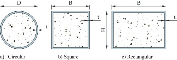
It is well known that the shape of the cross-section affects the confinement effect in CFST members and that square CFST columns typically possess somewhat lower strength and ductility than similar circular CFST columns. Square CFST columns, however, are frequently used for practical reasons, such as more elaborate beam-to-column connections.
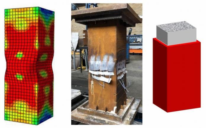
Concrete-filled steel tube columns (Zhang et al, 2022)
Numerous researchers have conducted experimental and numerical studies on the behaviour of square CFST members under various loading conditions. These include a number of tests on square CFST beam-columns that were loaded under pure compression to bending. Additionally, experimental tests have been conducted on square CFST beam-columns utilizing high-strength steel sections with yield strengths up to 750 MPa, along with computational calculations. Interaction formulae for design purposes have been developed on the basis of the findings.
A paper on the torsional rigidity of CFST square columns was recently published in the journal Structures (Elsevier) by researchers from the Department of Civil and Environmental Engineering at Imperial College London in London, the School of Civil and Architecture Engineering at Northeast Petroleum University in Daqing, China, and the School of Civil Engineering & Architecture at Nanjing Institute of Technology in Nanjing, China.
According to the authors, available literature makes it obvious that while there have been several examinations into the structural response of square CFST sections in compression and bending, there has been less research into the torsional performance of square CFST sections.
To address the knowledge gap, the authors used the concept of minimum strain energy to develop an analytical equation for the uniform torsional rigidity of square CFST sections. Since it is generally known that uniform torsional stiffness prevails over non-uniform (warping) torsional rigidity in the case of closed sections, emphasis is made on the uniform torsional rigidity of square CFST sections.
The accuracy of the obtained formula was then evaluated using current theoretical findings, test data, and the finite element simulations carried out in the study. Finally, the significance of the theoretical formulation’s constituent parts is examined, and a simplified design formula was provided.
Torsional deformation of square CFST cross-section (Zhang et al, 2022)
Basic Assumptions in the Determination of Torsional Rigidity
When determining the torsional rigidity of square CFST sections, the following fundamental presumptions are made:
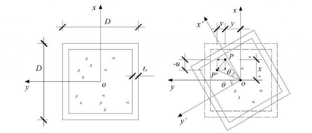
(1) Every point in the cross-section rotates via the angle θ(z) about the centre of twist because the square CFST members’ cross-sections do not deform in-plane when they are twisted. The stiff peripheral assumption of thin-walled bars made by Vlasov is analogous to this one. This assumption allows for the determination of the transverse deformations at any location on the cross-section of square CFST members.
(2) During uniform torsion of the square CFST members, there is no longitudinal slip at the interface between the core concrete and the steel tube, i.e., the longitudinal warping of the steel and concrete are compatible at the interface.
(3) Pure torque is applied to the square CFST component, which results in no restrictions on any variations in the longitudinal warping and does not vary along the length of the member.
The notations used in the study are as follows: Es, Gs, and μs are the steel cross-modulus sections of elasticity, shear modulus, and Poisson’s ratio, whereas Ec, Gc, and μc are the filled concrete’s modulus of elasticity, shear modulus, and Poisson’s ratio. The section depth and wall thickness of the steel tube are designated by D and t, respectively, while the length of the square CFST member is denoted by L.
Torsional deformation occurs when a member is subjected to a torsional moment (T), where θ(z) is the angle at which the cross-section is twisted. For a member of length L, the angle of twist at the tip, or tip rotation, is given by:
θL = TL/(GJ)k ——— (1)
where (GJ)k is the torsional rigidity of CFST cross-sections, considering the contributions of both the concrete core and the steel tube, to be determined in this study.
Theoretical Formulations
In the study, the strain energy of the concrete core and the steel tube was determined as;
U = ½(GJ)k,SEϕ2L ——– (2)
where (GJ)k,SE is the uniform torsional rigidity derived from the principle of minimum strain energy of a square CFST cross-section, which can be expressed as follows:
(GJ)k,SE = 0.1407D4GcΨ(m, α) ——– (3)
Where; Ψ is the non-dimensional constant of uniform torsional rigidity of square CFST sections, m = Gs/Gc is the ratio of the shear modulus of steel to that of concrete, α = As/Ac, referred to as the steel ratio, is the ratio of the cross-sectional area of the steel As to the cross-sectional area of the concrete Ac, and can be approximated as α ≈ 4t/D.
When the steel ratio α = 0, the equation (3) reduces to the uniform torsional rigidity of a square section of a single material (pure concrete), i.e.
(GJ)k,SE ≈ 0.1407D4Gc ——– (4)
The exact solution, as given by Timoshenko and Goodier (1970), is:
(GJ)k,TG = 0.1406D4Gc ——– (5)
It can be seen that the difference between the analytical solution and the exact solution is only 0.1%. This shows that the longitudinal displacement mode assumed in the paper is reasonable, and that the principle of minimum strain energy has been suitably applied.
Experimentation Verification
The outcomes of a torsion test performed by prior researchers on a square CFST member were taken into consideration in order to further confirm the accuracy of the derived uniform torsional rigidity. The tested member’s geometrical and material characteristics are shown in the Table below where fy is the steel’s yield strength, fcu and fck are concrete’s cube and cylinder strengths.
Property
Chen (2003)
Kitada and Nakai (1991)
Length L (mm)
1620
1590
Depth D (mm)
200
123.5
Thickness t (mm)
4.5
4.5
fy (MPa)
261.4
274
fcu (MPa)
39.0
25.6
fck (MPa)
26.1
17.2
Es (GPa)
206
206
Ec (GPa)
32.4
28.1
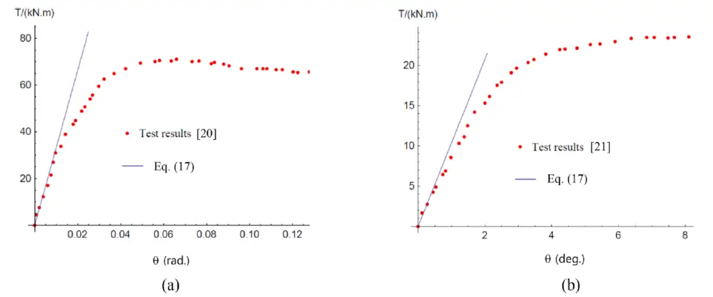
The calculated rigidity of the member, as determined from Eq. (3), is also plotted in Fig. 3(a) (with G = E/[2(1 + μ)] and μc = 0.2 for concrete and μs = 0.3 for steel) and can be seen to be in good agreement with the test result in the elastic range (i.e. up to about T = 40 kNm for the case shown). Similarly, good predictions of torsional rigidity (within about 12%) were achieved following comparisons with the experimental results reported in (Kitada and Nakai, 1991), as shown in Fig. 3(b), the key properties of which are provided in Table 1 above.
Comparison between test T-θ curve from (a) [Chen, 2003] and (b) [Kitada and Nakai, 1991] and Eq. (3). (Zhang et al, 2022)
Finite Element Verification
Additionally, the authors used finite element modelling to confirm the derived uniform torsional rigidity found in Eq. (3). Using SOLID65 and SHELL181 elements, respectively, for the core concrete and steel tube and concrete, a series of square CFST members were modelled in ANSYS software. Following a convergence study, an element size of 20 mm in all directions was chosen. To model the contact between the steel and the concrete, the contact elements TAGRE170 and CONTAL173 were employed.
At the tips of the members, a MASS21 mass element with rotational degrees of freedom was introduced to add torque, and all node degrees of freedom were constrained at the fixed ends of the members.
Twelve square CFST members with varying lengths and depths were modelled. Each member was made of a Q235 steel SHS outer tube (Es = 206 GPa and μs = 0.3) and a C40 concrete core (Ec = 32.4 GPa and μc = 0.2). Tip rotations were calculated using two methods:
(1) the FE models, which provided θL,FE; and (2) Eq. (3), which combined the uniform torsional rigidity (GJ)k provided by Eq. (3) to provide θL,SE (referred to as the “Theory”).
The results, along with the forecasts’ mean and standard deviation, are given in the Table below. The results show that the theoretical tip rotations and the finite element tip rotations correspond quite closely, with the largest absolute difference being less than 0.5%.
Statistical Sensitivity
The uniform torsional stiffness of a square CFST section and the sensitivity of the non-dimensional parameter to variations in the steel ratio and the ratio of the shear modulus of steel to that of concrete were also taken into consideration in the study. For a value of Es = 210 GPa and μs = 0.3, the shear modulus of steel is given by Gs = Es/[2(1 + μs)], which corresponds to a value of Gs ≈ 81 GPa. Depending on the concrete grade, the shear modulus of concrete Gc typically ranges from 12.5 GPa to 15.8 GPa. As a result, m virtually solely affects the grade of concrete, and its value falls between 5.1 and 6.4.
The relationship between Ψ and m for various steel ratios was displayed on a graph, and the following was noted:
(1) As α changes, the trend of the Ψ -m relationship remains similar, indicating that the relationship between Ψ and α is approximately linear (2) As m increases, Ψ decreases.
The Ψ -α relationship for different values of m showed that:
(1) As m changes, the trend of the Ψ -α relationship also remains similar indicating that the relationship between Ψ and m is approximately linear (2) As α increases, Ψ also increases.
Overall, it may be concluded that Ψ varies approximately linearly with both α and m, and that the influence of the steel ratio α is more significant.
Simplified Design Formula
The principle of superposition may be used now that it has been established that the relationships between ψ and both m and α are roughly linear. Consequently, the uniform torsional rigidity of a square CFST section can also be written as:
(GJ)ksup =(GJ)s +(GJ)c
where the first term is the torsional rigidity of a thin-walled square steel tube (GJ)s, and the second term is the torsional rigidity of a solid square concrete core (GJ)c.
The following results were reached after studying the uniform torsional rigidity of square concrete-filled steel tubular (CFST) sections:
It has been established that an analytical formula for determining the uniform torsional rigidity of square CFST sections yields highly precise predictions of the numerical data (within 0.5%). The findings of earlier experiments were accurately predicted as well.
It has been demonstrated that the uniform torsional stiffness varies roughly linearly with both the steel ratio and the ratio of the shear modulus of steel to concrete, with the steel ratio being more significant.
Continuing from (2), the uniform torsional rigidity of square CFST cross-sections has been satisfactorily simplified by the principle of superposition.
By combining the data provided here with those of previous researchers, a very accurate predictive model for the full range elastic-plastic torsion moment-deformation response of CFST members may be created.
The work that has been described can be expanded to examine the uniform torsional rigidity of CFST components with different cross-sectional forms.
Article Credit:
Zhang W. F., Gardner L., Wadee M.A., Chen K.S., Zhao W.Y. (2022): On the uniform torsional rigidity of square concrete-filled steel tubular (CFST) sections. Structures 43 (2022) 249–256. https://doi.org/10.1016/j.istruc.2022.06.046
The contents of the cited original article published by Cement and Concrete Research (Elsevier) is open access, under the CC BY license (http://creativecommons.org/licenses/by/4.0/) which allows you to share and adapt (remix) the article provided the appropriate credit is given, and the link to this license provided.
References
[1] Chen Y.W. (2003): Research on torsion and section behaviour of concrete-filled steel tubular columns. Taiwan Central University, 2003. [2] Kitada T, Nakai H. (1991): Experimental study on the ultimate strength of concrete-filled square steel short members subjected to compression or torsion. Proceedings of the Third International Conference on Steel Concrete Composite Structures. Fukuoka, Japan, 1991. [3] Timoshenko SP, Goodier JN. (1970): Theory of Elasticity. 3rd Edition, 1970, McGraw-Hill, New York. [4] Zhang W. F., Gardner L., Wadee M.A., Chen K.S., Zhao W.Y. (2022): On the uniform torsional rigidity of square concrete-filled steel tubular (CFST) sections. Structures 43 (2022) 249–256. https://doi.org/10.1016/j.istruc.2022.06.046
Structural elements subjected to axial compressive forces are described as either columns or struts. Columns are a fundamental load-carrying element typically oriented in a vertical direction within structures. Struts, on the other hand, represent a more general term encompassing any member experiencing compression. These elements can be found in various configurations, including vertical elements in building frames, the top chords of trusses, or indeed, any location within a three-dimensional space frame.
In structural members subjected to compressive forces (e.g. steel columns and struts), secondary bending caused by imperfections within materials during fabrication processes, inaccurate positioning of loads or asymmetry of the cross-section etc, can induce premature failure either in a part of the cross-section, such as the outstand flange of an I-section, or on the element as a whole. In such cases, the failure mode is predominantly buckling and not squashing.
The design of most steel column members is governed by their overall buckling capacity, i.e. the maximum compressive load which can be carried before failure occurs by excessive deflection in the plane of greatest slenderness.
Compression members (i.e. struts and columns) should be checked for; (1) resistance to compression (2) resistance to buckling
The design of steel columns for buckling is well covered in clause 4.7 of BS 5950-1:2000 while the buckling resistance of members is covered in clause 5.5 of EN 1993-1-1:1992 (EC3). The checks for uniform compression in EC3 are found in clause 5.4.4.
In the design of steel columns, the design compressive axial force (NEd) should not exceed the design compression resistance (Nc,Rd) such that;
NEd/Nc,Rd ≤ 1.0 Nc,Rd = (A.fy)/γmo
Where; A is the gross area of the section fy is the yield strength of the section γmo is the material factor of safety.
Similarly, the design axial force should not exceed the buckling resistance of the steel column (Nb,Rd) such that;
Nb,Rd = χAfy/γmo
Where; χ is the buckling reduction factor A is the gross area of the section fy is the yield strength of the section γmo is the material factor of safety.
Design Process of Steel Columns
Designing a steel column involves a systematic approach that balances strength, stability, and economy. Here’s a breakdown of the key steps:
Load Determination:
Identify all characteristic loads acting on the steel column, including dead loads (self-weight of the column, beams, and slabs), live loads (occupancy, furniture), and wind or seismic loads.
Apply appropriate load factors as per design codes (e.g., AISC 360 in the US, Eurocode 3 in Europe) to account for uncertainties and safety margins.
Define load combinations representing different scenarios (e.g., dead + live, dead + live + wind).
Material Properties:
Specify the steel grade for the column, considering its yield strength (fy) and ultimate strength (fu). Common grades include A36, A572, S275, S355, and high-strength steels.
Column Selection (Trial and Error):
Assume an initial steel section size (e.g., wide flange section – W shape, universal column UC section – H section, hollow structural section – HSS).
Calculate the effective length (Le) of the steel column, which considers the actual length and end conditions (pin-ended, fixed, etc.).
Determine the slenderness ratio (λ) by dividing the effective length by the radius of gyration (r) of the chosen column section. The radius of gyration is a geometric property that reflects the distribution of area within the section. Steel design codes provide tables for r values for various sections.
Compression Capacity:
Calculate the design load capacity (Nc,Rd) of the steel column for pure compression: Nc,Rd = fy × A
Buckling Capacity:
Evaluate the buckling capacity (Nb,Rd) of the steel column using design code provisions. This typically involves a buckling reduction factor (χ) that accounts for the column’s slenderness, type of section, and potential for inelastic buckling. The buckling capacity is generally expressed as: Nb,Rd = χ × fy × A (where A is the cross-sectional area)
Design codes provide charts or equations for determining χ based on the slenderness ratio.
Moment Capacity Checks (Optional):
For columns subjected to bending moments in addition to axial loads, perform additional checks to ensure adequate flexural strength. This may involve calculating the moment capacity of the section and comparing it with the design moment demands.
Capacity Checks:
Compare the factored design loads NEd (from step 1) with the steel column’s capacities (Nc,Rd and Nb,Rd). The design is safe if:
For all load combinations: NEd ≤ Nc,Rd
If the steel column is slender (high λ), buckling capacity (Nb,Rd) becomes the governing factor:
Factored Design NEd ≤ Nb,Rd
Iterative Process:
If the initial section fails the capacity checks, select a larger section and repeat steps 3-6. This iterative process continues until a suitable section is found that satisfies all design criteria.
Design Considerations
Connection Design: Ensure the steel column connections (welded, bolted) can transfer the forces safely to beams or other elements.
Fire Resistance: If the column is part of a fire-resisting structure, consider the impact of fire on its strength and stability. Fireproofing materials may be required.
Corrosion Protection: Depending on the environment, the column may require corrosion protection through painting, galvanizing, or other methods.
Tools and Resources
Steel design codes (AISC 360, Eurocode 3) provide detailed design procedures and design tables.
We can calculate the outstand of the flange (flange under compression) C = (b – tw – 2r) / (2 ) = (327.1 – 15.8 -2(15.2)) / (2 ) = 140.45 mm We can then verify that C/tf = 140.45/25 = 5.618 5.618 < 9ε i.e. 5.618 < 8.478.
Therefore the flange is class 1 plastic
Web (Internal compression) d/tw = 15.6 < 33ε so that 15.6 < 31.088. Therefore the web is also class 1 plastic Resistance of the member to uniform compression Nc,Rd = (A.Fy)/γmo = (201 × 102 × 265) / 1.0 = 5326500 N = 5326.5 kN
NEd/Nc,Rd = 3556/5326.5 = 0.6676 < 1
Therefore section is ok for uniform compression.
Buckling resistance of member (clause 5.5 EN 1993-1-1:1992)
Since the member is pinned at both ends, the critical buckling length is the same for all axis Lcr = 4000mm
In the major axis (¯λy ) = 4000/(139 × 88.454) = 0.3253 In the minor axis (¯λz ) = 4000/(79 × 88.454) = 0.5724
Check D/b ratio = 327.1/311.2 = 1.0510 < 1.2, and tf < 100 mm (Table 5.5.3 EN 1993-1-1:1992)
Therefore buckling curve b is appropriate for y-y axis, and buckling curve c for z-z axis. The imperfection factor for buckling curve b, α = 0.34 and curve c = 0.49 (Table 5.5.1)
Summarily, the section is ok to resist axial load on it.
Column Design According to BS 5950-1:2000
From Table 9 BS 5950-1:2000 Since the thickness of the flange is > 16mm but < 40mm, Py = 265 N/mm2 Obviously, the column will buckle about the z-z axis, which is the weaker axis in terms of buckling. It is however important to realise that axes are not labelled in the same way using the two codes. The z-z axis in EC3 is the y-y axis in BS 5950, while the y-y axis in EC3 is called the x-x axis in BS 5950.
Hence the UC section is not slender. Therefore, let us focus on the weaker axis (z-z) in order to verify the buckling load. Slenderness ratio = λ = Lcr/rz = 4000/79 = 50.633
From Table 23 of BS 5950, for H sections of thickness < 40mm, strut curve c is appropriate for calculating our compressive strength PC (N/mm2). We can go through the stress of calculating the compressive strength PC using the formulas outlined in ANNEX C of BS 5950 or simply read them from Table 24 of the code. We will use the two methods in this example.
Calculating using formula Limiting slenderness λ0 = 0.2 [(π2E)/Py ]0.5 = 0.2 [(π2 × 210000) / 265]0.5 = 17.6875
Perry factor for flexural buckling under axial load η = [a(λ – λ0)]/1000 where a = 5.5 for strut curve c η = [5.5(50.633 – 17.6875)] / 1000 = 0.1812 Euler load PE = (π2E)/λ2 = (π2 × 210000) / 50.6332 = 808.447 N/mm2 Φ = [Py + (η+1)PE] / 2 = [265 + (0.1812 + 1) × 808.447] / 2 = 609.9688 N/mm2 Therefore, the compressive strength Pc = (PE Py) / (Φ + (Φ2 – PE Py)0.5)
Pc = (808.447 × 265) / (609.9688 + [609.96882 – (808.447 × 265)]0.5) = 212.699 N/mm2 If we had decided to read from the chart, strut curve C, λ < 110, Py = 265 N/mm2 Knowing that λ = 50.633. Interpolate between λ = 50 and 52 to obtain Pc = 212 N/mm2 So let us use PC = 212.699 N/mm2 Hence Buckling load, PX = AgPc = 201 × 102 × 212.699 = 4275249.9 N = 4275.2499 kN
Therefore, N/PX = 3556/4275.2499 = 0.8317 < 1.0. Hence the section is okay for buckling.
The difference in result between EC2 buckling load (Nb,Rd = 4269.189 kN) and BS 5950 buckling load (PX = 4275.2499 kN) for axially loaded columns disregarding load factor is just about 0.144%.
You can download the paper HERE and compare the results from the two codes.
The effect of water pressures on the soils at the formation level can have a negative impact on a cofferdam‘s stability to the point where collapse may happen. Excessively high water pressure in granular soils results in piping, whereas it causes heaving in cohesive or extremely densely packed soils.
When the pressure exerted on the soil grains by the water flowing upward is so great that the effective stress in the soil is close to zero, piping occurs. The soil in this circumstance lacks shear strength and transforms into a state that might be compared to quicksand, making it incapable of supporting any vertical weight. When this occurs, the cofferdam workers are obviously in a highly risky situation, and the soil’s passive resistance to the cofferdam wall will also be significantly reduced.
In extreme circumstances, this may result in the cofferdam failing and the wall losing all support. By constructing a flow net, an engineer may predict the chance of piping for a specific cross section and determine the exit hydraulic gradient. The factor of safety against piping will be revealed by comparing the estimated value to the critical hydraulic gradient; for clean sands, this should typically lie between 1.5 and 2.0.
When designing circular cofferdams and the corners of rectangular constructions, care should be taken because these situations present more of a three-dimensional challenge than a long wall would. Installing the sheet piles at a deeper depth increases the flow path and lowers the hydraulic gradient, enhancing the factor of safety against piping.
Minimum cut-off depth in cofferdams (ArcelorMittal, 2008)
Width of cofferdam (W)
Depth of cut-off (D)
2H or more
0.4H
H
0.5H
0.5H
0.7H
If the force of the water pressure acting on a block of material inside the cofferdam exceeds the bulk weight of the block, base heave may happen. This can happen in cohesive or very tightly packed granular material. Using a flow net, it is possible to determine the average water pressure acting on the line drawn between the piles and translate it to an uplift force acting on the soil plug inside the cofferdam in order to determine the likelihood of heave.
The groundwater level can be lowered using well points outside of the cofferdam to lessen the flow of water into the structure. As an alternative, pumping from well sites inside the cofferdam that is at or below pile toe level can minimize flow into the structure. However, it should be kept in mind that when a cofferdam’s stability or convenience of use depends on pumping, the dependability of the pumps is crucial, and backup capacity must be available to handle any problems.
Flow nets in Cofferdams
The construction of flow nets is a helpful tool because it gives the engineer a visual depiction of the soil’s flow regime and the ability to compute the water pressures in a specific situation. The following notes show how a net can be drawn given uniform soil conditions and permeability. The shape and complexity of a flow net depend on the homogeneity and permeability of the soil.
• A scaled cross-section drawing of the problem should be produced. • A datum level should be marked on the cross-section either at an impermeable boundary or at a suitable level below the cofferdam. • The flow criteria must be determined. • External water level. • Internal water level. • Centre line of cofferdam (this is the axis of symmetry). • Lines of flow must be parallel to the cofferdam walls and the impervious datum.
The net is created using flow lines and equipotential lines using the aforementioned guidelines (a standpipe at any point on an equipotential line would register the same height H above the datum level). These are roughly square-shaped and at right angles to one another. Trial and error is a big part of this procedure, but with practice, you’ll be able to construct the flow net reasonably quickly and accurately.
Typical flow net for a cofferdam (ArcelorMittal, 2008)
In order to determine the pore water pressure ‘u’ at any location (using the example above);
• Determine the probable head ‘H’ at the targeted location (note that the potential head drop is always the same between successive equipotential lines once a square net has been formed)
H = H1 – (H1 – H2) × n/Nd
where; n = number of equipotential drops to the point being considered Nd = total number of drops
Hence at point A, H = H1 – (H1 – H2) × (2/10)
• At any point H = u/γw + z
where; u = pore water pressure γw = density of water z = height of point above datum
As H, γwand z are known, u can be calculated; u = (H – z) × γw
Flow nets can also be used to estimate the approximate volume of water flowing around the toes of the piles into the cofferdam. The flow volume ‘Q’ m3/s per metre run of wall is given by;
Q = k(H1 – H2) × Nf/Nd
where; k = coefficient of permeability of the ground (m/s) H1 – H2 = total head drop (m) Nf = number of flow channels (in half width of cofferdam) Nd = number of potential drops
The factor of safety against piping
The “exit hydraulic gradient” right below the formation level inside the cofferdam can be calculated using the flow net. The hydraulic gradient ‘i‘ (which is dimensionless), is the loss of head per unit length in the direction of flow. The exit gradient (ie) in the aforementioned case is represented by;
ie = [(H1 – H2)/Nd] × (2Nf/B)
Where; B/2Nf is the width of each exit flow net square since B/2 is the half-width of the cofferdam Nf is the number of flow channels in the half-width of the cofferdam
The critical hydraulic gradient at which piping takes place and the effective soil stress drops to zero for ground with a saturated bulk weight of around 20 kN/m3 is ic = 1.0. The factor of safety against piping is defined as;
FoS = ic/ie, which roughly equals (1.0/ie).
A flow net like the one used as an example is merely a section of a very long cofferdam. The 3-dimensional nature of the flow has the effect of further concentrating the head loss within the soil plug between the sheet pile walls for square or circular cofferdams. The head loss per field on the inside face of the cofferdam should be corrected using the following correction factors:
Circular cofferdams = parallel wall values x 1.3 In the corners of a square cofferdam = parallel wall values x 1.7
For clean sands, the factor of safety against piping (1.0/ie)should be between 1.5 and 2.0