8.7 C
New York
Friday, June 6, 2025
Home Blog Page 36

Design of Reinforced Concrete (R.C.) Slabs

Reinforced concrete (R.C.) slabs are plate elements used to form the floors of buildings. In a typical reinforced concrete building, reinforcement bars arranged as mats are incorporated into a concrete plate of minimum thickness 125 mm to form a reinforced concrete solid slab. The provision of adequate reinforcement, slab thickness, and proper detailing to satisfy ultimate and serviceability limit state requirements forms the basis of the design of reinforced concrete (R.C.) slab. Satisfying other requirements such as durability, fire resistance, etc are also necessary.

Floor slabs are usually subjected to uniformly distributed loads, partially distributed loads, line loads, or concentrated loads in the transverse direction. A beam is similar to a slab in so many ways but there are fundamental differences in behaviour and stress distribution of the two elements. While a beam is generically a one-dimensional element, a plate is a two-dimensional element. Due to the two-dimensional nature of a slab, it is subjected not only to bending moments Mxx and Myy and shear forces Vx and Vy but also to twisting moments Mxy on all the four faces.
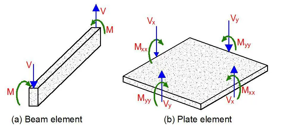
Beam and plate element
Fig 1: Beam element and slab element

Types of Reinforced Concrete Slabs

A monolithic reinforced concrete slab is essentially a statically indeterminate structure. For a slab of a given shape and support conditions, the distribution of shear forces, bending, and twisting moments in the slab due to externally applied loads cannot be determined easily. The column layout in a monolithic reinforced concrete structure often forms a rectangular grid. Continuous beams may be provided in one direction or two orthogonal directions, to support slabs that may be solid or ribbed in cross-section. Alternatively, slabs can be supported directly on columns to form flat slabs.

Slabs may be simply supported or continuous over one or more supports and are classified according to the method of support as follows:

  1. One-way spanning slab between beams or walls
  2. Two-way spanning slab between the support beams or walls
  3. Flat slabs carried on columns and edge beams or walls with no interior beams
  4. Ribbed slab transferring slab load to beams and walls in one direction
  5. Waffle slab transferring slab load to beams and slabs in two direction

One-way Spanning Solid Slabs

Clause 5.3.1(5) of EN 1992-1-1:2004 suggests that a slab subjected dominantly to uniformly distributed loads may be considered as one-way spanning if either:

  1. It possesses two free (unsupported) and sensibly parallel edges.
  2. It is the central part of a sensibly rectangular slab supported on four edges with a ratio of longer (Ly) to shorter span (Lx) greater than 2.
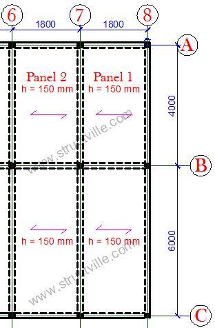
One way slab arrangement
Fig 2: Typical general arrangement of a one-way slab system

In other words, when beams are provided in one parallel direction only, the slab is a one-way slab. Furthermore, if the longer side of a slab panel exceeds twice the shorter side, the slab is generally designed as a one-way slab, but that does not mean that the slab is transmitting load in one direction only.

One-way slabs may be simply supported or continuous. For one-way slabs supported on two opposite sides, the bending moments are calculated in the same way as for beams. Continuity across a beam is treated as fixed support. In detailing, if a slab is assumed to be simply supported at an end support, it is advisable to provide reinforcement for a probable negative bending moment due to the monolithic construction of beams and slabs (Reynolds and Steedman, 2005).

Typical detailing of a one-way simply supported reinforced concrete slab
Fig 3: Typical reinforcement detailing of a simply supported one-way slab

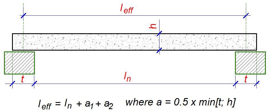
The effective span for one-way slabs is the same as that of beams. If ln is the clear span (distance between faces of supports), the effective span leff is given by;

leff = ln + a1 + a2
effective length of one way slabs 1
Fig 4: Effective span of a simply supported one-way slab

One-way slabs should be designed to resist the most unfavourable arrangement of loads. In clause 5.1.3 of Eurocode 2, the following two loading arrangements are recommended for buildings.

  1. Alternate spans carrying (γGGk + γQQk) other spans carrying only γGGk.
  2. Any two adjacent spans carrying (γGGk + γQQk). All other spans carrying only γGGk

Steps in the design of a one-way slab

The steps in the design of a slab are as follows;

  1. Determine the design life of the structure
  2. Choose a slab thickness determined using deflection requirements, experience, or otherwise
  3. Establish the durability requirements, fire resistance, and adequate concrete cover
  4. Calculate and apply the loads on the slab comprising of the dead and imposed loads
  5. Apply the appropriate load combination
  6. Idealise each slab element and analyse to determine the critical design moments MEd and shear forces VEd
  7. Carry out the flexural design
  8. Check the deflection
  9. Check the shear capacity
  10. Check bar spacing and cracking

For the flexural design of slabs, determine k from;

k = MEd/(fckbd2)
If k < 0.167, no compression reinforcement is required, and you can calculate the lever arm;
z = d[0.5 + √(0.25 – 0.882k)]

The area of reinforcement required is given by;
As1 = MEd/(0.87fykz)

(a) Concrete cover
The nominal concrete cover in slabs is expected to satisfy the requirement;

Cnom = Cmin + ∆c,dev

Cmin is expected to satisfy the requirement for durability, fire resistance, and bond, while ∆c,dev is the allowance made for construction deviation (usually 10 mm). The minimum cover for bond should not be less than the bar diameter. For a one-way slab to have a fire rating of one hour (REI 60), the minimum thickness should be 80 mm and the concrete cover (from the surface to the centre of bar) should be minimum of 20 mm. A minimum cover of 15mm + ∆c,dev is adequate for the durability of slabs under exposure class XC1. Therefore under normal circumstances, a concrete cover of 25 mm is usually adequate for floor slabs.

(b) Minimum tension steel
The main moment steel spans between supports and over the interior supports of a continuous slab. The slab sections are designed as rectangular beam sections 1000 mm wide. The minimum area of main reinforcement has to satisfy clause 9.2.1.1(1) of Eurocode 2;

As,min = (0.26fctm/fyk)btd but not less than 0.0013bd

where bt = width (for slab design 1000 mm), d = effective depth

The maximum area of steel provided should not exceed 0.04Ac.

(c) Distribution steel
The distribution, transverse, or secondary steel runs at right angles to the main moment steel and serves the purpose of tying the slab together and distributing non-uniform loads through the slab. Clause 9.3.1.1(2) states that in the case of one-way slabs, secondary reinforcement of not less than 20 percent of principal reinforcement should be provided. Note that distribution steel is required at the top parallel to the supports of continuous slabs. The main steel is placed nearest to the surface to give the greatest effective depth.

detailing of continuous one way slab
Fig 5: Typical reinforcement detailing of a continuous one-way slab

(d) Slab main reinforcement
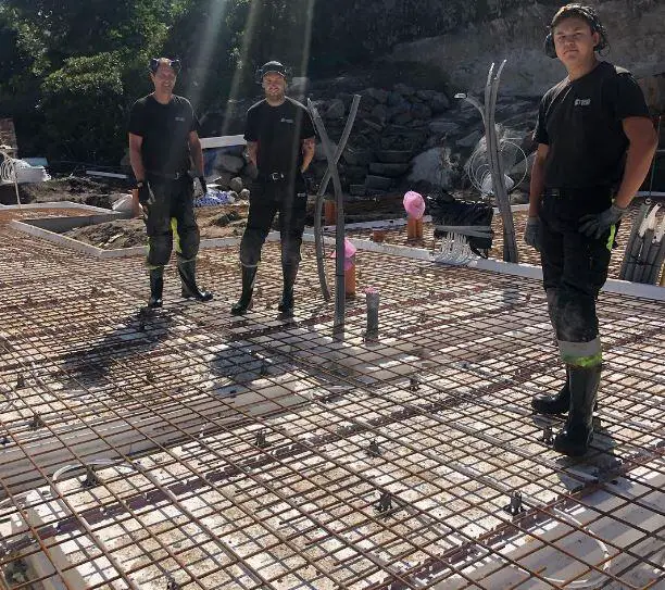
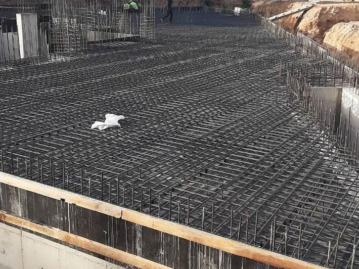
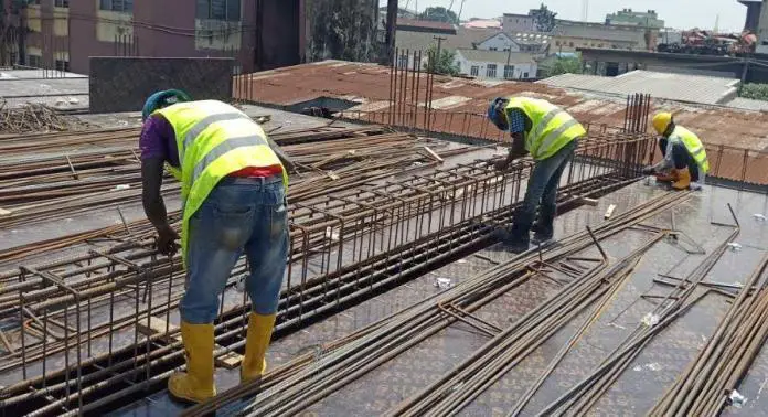
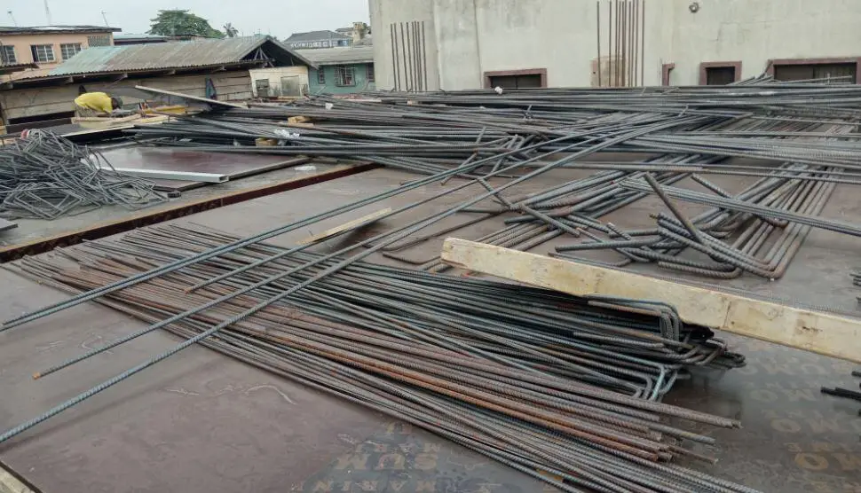
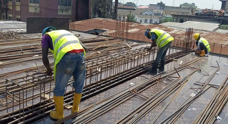
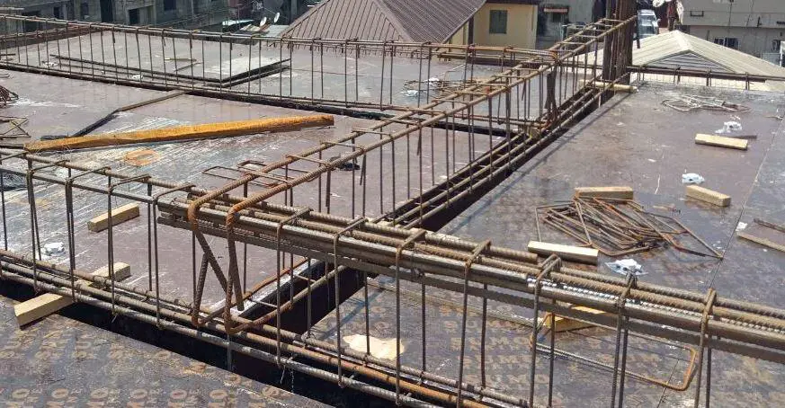
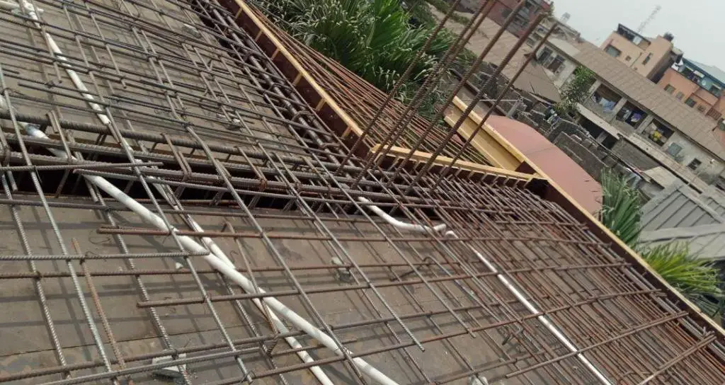
Slab reinforcement is a mesh and may be formed from two sets of bars placed at right angles. The table below gives bar spacing data in the form of areas of steel per metre width for various bar diameters and spacings. Reinforcement in slabs consists of a large number bars both ways which need to be tied together to form a mat. This is actually an expensive operation (see cost of fixing reinforcement in Nigeria).

It is necessary to point out that the critical span in the analysis of solid slabs is the short span. Therefore, the main reinforcements will lie parallel to the short span, and that is where you check your deflections (see why short spans are critical in floor slabs).

Table 1: Area of reinforcement per metre width of spacing

Spacingϕ8 mmϕ10 mmϕ12 mmϕ16 mmϕ20 mm
100502 785113020103141
12540262890416082513
15033552375313402094
17528744864611481795
20025139256510051570
2252233495028931396
2502013144528041256
2751822854117311142
3001672613766701047

For instance, if the area of reinforcement required (As,req) from calculation is 523 mm2/m, you can provide H12@200 c/c (Area of steel provided As,prov = 565 mm2/m).

(e) Crack Control
According to Clause 9.3.1.1(3) of Eurocode 2, if h is the total depth of the slab, then the maximum spacing of reinforcements is normally restricted to;

  • 3h ≤ 400 mm for principal reinforcement
  • 3.5 h ≤ 450 for secondary reinforcement

However, in areas of maximum moment, maximum spacing is restricted to;

  • 2h ≤ 250 mm for principal reinforcement
  • 3 h ≤ 400 mm for secondary reinforcement

For slabs 200 mm thick or greater the bar size and spacing should be limited to control the crack width and reference should be made to section 7.3.3 of the Eurocode 2.

(f) Curtailment of bars in slabs
Curtailment of bars is done according to the moment envelope. However, clause 9.3.1.2(1) requires that half the calculated span reinforcement must continue up to support. It is further stated that in monolithic construction, where partial fixity occurs along an edge of a slab but is not taken into account, the top reinforcement should be capable of resisting at least 25 percent of the maximum moment in the adjacent span and this reinforcement should extend at least 0.2 times the length of the adjacent span measured from the face of the support.

simplified curtailment rules of floor slabs
Fig 6: Typical curtailment rules of solid slabs

The above situation occurs in the case of simply supported slabs or the end support of a continuous slab cast integral with an L-beam which has been taken as a simple support for analysis but the end of the slab might not be permitted to rotate freely as assumed. Hence negative moments may arise and cause cracking.

(g) Shear capacity of slabs
Under normal loads, shear stresses are not critical and shear reinforcement is not required in floor slabs. Shear reinforcement is provided in heavily loaded thick slabs but should not be used in slabs less than 200 mm thick (clause 9.3.2 (1)). To check the shear capacity of slabs, the shear stress (vEd = VEd/bd) must be checked against the shear capacity of an unreinforced section (VRc,d). This is given by;

VRd,c = [CRd,c k(100ρ1 fck )1/3 + k1cp] ≥ (Vmin + k1cp)

Where;
CRd,c = 0.18/γc
k = 1 + √(200/d) < 0.02 (d in mm);
ρ1 = As1/bd < 0.02 (In which As1 is the area of tensile reinforcement which extends ≥ (lbd + d) beyond the section considered)
Vmin = 0.035k(3/2)fck0.5
K1 = 0.15; σcp = NEd/Ac < 0.2fcd
(Where NEd is the axial force at the section, Ac = cross sectional area of the concrete), fcd = design compressive strength of the concrete).

In a one-way slab, the design shear force is calculated from the support reactions or end-shears at the support, while in a two-way slab, they can be obtained from the coefficients in Table 3.15 of BS 8110-1:1997.

(h) Check for deflection
The check for deflection is a very important consideration in slab design and usually controls the slab depth. In normal cases, a strip of slab 1 m wide is checked against span-to-effective depth ratios. A slab should not deflect excessively under service load. Excessive deflection of slabs can cause cracking to partitions and finishes.

For deemed to satisfy basic span/effective depth (limiting to depth/250);

Actual L/d of the slab must be ≤ Limiting L/d × βs

The limiting basic span/ effective depth ratio is given by;

L/d = K [11 + 1.5√(fck0/ρ + 3.2√(fck) (ρ0/ρ – 1)1.5] if ρ ≤ ρ0

L/d = K [11 + 1.5√(fck) ρ0/(ρ – ρ’) + 1/12 √(fck) (ρ0/ρ)0.5 ] if ρ > ρ0

Where;
L/d is the limiting span/depth ratio
K = Factor to take into account different structural systems
ρ0 = reference reinforcement ratio = 10-3 √(fck)
ρ = Tension reinforcement ratio to resist moment due to design load
ρ’ = Compression reinforcement ratio

The value of K depends on the structural configuration of the member and relates the basic span/depth ratio of reinforced concrete members. This is given in the table 2;

Table 2: Basic span/effective depth ratio of different structural systems

Structural SystemKHighly stressed ρ = 1.5%Lightly stressed ρ = 0.5%
Simply supported slabs1.01420
End span of interior slabs1.31826
Interior span of continuous slabs1.52030
Flat slab1.21724
Cantilever slabs0.468

βs = (500As,prov)/(fykAs,req)

Two-way Spanning Slabs

Two-way action occurs when a slab is supported on all four sides. If the two dimensions and support conditions are the same, then the load is distributed to all supporting beams equally. In design, a slab is considered to be two-way if the ratio of the longer side to the shorter side is less than two.

For two way slabs, the precise amount and distribution of the load taken by each support, and consequently the magnitude of the bending moments on the slab, are not easily calculated if assumptions resembling real conditions are made. Therefore, approximate analyses are generally used. The method applicable in any particular case depends on the shape of the slab panel, the conditions of restraint at the supports and the type of load.

Two basic methods are commonly used to analyse slabs that span in two directions. They are;

  1. The theory of plates, which is based on elastic analysis, is particularly appropriate to the behaviour under service loads
  2. Yield-line theory, which considers the behaviour of the slab as a collapse condition approaches.

Generally, for rectangular slabs with standard edge conditions and subject to uniformly distributed loads, normally the bending moments are obtained using tabulated coefficients. These coefficients are based on elastic analysis from thin plate theory. The loads used in the analysis are factored to represent the ultimate limit state condition. This is the approach used in BS 8110 for slabs with corners that are not held down (no consideration for torsion). The analysis must take into account the support conditions which can be idealised as fixed, hinged, or free.

For slabs with irregular plan shapes and slabs subject to a combination of point loads and distributed loads, Johansen’s yield line analysis and the Hillerborg strip method provide powerful methods for strength calculations.

Simply supported two-way slabs
Where the corners of slabs are free to lift and no provision is made to resist forces at the corners, the maximum moments per unit width are given by the following expressions:

Msx = bending moment in strips with span lx = Msx = αsxqlx2
Msy = bending moment in strips with span ly = Msy = αsyqlx2

where lx is the shorter span of the panel, ly is the longer span of the panel and q is the design ultimate load per unit area. Values of αsx and αsy are given in Table 3.13 of BS 8110-1:1997 for different ratios of ly and lx, where ly is the longer span.

Rectangular panels with restrained edges
Where corners of a two-way slab are prevented from lifting and reinforced to resist torsion, the maximum bending moments per unit width are given by the following expressions:

Msx = βsxqlx2
Msy = βsyqlx2

where;
Msx is the maximum design moment either over supports or at midspan on strips with span lx
Msy is the maximum design moment either over supports or at midspan on strips with span ly
q is the design ultimate load per unit area,
lx is the shorter span, and
ly is the longer span

The coefficients can be obtained from Table 3.14 of BS 8110-1:1997.

Design Example of a two-way slab

The general arrangement of the floor plan of a building is shown below. Design and detail the panel 1 of the building using the following data;

Thickness of floor slab = 150 mm
Concrete cover = 25 mm
Characteristic variable load = 1.5 kN/m2
fck = 25 N/mm2
fyk = 460 N/mm2
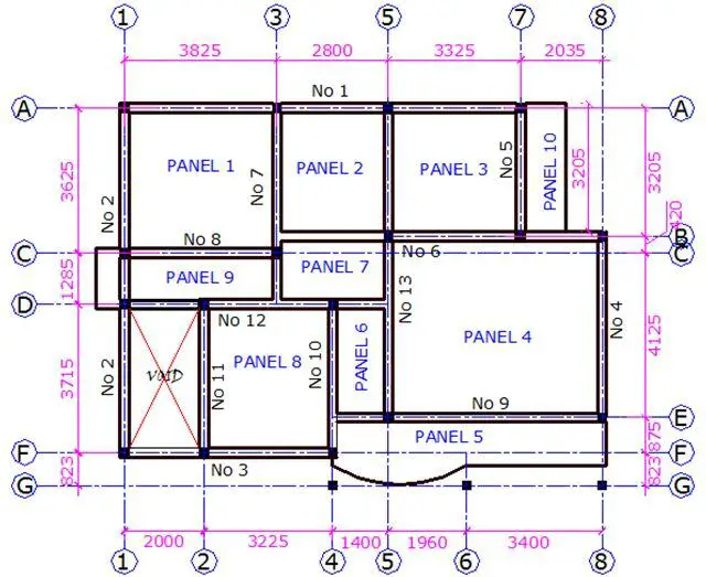
General arrangement of building
Fig 7: General arrangement of a floor slab

Load Analysis of Panel 1

Permanent Loads
Self weight of slab = 25 kN/m3 × 0.15m = 3.75 kN/m2
Weight of finishes = 1.2 kN/m2
Partition allowance = 1.5 kN/m2
Total dead load (gk)  = 6.45 kN/m2

Variable Load on slab
Leading variable action (Imposed load) qk1 = 1.5 kN/m2

Total load on slab (ULS) = 1.35gk + 1.5qk = 1.35(6.45) + 1.5(1.5) = 10.9575 kN/m2

The floor slab (PANEL 1) is spanning in two directions, since the ratio (k) of the longer side (ly) to the shorter side (lx) is less than 2. Hence, k = Ly/Lx = 3.825/3.625 = 1.055 (say 1.1, however it is more appropriate to interpolate from the table).

Moment coefficient for two adjacent edges discontinuous

Short Span
Mid-span = 0.042
Continuous edge = 0.056

Long Span
Mid-span = 0.034
Continuous edge = 0.045

Design of short span
Mid span
MEd = αnlx2 = 0.042 × 10.9575 × 3.6252 = 6.0475 kNm/m
d = h – Cc – ϕ/2

Assuming ϕ12mm bars will be employed for the construction
d = 150 – 25 – 6 = 119mm; b = 1000mm (designing per unit width)

k = MEd/(fckbd2) = (6.0475 × 10⁶)/(25 × 1000 × 1192) = 0.0171

Since k < 0.167 No compression reinforcement required

z = d[0.5 + √(0.25 – 0.882k)]
z = d[0.5 + √(0.25 – 0.882 × 0.0273)] = 0.95d

As1 = MEd/(0.87fykz) = (6.0475 × 10⁶)/(0.87 × 460 × 0.95 × 119) = 133.668 mm2/m

Provide Y12mm @ 250mm c/c BOT (ASprov = 452 mm2/m)

To calculate the minimum area of steel required;
fctm = 0.3 × fck2⁄3 = 0.3 × 252⁄3 = 2.5649 N/mm2 (Table 3.1 EC2)

As,min = 0.26 × fctm/fyk × b × d = 0.26 × 2.5649/460 × 1000 × 144 = 208.76 mm2/m
Check if As,min < 0.0013 × b × d (187.2 mm2/m)
Since, As,min = 187.2 mm2, the provided reinforcement is adequate.

Check for deflection
We check for deflection at the short span of slabs
k = 1.3 for slab simply supported at one end and continuous at the other end

ρ = As/bd = 134/(1000 × 119) = 0.001126 < 10-3√fck (0.005)

Since ρ < ρ0
L/d = K [11 + 1.5√(fck ) ρ0/ρ + 3.2√(fck) (ρ0/ρ – 1)3⁄2]

L/d = 1.3 [11 + 1.5√(25) × 0.005/0.001126 + 3.2√25 (0.005/0.001126 – 1)3⁄2] = 1.3(44.3 + 102.106) = 190.327


Modification factor βs = 310/σs
σs = (310fykAs,req)/(500As,prov) = (310 × 460 × 133.688)/(500 × 452) = 84.341 N/mm2
βs = 310/84.342 = 3.67 > 2.0 (take 2.0)

Taking the distance between supports as the effective span, L = 3625mm
The allowable span/depth ratio = βs × 30.838 = 2.0 × 190.327 = 280.645
Actual deflection L/d = 3625/119 = 30.462
Since 280.645< 30.462 Therefore, deflection is ok.

Shear Verification
Maximum shear force coefficient for slab(β) = 0.44
VEd = βnlx

Ultimate shear force VEd = 0.44 × 10.9575 × 3.625 = 17.477 kN/m

VRd,c = [CRd,c.k. (100ρ1 fck)1/3

CRd,c = 0.18/γc = 0.18/1.5 = 0.12

k = 1 + √(200/d) = 1 + √(200/119) = 2.296 > 2.0, therefore, k = 2

ρ1 = As/bd = 452/(1000 × 119) = 0.003798 < 0.02; K1 = 0.15

VRd,c = [0.12 × 2 × (100 × 0.003798 × 25)1/3] × 1000 × 119 = 60476.947 N = 60.476 kN

Since VRd,c (60.476 kN) > VEd (17.477 kN), no shear reinforcement is required.

Note that shear reinforcements are rarely required in solid slabs supported by beams. Hence no further checks for shear will be done on the slab.

Design of short span

Continuous edge
MEd = αnlx2 = 0.056 × 10.9575 × 3.6252 = 8.0633 kNm/m
Using the procedure described above;
k = 0.0228; La/d = 0.95; As1 = 178.2236 mm2; As,min = 172.5217 mm2
Provide Y12 @ 250mm c/c Top (As,prov = 452 mm2)

Design of long span
Mid span
MEd = αnlx2 = 0.034 × 10.9575 × 3.6252 = 4.895 kNm/m
k = 0.0138; La/d = 0.95; As1 = 108.1945 mm2; As,min = 172.5217 mm2;
Provide Y12 @ 250mm c/c N/Bottom (As,prov = 452 mm2)

Continuous edge
MEd = αnlx2 = 0.045 × 10.9575 × 3.6252 = 6.479 kNm/m
k = 0.0183; La/d = 0.95; As1 = 143.2057 mm2; As,min = 172.5217 mm2;
Provide Y12 @ 250mm c/c Top (As,prov= 452 mm2)

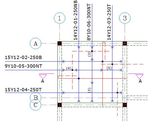
Reinforcement Detailing
detailing of floor slab
Fig. 8: Detailing of Panel 1
detailing of section


Cost of Reinforcement Works in Nigeria

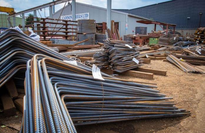
Installation of reinforcements is an important item of work in the construction of reinforced concrete structures. The cost of reinforcement works therefore significantly impacts the total contract sum of any construction project. In the preparation of a bill of quantity (BOQ) or bill of engineering measurement and evaluation (BEME), concrete and reinforcement works are listed as separate items of work.

Therefore, a contractor bidding for such a job is expected to provide his rate of buying, cutting, bending, and installing the reinforcements according to the construction drawing in one sum. While concrete is priced per cubic meters (m3), reinforcement is usually priced per kilogram (kg).

The price to be quoted per kg of reinforcement is expected to cover the cost of purchase and supply of the materials to the site, cost of cutting, bending, and installation according to the design specification. It is also expected to cover the contractor’s profit and overhead. The use of bar bending schedule (BBS) can enhance the process of reinforcement handling and evaluation.

Read Also…
How to quote/price for concrete in Nigeria

Therefore, a contractor bidding for a job in reinforced concrete construction is expected to know the basic cost of reinforcement in the market, the cost of transportation, the cost of labour, and the cost of machinery that will be needed to execute the job. Initial market research may be required before the tender is computed and submitted to the client.

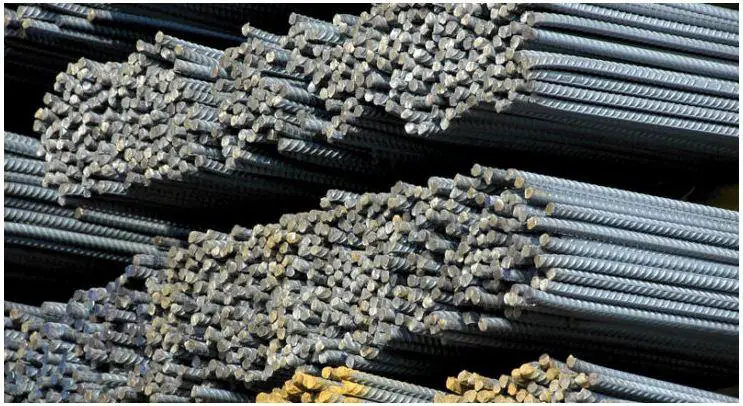
In Nigeria, there are different categories of reinforcements that are used for construction works, and each of them is priced differently in the market. As found all over the world, the use of mild steel (fy = 250 N/mm2) is no longer common, and it is rarely utilised in construction in Nigeria. However, some people still use R6mm (commonly called the ‘quarter rod’) and R8mm as links for columns and beams, but it is rarely specified in construction drawings these days. The categories of reinforcements in the Nigerian markets are;

  • Local reinforcements (manufactured locally)
  • TMT reinforcements (manufactured locally)
  • Foreign reinforcements (imported into the country)

Local reinforcements are manufactured locally by the steel industries in Nigeria and are the cheapest class of reinforcements in the market. They have a reputation of not always meeting the minimum yield strength requirements, and are not usually employed in large-scale or serious projects.

Cost of Reinforcement Works in Nigeria

TMT reinforcements are high-quality reinforcements produced from recycled steel through the process of thermomechanical treatment. They usually satisfy the yield strength requirements and are widely used for all kinds of projects in the country, including bridges. They are more expensive than local reinforcements. As at July 2022, while one tonne of reinforcement is sold at about ₦415,000.

Foreign reinforcements are usually imported from Germany, Ukraine, or Russia, and are slightly more expensive than TMT reinforcements. However, the presence of TMT reinforcements is making foreign reinforcements less attractive.

Therefore, careful attention to design details and specifications is needed during the pricing of reinforcements. We are going to show below the process of pricing for reinforcement works in Nigeria. The information that will be needed for the evaluation of the cost of reinforcement works in Nigeria are as follows;

  • Cost of reinforcement in the market (based on the size and type of reinforcement)
  • Cost of binding wire
  • Cost of delivery to site
  • Cost of labour for cutting, bending, and installation
  • Cost of machinery (cutting machine and bending machine)

Calculation of the Cost of Reinforcement Works in Nigeria

For example, let us calculate the cost of installing 3650 kg of Y12 reinforcements in the floor slab of a building.

rebar slab

As a rule of thumb, about 12 kg of binding wire is required to tie 1 tonne of reinforcement (this also means that about 0.012 kg of binding wire is required to tie 1 kg of reinforcement). Therefore about 44 kg of binding wire is required for this project.

Cost calculation
Basic cost of reinforcement (including delivery to site) = say ₦430,000 per tonne = ₦430 per kg
Basic cost of binding wire (including delivery to site) = ₦17,000 per 20 kg = ₦ 850 per kg (= ₦10.2 per kg of reinforcement)
Basic cost of labour (cutting, bending, and installation) = ₦25,000 per tonne = ₦25 per kg
Assuming that the use of machinery is not applicable in the project or factored into the cost of labour, total basic cost = 430 + 10.2 + 25 = ₦465.2 per kg

Make 10% allowance for waste and laps = 1.1 x 465.2 = ₦512
Allow 20% for contractor’s profit and overhead = 1.2 x ₦465.2 = ₦ 559 per kg

Therefore the current cost of reinforcement works in Nigeria is ₦559 per kg of reinforcement.

Therefore, the cost of fixing the floor slab reinforcement = ₦559 x 3650 = ₦2,040,350:00 (Two million, forty-six thousand and three hundred and fifty Naira)

For your construction and building design works, contact;

Structville Integrated Services Limited (RC 1491828)
Whatsapp/Call: +2347053638996
E-mail: info@structville.com

Design of Shear Walls

Shear walls are structural members that provide additional lateral stiffness to a building by resisting shear, moment, and axial forces, which are produced due to gravity and lateral loads. In some design cases, the entire lateral loads coming to a building assumed to be resisted by shear walls alone, especially when it is the major stabilising/bracing component of the building. The design of shear walls involves providing adequate cross-section and reinforcements to resist bending, shear, axial, and twisting forces due to gravity and lateral loads.

For an element to be described as a reinforced concrete wall, the length to thickness ratio should be equal to or greater than 4 (Clause 9.6.1, Eurocode 2). A shear wall is said to be short when the height-to-width ratio is less than or equal to one, while it is said to be slender when the height-to-width ratio is greater than or equal to four. For slender walls, bending deformation is dominant, while in short walls, shear deformation is dominant. When the height-to-width ratio is in-between one and four, then the shear wall undergoes both shear and bending deformations.

shear walls and columns in a building
Shear walls and columns in a building

Forces Acting on Shear Walls

Shear walls are designed to resist bending moment, shear, axial, and uplift forces, especially when they are subjected to lateral actions. The lateral forces acting in the plane of a shear wall attempts to lift up one end of the wall and push the other end down. Uplift forces are greater on tall walls and less on low walls. Shear walls resist the shear force parallel to the plane of the wall by cantilever action.

Axial forces in a Shear wall
The axial load in a wall may be calculated assuming the beams and slabs transmitting the loads to it are simply supported.

Transverse moments
For continuous construction, transverse moments can be calculated using elastic analysis. The eccentricity is not to be less than h/30 or 20 mm where h is the wall thickness.

In-plane moments
Moments in the plane of a single shear wall can be calculated from statics. When several walls resist forces, the proportion allocated to each wall should be in proportion to its stiffness.

Location/Placement of Shear of Shear Walls

In a tall building where the shear wall is used for lateral stability, it should be located on each level of the structure. Preferably, shear walls of equal length should be placed symmetrically on all four exterior walls of the building to form an effective box structure. When the shear walls in the exterior frame could not provide sufficient strength and stiffness, the shear walls should be added to the interior frame as well.

If the shear wall is placed at the interior frame of a building, it attracts and resists higher internal forces but may not be too effective in reducing the maximum lateral deflection of the building. However, if a shear wall is placed at the ends of a building, the lateral deflection is reduced considerably when compared to the later.

Architectural disposition in a building may not always give the room for optimum placement of shear walls for good structural performance. In some areas such as lift areas or window/door openings, coupled shear walls may have to be used. However, the best position or arrangement of shear walls in a building is a symmetrical arrangement whereby the shear centre (centre of rotation) will coincide with the centre of gravity of the building in order to reduce or eliminate torsion (twisting) due to lateral loads.

pierced shear wall
Coupled shear wall in a building

Functions of Shear Walls

  • Shear walls must provide the necessary lateral strength to resist horizontal wind and earthquake forces.
  • They provide resistance against sliding through connections.
  • They also provide lateral stiffness to prevent the roof or floor above from excessive side sway.
  • When the shear walls are stiff enough, they prevent floor and roof framing members from moving off their supports.
  • Buildings that are sufficiently stiff usually suffer less structural damage due to the presence of shear walls.


Structural Action of a Shear Wall

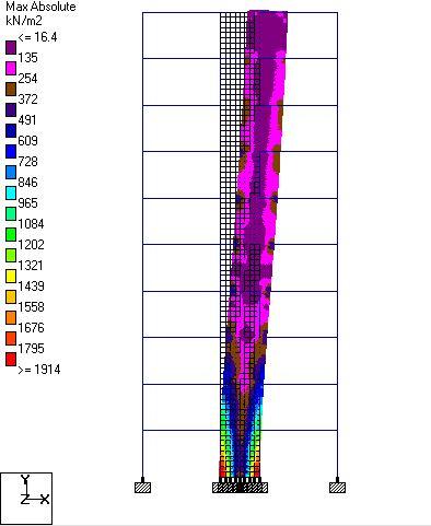
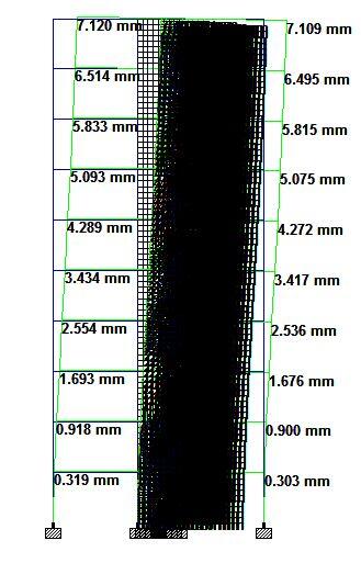
In a shear wall, the primary mode of deformation is mainly due to flexure but not shear. The mode of deformation of shear walls is such that it has maximum slope at the top and least at the bottom which is the flexural mode shape. The structural action of a shear wall resembles that of a cantilever beam.

Displaced shape of a shear wall under lateral load
Typical deflected shape of a shear wall

Structural Design of Shear Walls

The amount of reinforcement needed for proper detailing of a reinforced concrete wall may be derived using strut-and-tie model. If a wall is however subjected predominantly to out-of-plane bending, the design rules and guidelines for slabs apply. In Eurocode 2, the requirements for the design of columns and shear walls are not so different except in the following areas;

■ The requirements for fire resistance
■ Bending will be critical about the weak axis
■ Rules for spacing and quantity of reinforcement

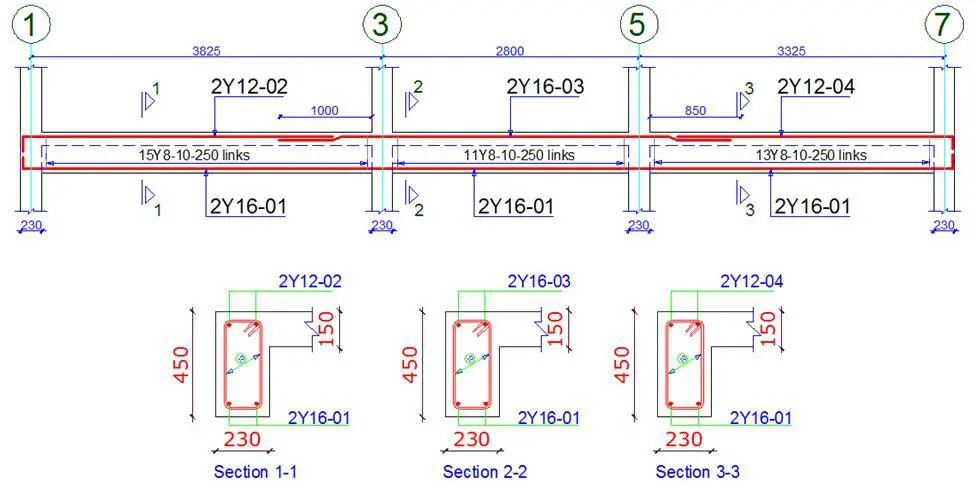
Reinforcement Detailing of Shear Walls
(a) Minimum and maximum area of vertical reinforcement
According to clause 9.6.2 of Eurocode 2, the minimum and maximum amounts of reinforcement required for a reinforced concrete wall are 0.002Ac and 0.04Ac outside lap locations respectively. It is further stated that where minimum reinforcement controls design, half of this area should be located on each face. The distance between two adjacent vertical bars should not exceed three times the wall thickness or 400 mm, whichever is lesser.

(b) Area of horizontal reinforcement
According to clause 9.6.3 of Eurocode 2, horizontal reinforcement should be provided at each face and should have a minimum area of 25% of the vertical reinforcement or 0.001Ac, whichever is greater. The spacing between two adjacent horizontal bars should not be greater than 400 mm.

(c) Provision of links
If the compression reinforcement in the wall exceeds 0.02Ac, links must be provided through the wall thickness in accordance with the rules for columns in clause 9.5.3 which are:

The diameter of the transverse reinforcement should not be less than 6 mm or one-quarter of the diameter of the largest longitudinal bar whichever is greater. The maximum spacing is to be Scl, max

Scl, max is the minimum of;

  • 20 times the diameter of the smallest longitudinal bar
  • The lesser dimension of the wall i.e. the thickness
  • 400 mm

The maximum spacing should be reduced by a factor of 0.6 in the following cases;

  • In sections within a distance equal to 4 × thickness of wall above or below a beam or slab.
  • Near lapped joints, if the diameter of the longitudinal bar is greater than 14 mm. A minimum of three bars evenly placed in the lap length is required.

Where the main reinforcement (i.e., vertical bars) is placed nearest to the wall faces, transverse reinforcement should be provided in the form of links with 4 per m2 of the wall area.

Design Example of Shear Walls

Design a 225 mm thick shear wall of 3.6 m height at the ground floor of the building. The shear wall is carrying a 200 mm thick slab on the first floor of the building. The action effects on the shear wall are as follows;

Vertical loads
Dead Load Gk = 300 kN/m
Live load Qk = 55 kN/m

Vertical load due to in-plane bending and wind Wk = ±650 kN/m
Vertical load due to in-plane bending and imperfections GkH = ±60 kN/m

Maximum moment out-of-plane, floor imposed load as leading action M = 40 kN/m @ ULS
Maximum moment out-of-plane, floor imposed load as accompanying action M = 35 kN/m @ ULS

fck = C25/30; fyk = 500 N/mm2

Check slenderness of wall at ground floor

Effective length, l0 = 0.75 × (3600 – 200) = 2550 mm (Table C16)
λ = 3.46 × l0/h = 3.46 × 2550/225 = 39.213 (Cl. 5.8.3.2(1))

Limiting slenderness, λlim = 20 ABC/n0.5 (Cl. 5.8.3.1(1))
where;
A = 0.7
B = 1.1
C = 1.7 – rm

where;
rm = M01/M02 = say = –0.25
C = 1.7 – (-0.25) = 1.95
n = NEd/Acfd

where;
NEd (assuming wind is the leading variable action) = 1.35Gk + 1.5Qk1 + 1.5Ψ0Qki
= 1.35(300 + 60) + 1.5(650) + (1.5 × 0.7 × 55) = 486 + 975 + 57.75 = 1518.75 kN/m
Acfd = (225 × 1000) × (0.85 × 30/1.5) = 3825 kN
Therefore, n = 1518.75/3825 = 0.397
λlim = 20 ×( 0.7 × 1.1 × 1.95)/0.3970.5 = 47.66

Therefore as λ < λlim wall is not slender and therefore no secondary moments.

Combinations of actions
(a) At ULS, for maximum axial load, Wk is leading variable action
NEd = 1.35Gk + 1.5Qk1 + 1.5Ψ0Qki
= 1.35(300 + 60) + 1.5(650) + (1.5 × 0.7 × 55) = 486 + 975 + 57.75 = 1518.75 kN/m

MEd = M + eiNEd ≥ e0NEd (Cl. 5.8.8.2(1), 6.1.4)

where
M = moment from 1st order analysis = 35 kNm/m
ei = l0/400 = 2550/400 = 6.375 mm (Cl. 5.2(7), 5.2(9))
e0 = h/30 ≥ 20 mm = 20 mm (Cl. 6.1.4)

MEd = 35 + (0.006375 × 1518.75) ≥ 0.020 × 1518.75
MEd = 35 + 9.68 ≥ 30.375 = 44.68 kNm/m

(b) At ULS, for minimum axial load, Wk is leading variable action
NEd = (1.0 × 300) – (1.35 × 60) – (1.5 × 650) + (0 × 55) = –756 kN/m (tension)

MEd = 35 + (0.006375 × 756) ≥ 0.020 × 756
= 35 + 4.82 ≥ 15.12 = 39.82 kNm/m

(c) At ULS, for maximum out of plane bending assuming Qk is leading variable action

NEd = 1.35(300 + 60) + (1.5 × 55) + (1.5 × 0.5 × 650) = 1056 kN/m

MEd = 40 + (0.006375 × 1056) ≥ 0.020 × 1056
MEd = 40 + 6.732 ≥ 21.12 = 46.732 kNm/m

or

NEd = (1.0 × 300) – (1.35 × 60) – (0 × 55) – (1.5 × 0.5 × 650) = -268.5 kN/m (tension)
MEd = 40 + (0.006375 × 268.5) = 41.71 kNm/m

Design load cases
Consolidate (c) into (a) and (b) to consider two load cases:

NEd = 1518.75 kN/m
MEd = 46.732 kNm/m (out of plane)

and

NEd = –756 kN/m (tension)
MEd = 46.732 kNm/m (out of plane)

Design: cover above ground
cnom = cmin + ∆cdev

where;
cmin = max[cmin,b; cmin,dur] (Exp. (4.1))

where
cmin,b = diameter of bar = 20 mm vertical or 10 mm lacers
cmin,dur = for XC1 = 15 mm
∆cdev = 10 mm
cnom = 15 + 10 = 25 mm to lacers (35 mm to vertical bars)

Design using charts
For compressive load:
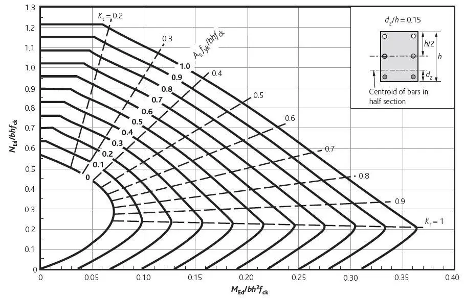
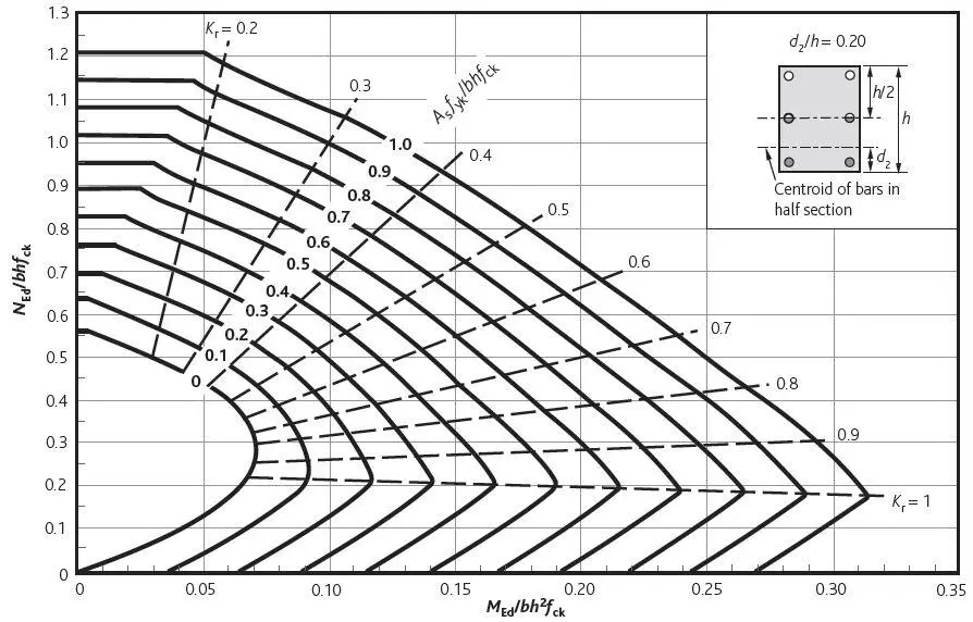
d2/h = (25 + 10 + 16/2)/225 = 0.19

Interpolate between charts for d2/h = 0.15 and d2/h = 0.2 as shown below

Column interaction chart
Rectangular column interaction chart for d2/h = 0.15
column intreaction chart 2
Rectangular column interaction chart for d2/h = 0.2


NEd/bhfck = (1518.75 × 103)/(225 × 1000 × 30) = 0.225
MEd/bh2fck = (46.732 × 10⁶)/(2252 × 1000 × 30) = 0.030

Gives:Asfyk/bhfck = 0
Therefore, minimum area of reinforcement required

As,min = 0.002Ac (Cl. 9.6.2 & NA)
As,min = 0.002 × 225 × 1000 = 450 mm2/m
As,min = 450 mm2/m = 225 mm2/m each face
maximum spacing = 400 mm c/c, minimum diameter of rebar = 12 mm diameter

Try H12 @ 300 c/c on each face

For tensile load and moment
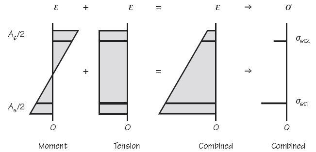
Working from first principles, referring to the figure below and ignoring contribution from concrete in tension,

stresses and strain in a shear wall subjected to bending and tension
Stresses and strains in wall subject to tension and out of plane moment


NEd = (σst1 + σst2) × As/2
and MEd = (σst1 – σst2) × As/2 × (d – d2)

So σst1 + σst2 = 2NEd/As
and σst1 – σst2 = 2MEd/[(d – d2)As]

st1 = 2NEd/As + 2MEd/[(d – d2)As]
As = (NEdst1) + MEd/(d – d2st1

σst1 = fyks = 500/1.15 = 434.8

As = (756 × 103/434.8) + (46.732 × 10⁶)/[(182 – 43) × 434.8] = 1738.7 + 773 = 2512 mm2

σst2 = 2NEd/As – σst1 = 601.9 – 434.8 = 167 MPa

By inspection all concrete is in tension zone and may be ignored.
Use 7H16 @ 175 c/c on both sides for at least 1 m each end of wall (Asprov = 2814 mm2).

Horizontal reinforcement
As,hmin = 0.001Ac or 25% As,vert (Cl. 9.6.3(1) & NA)
= 225 mm2 or (0.25 × 2814) = 704 mm2/m
This therefore requires 352 mm2/m each side
Use H10 @ 200 (393 mm2/m) both sides

Links
Check 0.02Ac = 0.02 × 225 × 1000 = 4500 mm2 > 2814 mm2
Therefore, links not required.
.


Technical Guide: Detailing and Arrangement of Beam Reinforcements on Site

Beams are horizontal structural elements used for supporting lateral loads. In conventional reinforced concrete structures, beams usually receive load from the floor slab, but may also be subjected to other loads such as wall load, finishes, services installation, etc. The design and detailing of reinforced concrete beams involves the selection of the proper beam size and the quantity of longitudinal and shear reinforcement that will satisfy ultimate and serviceability limit state requirements. Afterward, it is very important that the beam reinforcements are placed and arranged properly on site, to avoid construction error.

This article presents guides and short notes on how to properly place and arrange beam reinforcements on site. This is very important for students (on industrial training) or fresh graduates that are new to construction site practices.

Detailing and arrangement  of beam reinforcements
Typical detailing of a reinforced concrete beam

The technical guides to the detailing and arrangement of beam reinforcements are as follows;

(1) Confirm the formwork dimensions and stability
Beam reinforcement placement commences immediately after the carpenters complete the soffit formwork of the floor. At this point, it is important to verify that the formwork dimensions have been done according to the design specification. The checks should include measuring the beam width and the drop of the beam relative to the proposed surface of the slab. The sides of the beam drop should be checked for verticality to avoid having slanted beam sides, and the soffit should be checked for perfect horizontality. It is usually very difficult and depressing to make corrections after the reinforcement has been placed.

Poorly sized beam dimensions can also lead to compromised concrete cover, which can impact the bonding of concrete and reinforcement, the fire rating, and the durability of the building. It is typical to take a bent link (stirrup) and insert it in the beam drop to check if the desired concrete cover has been achieved. It can also be done to confirm that the beam size has been done according to specification. Furthermore, it is important to check the stability and bracing of the formwork to avoid collapse, bulging, or bursting.

(2) Confirm cut length and bending dimensions
Before the placement of the rebars commences, the site engineer should confirm that reinforcements have been cut and bent according to the design requirements. Bar bending schedule (BBS) can be used as a check document, provided it is very accurate and synchronised with what has been done on-site. All changes in dimensions or arrangements should be communicated ahead of time.

cut and bent reinforcement at a construction site awaiting installation
Cut and bent beam reinforcements at a construction site awaiting tying and placement

(3) Tying of Beam Reinforcements
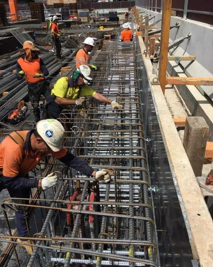
Links and stirrups are used for resisting shear stresses and torsion in a reinforced concrete beam. They are also used for holding the top and bottom reinforcement of beams in place. The correct quantity required should be installed and spaced as recommended in the structural drawing.

tying of beam reinforcement on site
Tying and arrangement of beam reinforcement on site

(4) Arrangement of Primary and Secondary Beams
For an internal beam (secondary beam), which is supported by another beam on either or both sides, the top bars should rest on the top bars of the primary beam. Also, the bottom bars should rest on the bottom bars of the primary beam as shown in the image below.

beam reinforement

(5) Arrangement of Beam-Column Junction at Corners
For beams occurring at a column junction at the corner of a building, either beam reinforcements can rest on each other.

corner beam column junction
Corner beam-column junction

(6) Arrangement of Continuous Beam-Column Junction
At a continuous beam-column junction as shown below, the continuous beam with heavier reinforcement will have to be placed on the beam with lighter reinforcement or the beam terminating at that point.

Internal beam column junction
Internal beam-column Junction

(7) Reinforcement Arrangement of Overhang (Cantilever) Beams
For cantilever beams, the main bars are the top reinforcements. If a side beam is resting on it (when the cantilever beam is acting as a primary beam) as shown in the image below, the top bars of the secondary beams beam must rest on the top bars of the cantilever beams. In the same vein, the bottoms bars of the side beam (main rebar) must rest on the bottom bars of the cantilever beam.

typical cantilever beam
Well designed and constructed cantilever beam

The arrangement of beams at a site should be checked strictly to conform to the engineer’s design drawings. Failure to check construction details properly may lead to the failure of the member or lack of robustness. We believe that beams are arguably the most common structural members in a building. Hence, attention should be given to its arrangements for robustness and efficient load transfer.

New Insights on the Failure of Fukae Bridge (Kobe 1995)

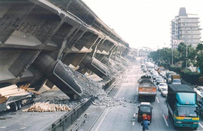
Researchers from the Department of Civil, Environmental, and Geomatic Engineering, ETH Zurich, Switzerland have offered new insights on the failure of Fukae Bridge during the Great Hanshin 1995 earthquake in Kobe, Japan. The magnitude 6.9 earthquake which left many damages behind its wake caused about $100 billion loss in properties, including the collapse of all 18 spans of the elevated Route No. 3 of Hanshin Expressway.

In the catastrophic seismic event, the deck of the bridge which was monolithically connected to 3.1m diameter piers failed and overturned dramatically. However, the massive 17–pile groups supporting the piers survived the earthquake and are still in use, supporting the new bridge. The piles were founded in alluvium sand and gravel formation.

seismicity of kobe
Figure 1: Japan, showing seismicity from 1961 to 1994, location of the 1995 Hanshin-Awaji
earthquake, and projected rupture areas of largest historical earthquakes to shake Kobe, which
were subduction-zone earthquakes in 1944 and 1946 (Source: https://www.geosociety.org/)

According to the authors, the lessons learned from the Kobe earthquake influenced substantially the seismic practices and codes not only in Japan but also worldwide. However, new insights have been offered on the failure of the bridge as the researchers carried out nonlinear finite element analysis of the bridge. The findings of the study were published in Elsevier -Soils and Foundations Journal.

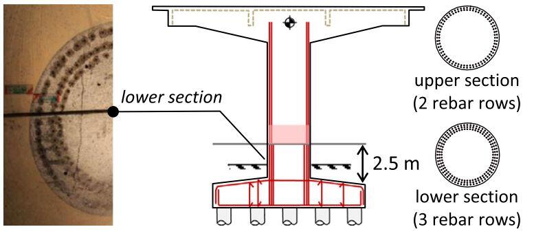
Previous studies attributed the failure of the bridge deck to inadequate structural design regarding mainly the addition of a prematurely terminated third row of longitudinal reinforcement and insufficient shear capacity due to poor transverse reinforcement. Surprisingly, the failure did not occur at the bottom of the pier (location of maximum bending moment) but 2.5 m above the pilecap, where shear cracking initiated.

bridge pier
Figure 2: Reinforcement details and critical section where the 3rd row of longitudinal rebars was terminated and shear cracking initiated; lower section of
a collapsed pier exposed in the Hanshin Expressway earthquake museum (Sakellariadis et al, 2020)

The authors, therefore, re-examined the collapse of the bridge by comparatively assessing the performance of the original foundation, which survived the earthquake and is still in use (for the fully replaced bridge), to that of alternative design concepts, considering nonlinear soil-foundation interaction.

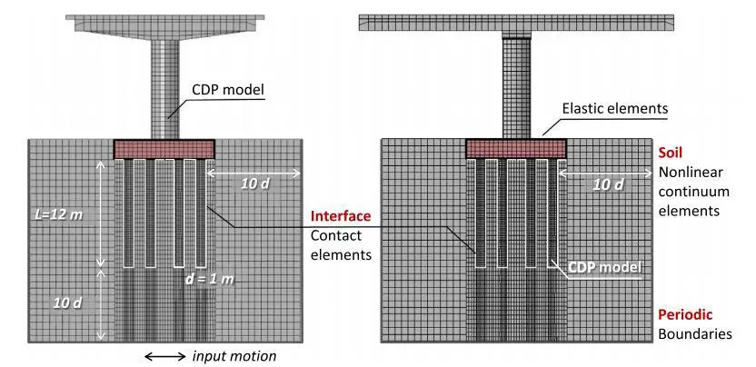
To achieve this, they carried out the static and dynamic response of a single segment of the Fukae bridge employing the FE method using ABAQUS software. Six different foundation configurations were explored, starting with the actual very stiff 17–pile foundation with its large cap and a highly nonlinear rocking shallow footing alternative consisting only of the pile cap. The soil profile was modelled with hexahedral (8-node) elements, adopting a thoroughly validated kinematic hardening model, with a modified pressure-dependent Von Mises failure criterion and associated plastic flow rule.

abaqus model
Key attributes of the FE model of a single segment of the Fukae bridge in Abaqus (Sakellariadis et al, 2020)

To gain deeper insights on the collapse mechanism, critical reinforced concrete (RC) structural members (pier and piles) were modelled and simulated with nonlinear solid elements, employing the Concrete Damaged Plasticity (CDP) model.

The numerical simulation successfully reproduced the shear-dominated failure mode at the longitudinal reinforcement cutoff region. The analysis also confirmed that, despite being highly overdesigned, the pile group foundation experienced limited but non-negligible swaying and rocking during shaking, as a result of which the piles were subjected to tension and combined shear-moment loading.

The resulting stiffness reduction of the cracked under tension piles leads to load redistribution towards the stiffer compressed piles, preventing plastic hinging of the weaker piles (under tension). These findings were found to be consistent with the post-earthquake in-situ testing.

Some of the conclusions inspired by the study are as follows;

  1. Reducing the number of pile rows in the critical direction of seismic loading is promising in improving the seismic performance, but not sufficient to prevent severe damage of the examined pier.
  2. The unconnected piled raft alternative reduces both the structural distress and the settlement.

References
L. Sakellariadis, I. Anastasopoulos and G. Gazetas, Fukae bridge collapse (Kobe 1995) revisited: New insights, Soils and Foundations, https://doi.org/10.1016/j.sandf.2020.09.005

Disclaimer
The original article cited above is an open-access article under the CC BY-NC-ND license (http://creativecommons.org/licenses/by-nc-nd/4.0/) which permits sharing, copying, and redistribution of the material in any medium or format provided appropriate credit is given. It has been presented on www.structville.com in form of a news article.


Structural Design Challenge | Explore your creativity

Building design concepts all over the world are evolving on a daily basis. Architects are coming up with different ways of making buildings appear sleeker, elegant, and more beautiful. While the aesthetic appeal offered by these contemporary buildings are commendable and decorate our environment, they can be a nightmare to structural engineers who have the responsibility of making the buildings safe and stable.

As a modern structural engineer, there is no good reason for not following up on the latest trends in design and construction. All the modern solutions available for analysis, design, and construction of complex-looking buildings should be handy to you. Furthermore, engineers should always follow up on the latest developments in construction materials and techniques by attending workshops, seminars, webinars, expos, conferences, etc that are relevant to their field of practice. That is one of the best ways of staying current and relevant in the industry.

A3

At Structville, we are interested in always driving up curiosity and creativity in the minds of civil engineers. It is not a good idea to ‘over-modify’ the concepts of an architect in the quest for structural stability. Therefore, you should not lack ideas on how to approach any problem that comes to you. That is the major sign of a quality engineer.

Ideas on how to support a complex architectural design may not always come immediately, but if you sleep and play over it, bearing in mind the ‘basic’ principles of statics of structures, and having a wide knowledge of different structural schemes, you will eventually find the solution. In practical design, you seldom need to think far or explore complex theories before you get an idea; the basic knowledge of statics of structures is usually sufficient.

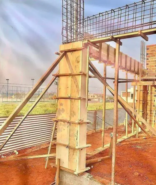
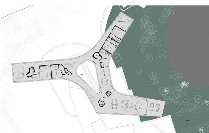
I came across an interesting architectural design on Instagram. No credit was given for the design, but the handle that posted the pictures is @academiadeestruturas. I am posting the pictures of the design below for us to explore our ingenious ways of carrying out the structural design of the building.

It is my hope that by the time a lot of professionals have contributed their ideas on how to go about the design, a lot of knowledge must have been passed around. For this structural design challenge, you can post your ideas as a comment or you can support with relevant sketches if necessary. The requirements of the challenge are as follows;

(1) Describe the structural scheme that you will use to support the building
(2) Describe the possible load path of the structural scheme
(3) Comment on the stability of the selected structural scheme
(4) State the most likely material that will work for the design

In a general, let us assume that the floor should be able to withstand a live load of 3.0 kN/m2. No calculations whatsoever are needed.

The pictures of the architectural design are given below;

A1
A2
A10
A3
A4
A5
A6
A8
A9

You are also free to comment or advise on the structural scheme selected by others. However, keep all interactions and use of language civil, professional, and respectful. Every engineering solution is a solution, but some solutions are better than the others. Remember to share this challenge with your friends and colleagues. Thank you, and God bless you.

Photo credit: Instagram@academiadeestruturas

Precast Lintels: A Cost and Time-Saving Solution in Construction

A lintel is a secondary structural member used to support a wall spanning above an opening in a masonry wall. They are usually categorised as elements of minor structural importance unless the span of the opening is very large. Lintels are usually horizontal members with a rectangular cross-section and are often made of reinforced concrete or steel. Other materials such as stone, brick, reinforced brick, and timber can also be used.

Lintels are important in a building, and the details can be included in the structural drawing in the form of lintel schedule to show the rebar specification based on the size of openings. Such a schedule can aid the quantity surveyor to capture the cost of the lintels in the bill of quantity.

In Nigeria, the most popular material used for lintel is reinforced concrete, which may be cast-in-situ or precast. Cast-in-situ lintels can be constructed to span around the entire length of walls in the building, and are often referred to chained lintels. On the other hand, they can be constructed to span across the opening concerned without extending far beyond the opening. Precast lintels are often used to span across the opening concerned only.

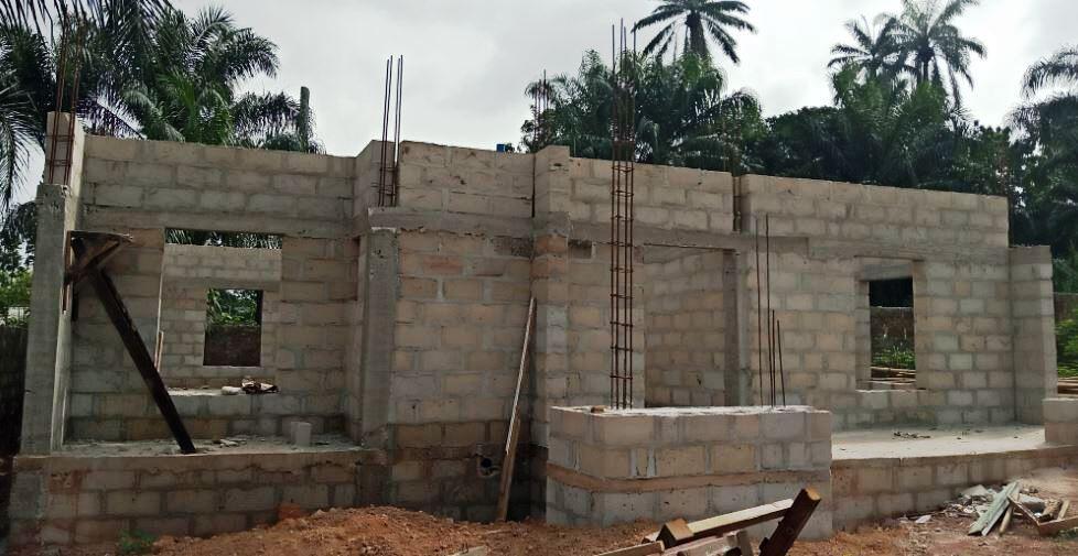
Building with chained lintel
Chaining of lintels in a building

Precast lintels always come in handy for residential buildings and are mostly employed by value engineers. The major benefits include cost and time saving for the project or contractor.

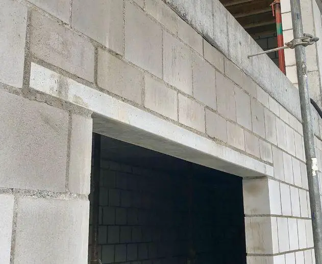
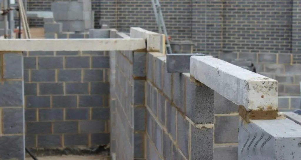
Precast lintels installed in a build
Precast concrete lintel

Essentially, the idea behind thin precast lintels is that the provision of top reinforcements and hanger bars can be neglected for lightly loaded one-span members in bending. Reinforcements are provided at the bottom of the lintel to take up all the flexural stresses. The conventional cast-in-situ lintel, however, has an edge over precast lintel if the building will be subjected to remodeling or if the lintels spans between reinforced concrete columns.

Advantages of Precast Lintels

The advantages of using precast lintels in construction are as follows;

  1. Significant saving in reinforcement is obtained by using offcuts from other elements
  2. It more sustainable because of the reduction in cement and aggregates requirements
  3. Quality control in the production of the lintel is enhanced
  4. It also saves and/or reduces the cost of formwork
  5. It reduces the cost of labour
  6. It is relatively easy to construct
  7. Saves time on the construction program since it can be produced and stored ahead of schedule.

Disadvantages of Precast Lintels

  1. A lifting mechanism may be required to put the lintel in place
  2. The robustness of the wall/element is reduced
  3. The bond strength of the wall and the lintel is weaker when compared with cast-in-situ

Specifications for Precast Lintels

(1) Sizing: The width of a lintel should be equal to the width of the wall they are supporting or sitting on, unless otherwise specified. The depth of a lintel should be a minimum of 100 mm, and the length depends on the span of opening. An end bearing length of at least 200 mm beyond the face of the opening should be provided. When the span of a lintel exceeds 2m, a more serious consideration should be given.

(2) Concrete: A minimum concrete grade of 15 MPa should be used for the construction of lintels, unless otherwise specified. The quality of the cement, aggregate, and water should be the minimum requirement used for the construction of major reinforced concrete elements.

(3) Reinforcements: A 2 or 3 number of high yield 12mm diameter bars (2Y12 or 3Y12) placed at the bottom of the lintel is usually sufficient. However, the minimum area of reinforcement required for the section provided should not be violated (0.13% of the cross-sectional area). Top reinforcements (hanger bars) with links (stirrups) may or may not be provided depending on the depth adopted. When links are provided, the minimum area and spacing required should be provided.

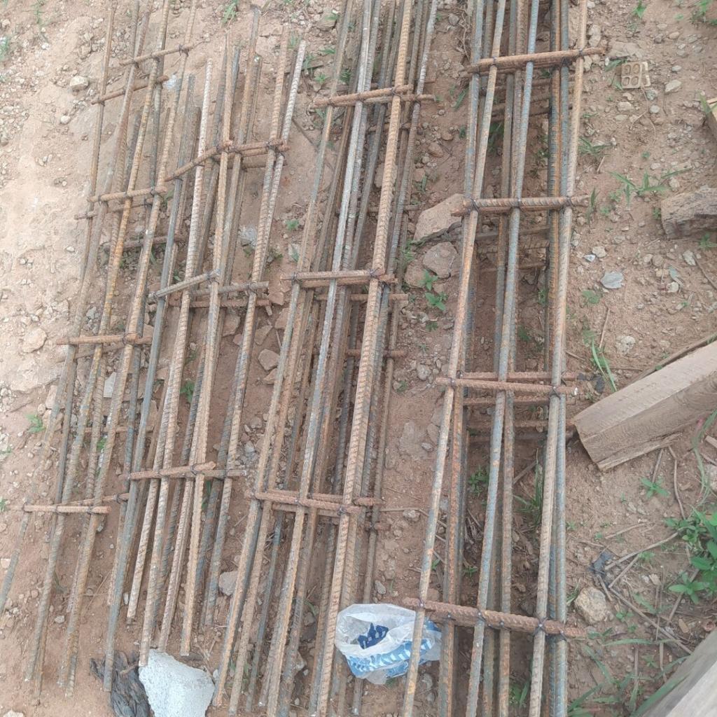
IMG 20201111 212104
Typical reinforcement cutting and fixing for a precast lintel

Technical Guide for Construction of a Precast Lintel

(1) Surface preparation: A flat surface is required for casting of a precast lintel. This can be achieved on a well-leveled floor or on a marine plywood placed on a hard surface. The marine board will cover all undulations that may come from the surface, and will give a smooth finished appearance.

(2) Ease of removal: A cement sack or membrane should be spread on the surface to receive the lintel concrete, and to aid in quick removal without sticking with the platform. Alternatively, the surface of the marine board can oiled using an approved material.

(3) Shuttering/Mould Construction: The mould for the precast concrete can be achieved using planks or marine boards joined together. Special moulds made of steel or plastic can also be used where available.

(4) Concrete cover: Provision of nominal concrete cover (to the links) not less than 15mm should be made. Normally, fire rating, bond, and durability (exposure conditions) of the lintel should inform the choice of concrete cover.

(5) Concreting: A concrete mix of strength not less than 15 MPa after 28 days should be carefully poured and consolidated in the form/shuttering prepared. A vibrator is usually not needed for precast lintels as consolidation can be achieved by tamping the concrete or tapping the sides of the form/shuttering. The top surface can be finished using a trowel.

(6) Curing: Remove the forms after 24 hours and cure using any suitable method for at least 7 days before placement.

(7) Handling and Storage: Precast concrete lintels are fragile elements that can get damaged when not properly handled. All forms of impact or dropping from height should be avoided. The elements should be stored on a flat surface and protected until they are due for placement.

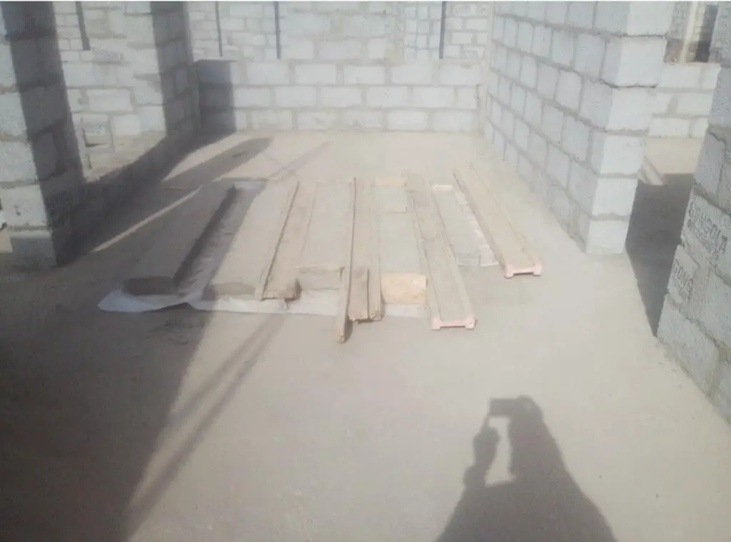
IMG 20201111 212333
Arrangement of temporary forms on a flat surface for precast lintel
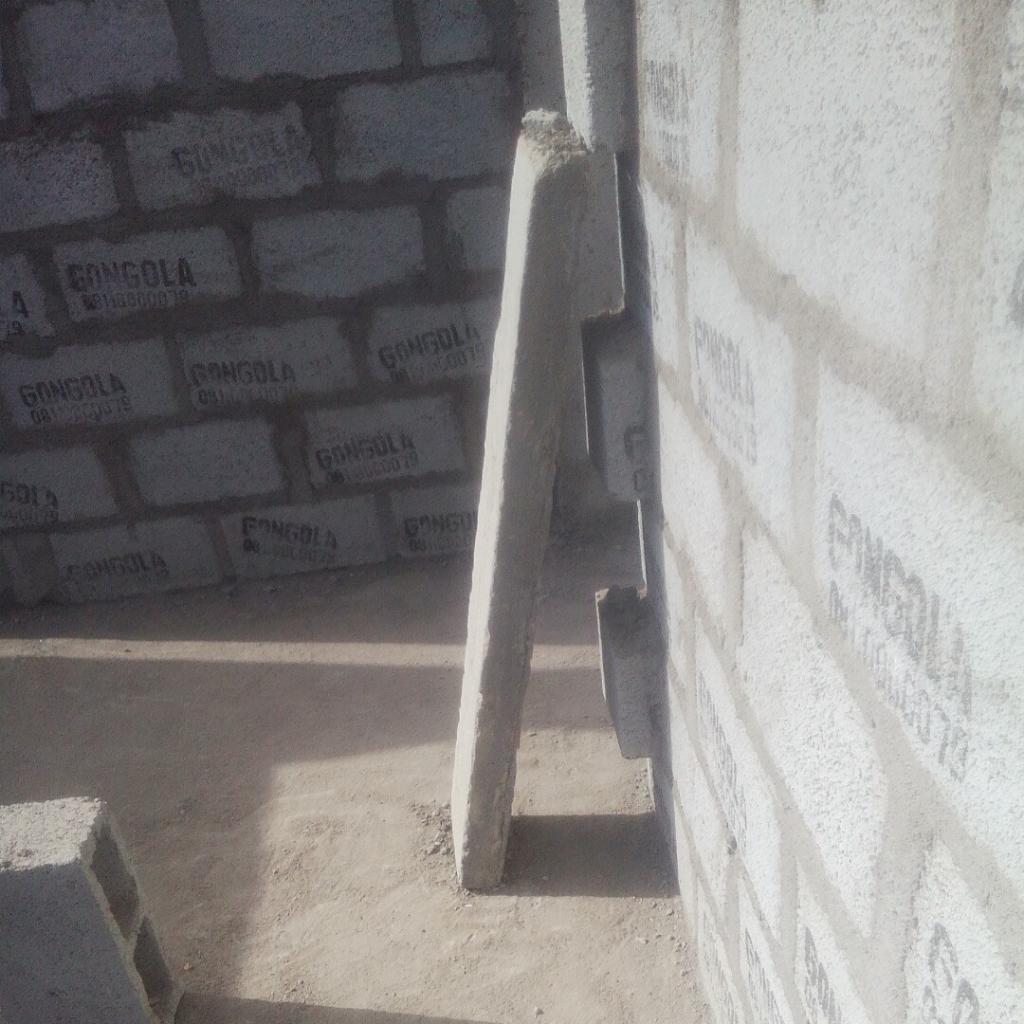
IMG 20201111 212132 1
A unit of precast lintel of 100mm x 230mm x 1300mm

Placement/Installation of Precast Lintels

  1. Place high-quality cement mortar around the end bearing of the masonry wall that will support the lintel
  2. Lift the precast lintel carefully and place it on the mortar taking note of alignment and level
  3. Apply temporary support to transfer the stresses efficiently.

Recommendation

  1. Architects should make an allowance of using precast lintels in their designs by making window or door opening spans on masonry walls. Though this may not always be feasible due to the presence of columns in important areas.
  2. Low-cost and mass housing schemes can employ precast lintels to save cost and improve on delivery time.
  3. Value Engineers, Contractors, and Consultants should adopt precast lintels in their constructions.

Conclusion

The use of precast lintel is a cost and time-saving alternative in construction. It is also a sustainable practice that can lead to the reuse of waste materials on-site like empty cement bag, old planks/formworks, reinforcement offcuts, and waste concrete materials.

PS: At Structville, we value sustainability and value engineering. Do you want a review and analysis of your drawings and bills to see where you can save cost and time without sacrificing quality? You can reach us at info@structville.com to have a deal with our team of value engineers.

Elastic Analysis of Circular Plates

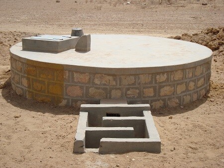
A plate is a flat structural element that has a thickness that is small compared with the lateral dimensions. Plates are bounded by two parallel planes, called faces, and a cylindrical surface called an edge or boundary. The thickness is usually constant but may be variable and is measured normal to the middle surface of the plate. Circular plates are common in many structures such as nozzle covers, end closures in pressure vessels, pump diaphragms, turbine disks, and bulkheads in submarines and airplanes, etc. They are also used as bases or covers of cylindrical water tanks and structures. When they are resting on the ground, they behave as plates on an elastic foundation.

circular concrete plate
Typical circular plate covering an undergound tank

In the elastic analysis of circular plates, it is convenient to express the governing differential equation in polar coordinates, even though rectangular (Cartesian) coordinates can be used (as applied in this article). This can be readily accomplished by a coordinate transformation and can be found in many pieces of literature.

If the coordinate transformation technique is used, the following geometrical relations between the Cartesian and polar coordinates are applicable;

elastic analysis of circular plate

x = a cosθ; y = a sinθ; x2 + y2 = a2 —- (1)
θ = tan-1(y/x)

Referring to the above;
∂r/∂x = x/r = cosθ; ∂r/∂y = y/r = sinθ
θ/∂x = -y/r2 = -sinθ/r; θ/∂y = x/r2 = cosθ/r

The governing differential equation (biharmonic equation) for the elastic deflection of a plate in polar coordinates is given by equation (2);

r4w = (∂2/∂r2 + ∂/r∂r + ∂2/r2∂θ2)(∂2w/∂r2 + ∂w/r∂r + ∂2w/r2∂θ2) = q/D — (2)

This is equivalent to the moment-curvature relationship of a thin plate which is given by (3);

4w/∂x4 + 24w/∂x2∂y2 + ∂4w/∂y4 = q/D — (3)

Where D is the flexural rigidity of the plate which is given by;
D = Eh3/12(1 – ν2) — (4)

h = thickness of the plate
E = Modulus of elasticity of the plate material
ν = Poisson ratio of the plate material

Circular Plate Clamped at the Edge and Subjected to Uniform Load

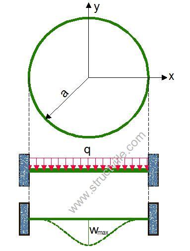
CLAMPED CIRCULAR CARRYING UNIFORM LOAD

Let us consider a circular plate clamped at all edges (fixed) and subjected to a uniform lateral load q. The boundary of the plate is given by y2 + x2 = a2

For a such a clamped circular plate, the slope and deflection at the edges are zero;
w = 0; ∂w/∂x = 0; ∂w/∂y = 0 along y2 + x2 = a2

The solution to the deflection equation of the plate is given by;

w = c(x2 + y2 – a2)2 which satisfies the condition given above.

Let f(x, y) = x2 + y2 – a2
The partial derivatives are given by;

∂w/∂x = 4cxf; ∂w/∂y = 4cyf
2w/∂x2 = 4c(2x2 + f); 2w/∂x∂y = 8cxy; 2w/∂y2 = 4c(2y2 + f)
3w/∂x3 = 24cx; 3w/∂x2∂y = 8cy; 3w/∂x∂y2 = 8cx; 3w/∂y3 = 24cy
4w/∂x4 = 24c; 4w/∂x2∂y2 = 8c; 4w/∂y4 = 24c

Substituting this into the biharmonic equation, we can verify that;

c = -q/64D

Hence the elastic deflection of a circular plate clamped at all edges and subjected to a uniform lateral load is given by;

w = -q/64D(x2 + y2 – a2)2

The maximum deflection occurs at the centre of the plate and it is therefore given by;

wmax = -qa4/64D

The moments occurring in the plate from the moment-curvature equations are;

Mx = -q/16[(3 + v)x2 + (3v + 1)y2 – (1 + v)a2]
My = -q/16[(3v + 1)x2 + (3 + v)y2 – (1 + v)a2]
Mxy = q/8(1 – v)xy

The out-of-plane shear forces can be given by;

Vx = -qx/2; Vy = -qy/2

At the centre of the plate;

Mmax = q/16 × (1 + v)a2; Vx = Vy = Mxy = 0
The maximum moment occurs at the edge of the plate and it is given by Mr = -qa2/8

Simply supported circular plate subjected to a uniform lateral load

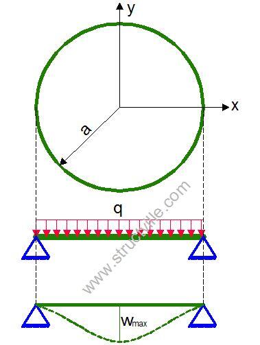
SIMPLY SUPPORTED CIRCULAR PLATE CARRYING UDL

The boundary conditions are at the support, the deflection is zero, and the bending moment is zero.
w = 0; Mx = My = 0

The equation of the deflected surface is given by;

w = C3r2 + C4 + qr2/64D

The expression for the bending moment Mr can be given as;

Mr = -D[2C3(1 + v)+ qr2/16D × (3 + v)]

Introducing the equations for bending moment and deflection into the boundary conditions;

C3 = -qa2(3 + v)/32D(1 + v); C4 = qa4(5 + v)/64D(1 + v)

Therefore, the elastic deflection of a circular plate simply supported at the edges is given by;

w = [-q(a2 – r2)/64D × ((5 + v)/(1 + v) × (a2 – r2))]

The maximum deflection which occurs at x = y = 0 is therefore;

wmax = qa4/64D × (5 + v)/(1 + v)

The bending moments are as follows;

Mr = q/16(3 + v)(a2 – r2)
Mt = q/16[(3 + v)a2 – (1 + 3v)r2]
Note: r2 = x2 + y2

The maximum moment occurs at the centre of the plate (r = 0), and it is given by;

Mmax = qa2/16 × (3 + v)

Clamped circular plate with a concentrated force at the center

CLAMPED CIRCULAR CARRYING CONCENTRATED LOAD

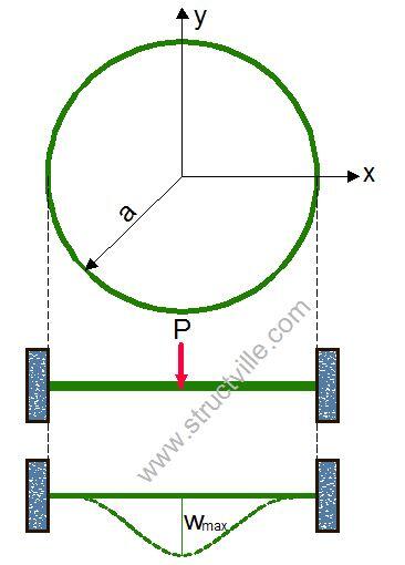
Clamped circular plate with a concentrated force P at the center, the expression for the deflection is given by;

w = P/16πD× (2r2In(r/a) + a2 – r2)

The bending moments are given by;

Mr = P/4π [(1 + v)In(a/r) – 1]
Mt = P/4π [(1 + v)In(a/r) – v]

Simply supported circular plate with a concentrated force at the center

Simply supported circular plate with a concentrated force at the center

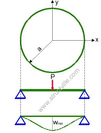
For a simply supported circular plate with a concentrated force P at the center, the expression for the deflection and bending moments are given by;

w = P/16πD× (2r2In(r/a) + (3 + v)/(1 + v) × a2 – r2)
Mr = P/4π [(1 + v)In(a/r)]
Mt = P/4π [(1 + v)In(a/r) + 1 – v]

Solved Examples on the Analysis of Circular Plates

A circular plate of thickness (150 mm) and diameter 10m is subjected to a uniform lateral load of 10 kN/m2. Calculate the deflection and bending moment at the centre of the plate assuming;
(a) Simply supported conditions
(b) Clamped edge conditions
(v = 0.2; E = 2.1 x 10⁷ kN/m2)

Solution
The flexural rigidity of the plate is given by;
D = Eh3/12(1 – ν2) = (2.1 × 107 × 0.153)/12(1 – 0.22) = 6152.34 kNm

(a) Assuming simply supported edge
(i) Maximum deflection
wmax = qa4/64D × (5 + v)/(1 + v) = (-10 × 54)/(64 × 6152.34) × (5 + 0.2)/(1 + 0.2) = 0.06877 m = 68.78 mm

(ii) Maximum bending moment
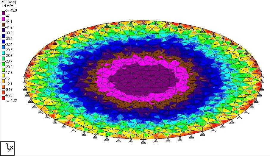
Mmax = qa2/16 × (3 + v) =(-10 × 52)/16 × (3 + 0.2) = 50 kNm

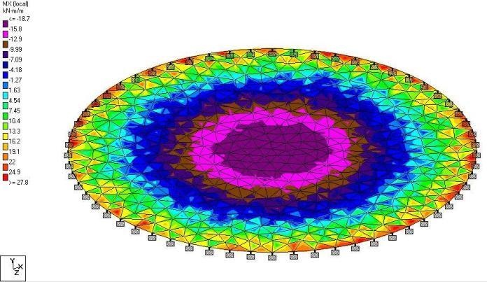
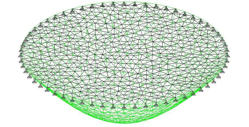
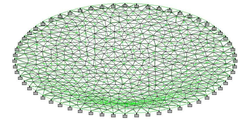
When analysed using finite element analysis on Staad Pro;

deflected profile of circular plate

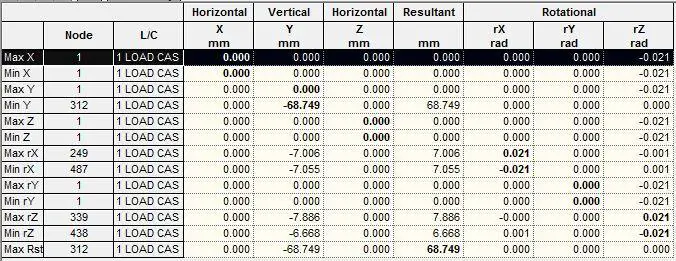
The maximum deflection at the centre of the plate was observed to be 68.749 mm as shown in the table below. This comparable with 68.78 mm obtained using classical theory.

finite element analysis result

The bending moment obtained using finite element analysis was observed to be 49.9 kNm/m as shown below. A value of 50 kNm was obtained using classical theory.

bending moment on circular plate


(b) Assuming clamped edge conditions;
(i) Maximum deflection
wmax = -qa4/64D = (-10 × 54)/(64 × 6152.34) = 0.0158 m = 15.87 mm

(ii) Bending moment at the center
Mmax = q/16 × (1 + v)a2 = 10/16 × (1 + 0.2) × 52 = 18.75 kNm

(iii) Bending moment at the edge
Mr = -qa2/8 = (-10 x 52)/8 = -31.25 kNm


When analysed on Staad Pro;

deflected profile of a clamped circular plate 1


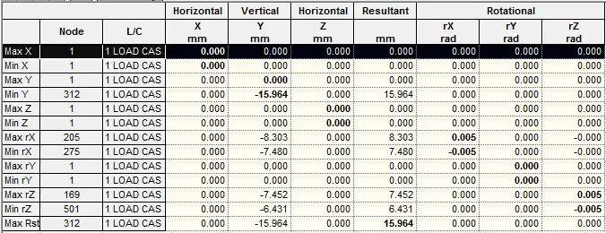
The maximum deflection at the centre of the plate was observed to be 15.964 mm (compared with the value of 15.87 mm obtained using classical theory)

finite element analysis of result of a clamped circular plate

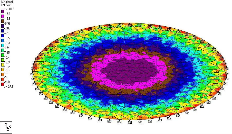
The bending moment values from the finite element analysis result are shown below;

bending moment of a clamped circular plate

Summary of Analysis Result

Type of plate/Action EffectStaad Pro (FEA)Classical MethodPercentage Difference
Simply supported
Deflection (mm)

68.75 mm

68.78 mm

-0.0436%
Span Moment (kNm)49.9 kNm50 kNm-0.2%
Clamped Plate
Deflection (mm)

15.964 mm

15.87 mm

0.563%
Span Moment (kNm)
Edge Moment (kNm)
18.71 kNm
-27.8 kNm
18.75 kNm
-31.25 kNm
-0.213%
-12.41%

Bar Bending Schedule: Preparation, Applications, and Standards

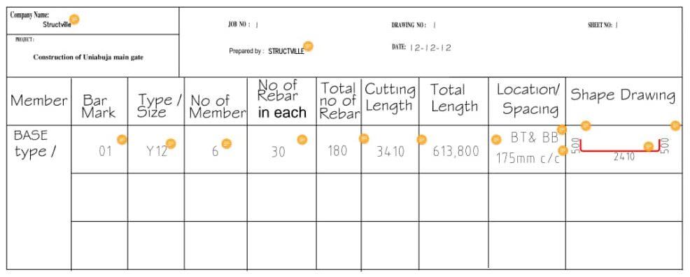
On a construction site, there are different quality control/quality assurance systems to ensure the efficient delivery of a project. One of these is the Bar Bending Schedule (BBS). A bar bending schedule is a document showing the list of structural members, bar mark, type of reinforcement, size of rebar, number of rebars for each member, cutting length, total length, shape, and location/spacing/position of all reinforcements in the working drawing.

Bar bending schedule ensures that reinforcement cutting, bending, and placement are carried out in the most efficient manner on site. It also guides against the excessive waste of reinforcement by minimising the number of useless offcuts. The document is prepared in a manner such that the reinforcement requirements and specification can be recognised and applied without confusion on site. It is issued for different structural elements such as reinforced concrete beams, columns, slabs, foundation, staircase, etc.

Typical bar bending schedule

In Nigeria, the table showing lists of standard shape codes given in BS8666 doesn’t necessarily conform to the style used in Nigerian construction sites. Some modifications are usually done to avoid confusion, mistakes, and to reduce the workload/effort of the fitters (iron benders). It is very typical for detailers to sketch the actual bending shape on the document instead of referring to the standard shape code.

Read Also…
Preparation of bar bending schedule for slabs
Structural design and detailing standards in Nigeria

The importance of bar bending schedule on a construction site cannot be overemphasized. Some of these includes:

  1. To serve as a control document for Clerk of work, Inspectors, Detailers, and Structural Engineers on reinforcement
  2. For quantification of materials by the quantity surveyor during pre-contract and post-contract operations
  3. To assist steel bender and fixer
  4. To fast track construction and supervision;
  5. To plan, detect inconsistencies, and save costs in the handling of reinforcements.

Preparation of Bar Bending Schedule

Preparation of bar bending schedule should not be a haphazard operation. It should begin with the appropriate study of the reinforcement detailing drawings. All inconsistencies or errors (such as repeated bar marks for different types of bars) discovered in the drawing should be reported to the detailer, because as practically as possible, the details of the structural drawing and the bar bending schedule should be synchronised.

The major check lists before the commencement of BBS includes but not limited to the following:

  1. Check the concrete cover to each face
  2. Check the lapping length for tensions and compression bars of each structural elements
  3. Check the direction of bend of each bar
  4. Group each structural unit and floor by floor. For example, all ground floor elements must be scheduled before proceeding to next floor and all footing must finish before proceeding to starter columns.
  5. Bar mark must start from 01 and increasing upward consecutively
  6. Good knowledge of detailing, and considerations affecting the practical construction.

Notations in reinforcement detailing

It is also very important to be familiar with the style used by the draughtsman and its corresponding meaning in the standard detailing practice. For example, in the detailing of a floor slab, the standard method and the corresponding preferred style in Nigeria is as follows:
British Standard
Bottom (face): B1 (outer layer) and B2(second layer)
Top (face): T1 (outer layer) and T2 (second layer)

Nigerian style
B1 = Bottom Bottom (BB) or Bottom (B)
B2 = Bottom Top (BT) or Near Bottom (N)
T1 = Top Top (TT) or Top (T)
T2 =Top Bottom (TB) or Near Top (NT)

It is however common for the notation used in the structural detailing to be given in the design notes.

SLAB%2BDET%2B2
SECTION

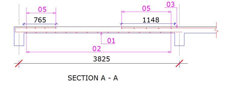
For example, a main bar of a slab is typically detailed as 12H12-01-250B1 according to standard. However, the common notation used in Nigeria is 12Y12-01-250 BB, which means 12 numbers of high yield deformed bars of 12mm nominal size, at a spacing of 250mm center to center, in the bottom-bottom layer. The bar mark is -01- (Note: BB is the same thing as bottom outer layer). There might not be so much difference in notation based on what is seen above, but it is very important for the detailer to familiarise himself with the loacal standards.

Sections of a Bar Bending Schedule

A typical BBS contains the heading and the schedule section. The heading usually contains information which includes the following:

COMPANY NAME: Provide the name of the company issuing the schedule e.g. Structville Integrated Services Ltd.
PROJECT: Provide the title of the project. E.g. Construction of UniAbuja Main Gate
JOB NO: This is the number assigned to the job by the company or the client.
PREPARED BY: This shows the person that prepared the schedule
DRAWING NO: This gives the particular page in the drawing which references the schedule
DATE: This shows the date the schedule was prepared with reference to any revised schedule
SHEET NO: This shows the page by page documentation/compilation of the schedule

The presentation style of the schedule section of a BBS varies. Different companies always present their schedule in a way that suits them and their workers. Some schedules include the length and number of offcuts expected from a standard length of reinforcement or structural element to guide them in the reuse of reinforcements. For instance, two variants of schedules are shown in the images below.

BBS 1
Bar%2BBending%2BSchedule%2BTable

However, a typical BBS schedule section contains 10 columns in the following order:

[1] MEMBER: This shows the particular member in consideration. E.g base type 1, base type 2, column type 1, column type 2 etc

[2] BAR MARK: This depicts different bar marks present in the drawing. E.g. 01, 02, 03 etc.

[3] TYPE and SIZE: Type relates to whether the specified reinforcement is of high or mild yield, while size depicts the diameter of the bar and typically includes 8, 10, 12, 16, 20, 25, 32, and 40mm bars.

[4] NO. OF MEMBER: This shows the number of times the particular structural elements occur. E.g In the foundation details, how many numbers of Base Type 1 are there?

[5] NO. OF REBAR IN EACH: This means the number of times that particular bar marks occur in that particular member.

[6] TOTAL NO. OF REBAR: This column is the multiplication of columns [5] and [6] to show the cumulative of that particular bar mark.

[7] CUT LENGTH: This column comes next after the previous column. However, in preparing the schedule, the column showing the rebar “shape drawing” has to be done first in order to arrive at the cutting length.

[8] TOTAL LENGTH: This column is the multiplication of columns [6] and [7] to give the overall length of a particular bar mark of a particular element in the entire drawing. The total length is what is used by a Quantity Surveyor to quantify and price. From there, each length or tonnage is gotten as an executive summary. It is also important for data to know how many labourers or man-hours that will be expended on the work.

[9] LOCATION OR POSITION OR SPACING: This is the 9th column on the schedule. Here, if it is a wall, slab or foundation, the layers, and spacing of the bar are shown. If it is a link (stirrup), the spacing is shown and if it is a beam, the position is shown. It is important information for steel fixers.

[10] SHAPE DRAWING: This is the 10th and final column on the schedule. It shows the drawing and the dimensions of all the bends, straights, and the direction each bar is assumed to face after placement. This approach is more detailed and straightforward compared to the main standard where you need a separate sheet of shape code list and separate columns for each dimensions.

For a contractor that uses a fast-track approach, this column is of utmost importance to prefabricate all the shapes and fix all elements ready for placement. E.g all the columns in a story building can be done immediately after mobilization to site. This saves time on the construction program.

Conclusion

The main standard has been domesticated and adapted to be peculiar to the design and construction industry in Nigeria. The Nigerian standard style conforms to BS8666:2005. It is satisfactory and praiseworthy to say that the Nigerian style is comprehensive and easy to understand by a layman. We believe that complex English, Mathematics, Schedule, or Drawing should not be used to confuse sense of good engineering.

Shear Wall-Frame Interaction in High-Rise Buildings

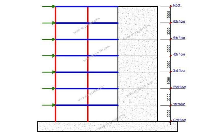
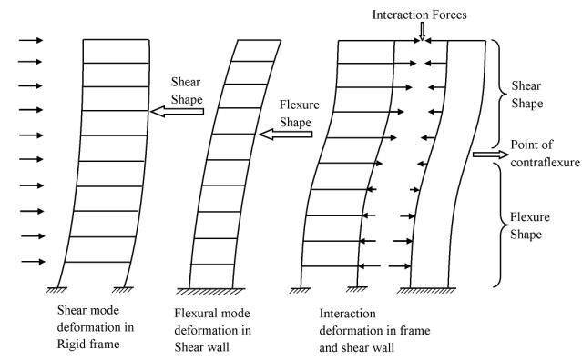
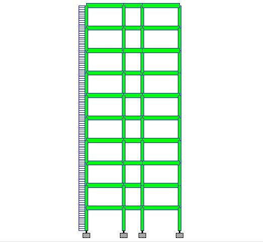
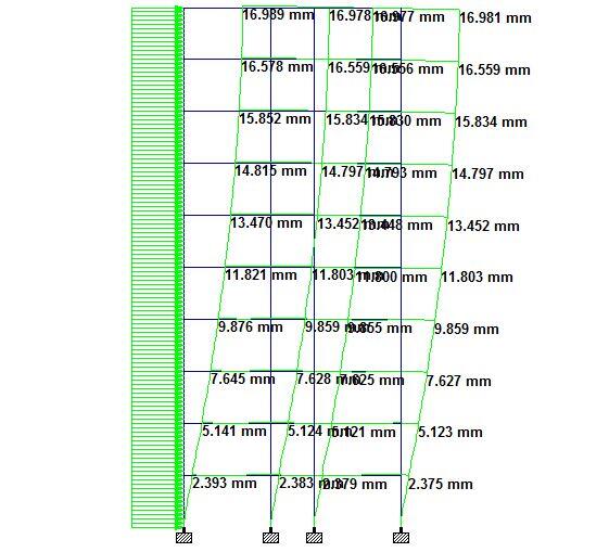
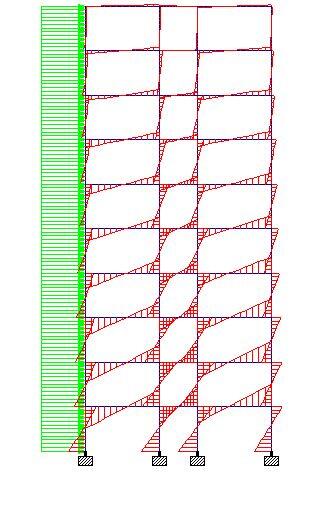
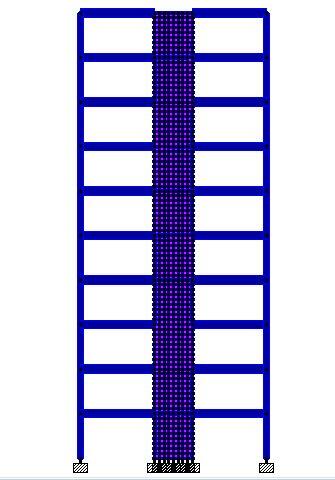
Shear walls and frames (comprising of columns and beams) are distinct structural systems that can be used in resisting lateral actions in high-rise buildings. However, as a building goes higher, frames alone become inadequate for lateral stability, hence, the structure can be augmented by shear walls and/or cores. Shear wall-frame interaction for lateral load resistance is complex because shear walls deflect primarily in bending mode, while frames deflect in shear mode.

However, the interaction between shear walls and frames is beneficial for high-rise buildings, since the linkage and stiffness of the floor slab diaphragm and the stabilising elements give better lateral load resistance. Furthermore, since their mode of deflection varies, the frame tends to restrain the shear wall in upper storeys and the shear wall tends to restrain the frame in the lower storeys. This reduces the lateral deflection and improves the overall efficiency of the structural system.

Shear Wall-Frame Interaction in High-Rise Buildings
Frame-shear wall interaction

Shear walls are stiffer than columns, hence they take up most of the lateral load. This has sometimes led to the conservative approach of transferring the entire lateral load to the shear walls during design. When the building is very tall, the flexural deformation of the shear wall becomes very pronounced and hence, must be allowed for in the analysis. Shear wall-frame systems have been used successfully in buildings ranging from 10 storeys to 50 storeys.

The difference in behavior under lateral load, in combination with the in-plane rigidity of the floor slabs, causes nonuniform interacting forces to develop when walls and frames are present. This makes the analysis more difficult. If torsion is not considered in the analysis, two simplified manual methods of determining the interaction of frames and shear walls are:

  • Use of charts given by Khan and Sbarounis (1964) or PCA’S Advanced Engineering Bulletin No. 14, f7), and
  • Use of Equation (C) by PCA.

In order to use these charts, the structure must be reduced to a single frame and a single wall by the addition of the properties of the separate vertical units. In both references, the stiffnesses (Iw) of all the shear walls are summed to give an equivalent single wall.

In this article, we are going to investigate the effects of shear wall-frame interaction in the resistance of uniformly distributed lateral loads using finite element analysis. A 2D model of a 10-storey and 50-storey building will be used in the analysis.

Model 1A: Analysis of a 10-storey Frame Without Shear Wall

Height of building = 30 m
Inter-storey height of building = 3 m
Dimension of beams = 400 x 600 mm
Dimension of columns = 400 x 400 mm
Lateral load = 5 kN/m

10 STOREY FRAME
Model of a 10 storey frame

When analysed on Staad Pro software, the analysis results are as follows;

DELECTED SHAPE OF 10 STOREY BUILDING
Lateral deflection of a 10 storey frame
Bending moment diagram of a tall building 1
Bending moment diagram of the 10 storey frame

Summarily, the analysis result of the 10-storey frame without shear walls is as follows;

Deflection
Maximum deflection at roof level = 16.989 mm
Deflection at 1st floor = 2.393 mm

External Column (windward side)
Bending moment = 59.1 kNm
Shear force = 39 kN
Axial force = 146 kN

Internal Column (windward side)
Bending moment = 63.5 kNm
Shear force = 39.9 kN
Axial force = 72.8 kN

First-floor beams
Bending moment = 75 kNm
Shear force = 26.4 kN
Axial force = 7.68 kN

Model 1B: Analysis of a 10-storey frame with shear wall

Height of building = 30 m
Inter-storey height of building = 3 m
Dimension of beams = 400 x 600 mm
Dimension of columns = 400 x 400 mm
Length of shear wall = 2500 mm
Thickness of shear wall = 250 mm
Lateral load = 5 kN/m

SHEAR WALL FRAME INTERACTION
Model of a 10 storey frame with shear wall


Deflection
Maximum deflection at roof level = 7.120 mm
Deflection at 1st floor = 0.319 mm

V1
Lateral deflection of a shear wall-frame model

External Column (windward side)
Bending moment = 13 kNm
Shear force = 12.7 kN
Axial force = 105 kN

First-floor beams
Bending moment = 20.8 kNm
Shear force = 8.08 kN
Axial force = 18.9 kN

MAX ABSOLUTE
Maximum absolute stress on the shear wall

Shear Walls
Maximum absolute stress = 1913.65 kN/m2
Sx = 1884.42 kN/m2
Sy = 508 kN/m2

SHEAR WALL 55
Axial stress on the shear wall

Model 2A: Analysis of a 50-storey building without shear wall

Height of building = 150 m
Inter-storey height of building = 3 m
Dimension of beams = 400 x 600 mm
Dimension of columns = 400 x 400 mm
Lateral load = 5 kN/m

Summary of analysis results

Deflection
Maximum deflection at roof level = 1516.839 mm
Deflection at 1st floor = 13.739 mm

External Column (windward side)
Bending moment = 299 kNm
Shear force = 171 kN
Axial force = 4170 kN

Internal Column (windward side)
Bending moment = 340 kNm
Shear force = 208 kN
Axial force = 1142 kN

First-floor beams
Bending moment = 411 kNm
Shear force = 145 kN
Axial force = 7.94 kN

Read Also…
Aspects of shear wall modelling
Application of wind load to shear walls

Model 2B: Analysis of a 50-storey framed building with shear wall

Height of building = 150 m
Inter-storey height of building = 3 m
Dimension of beams = 400 x 600 mm
Dimension of columns = 400 x 400 mm
Length of shear wall = 2500 mm
Thickness of shear wall = 250 mm
Lateral load = 5 kN/m

Deflection
Maximum deflection at roof level = 1297.128 mm
Deflection at 1st floor = 2.522mm

External Column (windward side)
Bending moment = 66.5 kNm
Shear force = 38.6 kN
Axial force = 3887 kN

First-floor beams
Bending moment = 137 kNm
Shear force = 53.3 kN
Axial force = 46.5 kN

Shear Walls
Maximum absolute stress = 15734 kN/m2
Sx = 15604.6 kN/m2
Sy = 4547.11 kN/m2

Discussion of results

Model 1

Element (Action Effect)Without shear wallWith shear wallPercentage Difference (%)
Maximum deflection 16.989 mm7.120 mm58.09 %
Deflection at first storey2.393 mm0.319 mm86.67 %
Column bending moment59.1 kNm13 kNm78%
Column shear force39 kN12.7 kN67.43%
Column axial force146 kN105 kN28.08%
Beam bending moment75 kNm20.8 kNm72.26%
Beam shear force26.4 kN8.08 kN69.39%
Beam axial force7.78 kN18.9 kN-142.93%

Model 2

Element (Action Effect)Without shear wallWith shear wallPercentage Difference (%)
Maximum deflection 1516.8 mm1297.128 mm14.482 %
Deflection at first storey13.739 mm2.522 mm81.643 %
Column bending moment299 kNm66.5 kNm77.76 %
Column shear force171 kN38.6 kN77.42 %
Column axial force4170 kN3887 kN6.78 %
Beam bending moment411 kNm137 kNm66.67 %
Beam shear force145 kN53.3 kN63.24 %
Beam axial force7.94 kN46.5 kN-485.642 %

The presence of shear walls reduced the maximum lateral deflection of the 10 storey building by about 58% when compared with the 50 storey building where deflection reduced by just 14.482%. Therefore as a building gets higher, the arrangement of shear walls becomes more and more important. In a study carried out by Aginam et al (2015) at Nnamdi Azikiwe University, Awka, Nigeria, it was observed that shear wall positioning affects the lateral displacement of tall buildings. Shear walls placed externally reduced lateral deflection when compared with shear walls placed internally.

In both models, the column bending moment was reduced by about 78% when the shear wall was introduced in-between the frames. However, column axial force reduced by about 28% in the 10-storey building, while it reduced by just 6.78% in the 50-storey building. Bending moment and shear forces in beams of the framed structures reduced considerably when shear walls were introduced. On the other hand, the presence of shear walls increased the axial force in the horizontal beam members.

References

[1] Aginam C.H., Chidolue C.A., and Ubani O.U. (2015): Effect of Planar Solid shear wall-frame arrangement on the deformation behavior of multi-story frames. IOSR Journal of Mechanical and Civil Engineering 12(1):98-105

[2] Khan, F.R. and Sbarounis (1964): Interaction of Shear Walls and Frames Journal of the Structural Division, Proc.,ASCE 90(3):285-338