8.7 C
New York
Sunday, September 15, 2024
Home Blog Page 7

Clay Minerals and Expansive Soils

Clay minerals of natural soils are made up of silicon, aluminium, and/or iron and magnesium. They often have flat, layered structures with different shapes. Each clay particle in an expansive soil acts like a thin plate with negative charges on its surface and positive charges on its sides. The composition of clay can be thought of as different combinations of two basic building blocks. These building blocks are presented as simplified models for understanding the minerals’ structures.

Expansive soils, characterized by their significant volume changes (heave) upon wetting and shrinkage upon drying, constitute a major source of concern for civil engineering projects, impacting infrastructure stability and durability. These soils present complex geotechnical challenges due to their diverse mineralogical composition, sensitivity to moisture variations, and unpredictable behaviour under changing environmental conditions.

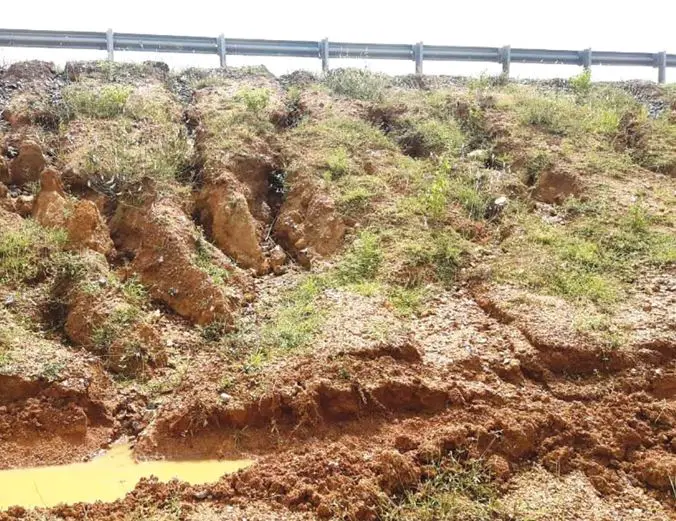
expansive soil
Figure 1: Expansive soil

The primary clay mineral behind the expansive behaviour of these soils is the presence of smectite clays, particularly montmorillonite. These clays possess a 2:1 layered structure with interlayer spaces that readily accommodate water molecules, causing the layers to expand and the soil volume to increase. Upon drying, the interlayer water evaporates, resulting in layer contraction and soil shrinkage. This cyclic wetting and drying process can lead to significant differential movements, differential settlements, and the formation of desiccation cracks in expansive soils.

Therefore, clay minerals are an important microscopic factor affecting the engineering behaviour of soils. This article explores the common clay minerals and how their properties affect the expansive behaviour of soils.

Building Blocks of Clay Minerals

The building blocks have two basic elemental units: the silicon tetrahedron and the alumino-magnesium octahedron. They are shown in a simplified way in Figure 2. The silicon tetrahedron consists of silicon and oxygen atoms. Since silicon has a 4+ valence, it can bond with negative ions like oxygen (O2-) or hydroxyl (OH), as seen in Figure 2(a). The relative sizes of the silicon and oxygen atoms make this structural unit take the shape of a tetrahedron.

building blocks of clay minerals
Figure 2. Atomic structure of silicon tetrahedra and alumino-magnesium octahedra: (a) silicon tetrahedron; (b) silica sheet; (c) symbolic structure for silica sheet; (d) alumino-magnesium octahedron; (e) octahedral sheet; (f) symbolic structure for octahedral sheet (after Lambe and Whitman, 1969; Mitchell and Soga, 2005).

The alumino-magnesium octahedron is made up of aluminium or magnesium atoms with hydroxyls around them, as seen in Figure 2(d). These atoms are placed so that they can be imagined as forming an octahedral shape.

In the silicon tetrahedron in Figure 2(a), the oxygen atoms have an unfulfilled chemical bond each. The oxygen atoms at the bottom of a tetrahedron are shared with nearby tetrahedra, and the resulting arrangement of tetrahedra makes sheets, as seen in Figure 2(b). Sharing of oxygen atoms among the tetrahedra satisfies the oxygen atoms at the bottoms of the tetrahedra, but the oxygen atoms at the tops still have unsatisfied bonds, as seen in Figure 2(b). So, the top face of the silica sheet can form chemical bonds with positive cations.

The octahedral units share hydroxyls to make a sheet structure, as seen in Figure 2(e). The placement of the octahedral units is such that the hydroxyls in the sheet structure have fulfilled chemical bonds. The central cation in the octahedral sheet can change.

The building blocks that are used to show the crystalline structure of the different clay minerals are represented by schematic symbols in Figures 2(c) and 2(f). By changing the way these two building blocks are arranged, different clay minerals can be formed.

Types of Clay Minerals

The different minerals are grouped according to the order of the sheets. For this article, we will only consider three basic clay minerals:

  1. Kaolinite
  2. Illite
  3. Montmorillonite

Figure 3 shows simplified diagrams of the structures of these three minerals. The bonding between the different building blocks is very important for the behaviour of the different minerals.

image
Figure 3. Schematic diagrams of the structure: (a) kaolinite; (b) illite; (c) montmorillonite.

The term bentonite is often used for expansive soils. This term means clays that have a lot of montmorillonite. Bentonite is a very plastic, swelling clay material that mainly has montmorillonite. It is mined for business and is used for many things like drilling fluids, slurry trenches, cosmetics, paint thickeners, and more. Not all expansive soils are bentonite, but they are often called bentonite, usually by people who are not engineers.

Kaolinite Clay Mineral

Kaolinite group minerals feature a 1:1 layered structure. Each layer consists of a single tetrahedral silica sheet directly bonded to an octahedral alumina sheet. Unlike the 2:1 structure of smectites like montmorillonite, the absence of an intervening octahedral sheet results in stronger interlayer bonding and minimal swelling behaviour.

kaolinite clay mineral
Figure 4: Mineral structure of kaolinite

The bonds between the silica and octahedral sheets affect the size of the mineral particles in a soil. The kaolinite structure in Figure 4 shows that there is a strong bond between the octahedral sheet and the top of the silica sheet. This is because of how the atoms are arranged and the fact that some of the hydroxyls in the octahedral sheets can be replaced by the oxygen atoms at the top of the silica tetrahedra. So, there is a strong chemical bond between the octahedral sheet and the silica sheet.

In Figure 3a, the chemical bonds at the bottom of the silica sheet are satisfied, and so, the bond between the octahedral sheet and the bottom of the silica sheet is mainly formed by weaker hydrogen bonds. That is called a weak bond. So, when the mineral breaks, the sheets will split at the weak bond. However, the bonds are strong enough that the clay particles can have a number of building blocks in each clay particle. Therefore, the kaolinite particles are relatively big with a lateral size of up to 1 micron (μm) or more, and a thickness of 1/3 to 1/10 of the lateral size.

Scanning electron micrograph of kaolinite
Figure 5: Scanning electron micrograph of kaolinite

Characteristics of Kaolin Clay Mineral

  • High chemical stability: Kaolinite exhibits exceptional resistance to weathering and chemical attack due to its strong covalent bonds and low reactivity.
  • Low cation exchange capacity (CEC): Compared to smectites, kaolinite possesses a significantly lower CEC due to the absence of exchangeable cations in the interlayer space.
  • High whiteness and brightness: The pure aluminium silicate composition and minimal iron impurities endow kaolinite with excellent whiteness and brightness, making it desirable for applications requiring high optical qualities.
  • Good rheological properties: The platy morphology and surface properties of kaolinite contribute to its ability to thicken and suspend particles in aqueous suspensions, essential for its use in various industrial processes

Montmorillonite Clay Mineral

Montmorillonite is a member of the smectite family, a group of 2:1 layered silicates characterized by a tetrahedral silica sheet sandwiched between two octahedral alumina sheets. This layered structure gives rise to several unique properties, including a large surface area, high cation exchange capacity (CEC), and the ability to intercalate guest molecules between the silicate layers.

structure of montmorrilonite
Figure 6: Montmorillonite clay mineral structure

The bond between the two silica sheets at the bottom is made by weaker van der Waals forces for the montmorillonite, and it is marked as “very weak” in Figure 2c, unlike just “weak.” Because of this, montmorillonite particles may have only one or two sets of building blocks in thickness. So, the clay particles may be very thin, about 10 Ångström or less.

The unit cell of montmorillonite consists of two silica tetrahedral sheets linked to a central octahedral alumina sheet via shared oxygen atoms. This basic structure forms repeating layers stacked upon each other with weak van der Waals forces holding them together. The negative charge on the basal oxygen atoms is balanced by exchangeable cations (commonly Na+, Ca2+, or Mg2+) residing in the interlayer space. These cations contribute to the high CEC of montmorillonite, enabling its selective adsorption of various cations and organic molecules.

Scanning electron micrograph of montmorillonite
Figure 7: Scanning electron micrograph of montmorillonite

Characteristics of Montmorillonite

  1. Swelling: The presence of exchangeable cations and hydration of interlayer space allows montmorillonite to expand significantly upon contact with water, leading to increased volume and plasticity.
  2. Adsorption: The high surface area and CEC of montmorillonite facilitate the adsorption of various pollutants, toxins, and organic molecules, making it useful for environmental remediation and water purification.
  3. Cation exchange: The selectivity of montmorillonite towards specific cations can be exploited for soil amendment, nutrient retention, and catalysis.
  4. Intercalation: Guest molecules, such as polymers and drug molecules, can be inserted into the interlayer space of montmorillonite, leading to the formation of nanocomposites with unique properties.

Illite Clay Mineral

Illite comprises a group of mixed-layer clay minerals with structural features mirroring both smectites and micas. Its basic 2:1 layer unit resembles that of smectites, featuring a single tetrahedral silica sheet sandwiched between two octahedral alumina sheets. However, unlike smectites, illite possesses interlayer potassium ions occupying vacant octahedral sites, resulting in stronger interlayer bonding and reduced swelling behaviour.

Structure of illite clay mineral
Figure 8: Structure of illite clay mineral

The illite particle has a similar structure to the montmorillonite particle. But in illite, the bond between the silica sheets at the bottom is made by potassium cations that are shared by nearby sheets. The potassium ions are the right size to fit into the gaps in the bottom of the silica sheet made by the tetrahedra. Sharing the potassium ions between the silica sheets makes a strong bond. So, the kaolinite and illite minerals are much less expansive than the montmorillonite.

Scanning electron micrograph of illite
Figure 9: Scanning electron micrograph of illite

Characteristics of illite clay minerals

  • Intermediate swelling behaviour: Compared to highly swelling smectites, illite exhibits minimal swelling upon hydration due to the presence of fixed interlayer potassium ions and stronger layer bonding.
  • Moderate cation exchange capacity (CEC): While lower than smectites, illite possesses a notable CEC due to the exchange of cations on the basal plane and edges, influencing its interactions with various cations and organic compounds.
  • High thermal stability: Due to its strong Si-O-Al bonds and stable interlayer potassium ions, illite exhibits exceptional thermal stability, making it suitable for high-temperature applications.
  • Excellent rheological properties: The platy morphology and surface properties of illite contribute to its ability to thicken and suspend particles in aqueous suspensions, valuable for its use in drilling fluids and other industrial processes.

Do’s and Don’ts of a Civil Resident Engineer

The Institution of Civil Engineers (ICE) conditions of contract in the UK allow the Engineer of a project to appoint a representative on site, typically called the Resident Engineer (RE), to oversee the construction and completion of the project (Clause 2(3)). The engineer can give the resident engineer any of their responsibilities and powers.

In this case, the Engineer refers to an independent engineer (registered engineer personnel or a consulting firm) appointed by the owners of the projects (client) to administer the contract on their behalf. Clause 2(8) of ICE conditions of contract mandates that this Engineer act impartially within the contract’s framework, considering all relevant factors. While the Engineer may be a consultant hired by the employer (client) or an internal staff member, this in no way compromises their obligation to remain unbiased in the contract administration.

As hinted in the opening paragraph of this article, the Engineer appointed by the client to administer a contract has the right to appoint a Resident Engineer who will act on his behalf on site. The resident engineer serves as an extension of the Engineer, exercising delegated powers with the same impartiality.

Resident engineer issuing instruction on site

Therefore, the resident engineer must always follow the engineer’s guidance and only use the authority given to him. He must understand that his actions represent the engineer, and so he must consult the engineer before doing anything he is unsure about. He can offer his ideas to the engineer, identify challenges and suggest solutions; and since he is always on site, he should alert the engineer of any potential issues. When making decisions, he must know his own technical limits and leave matters that need experts to the engineer or more qualified people to decide.

This article discusses the duties and functions that are delegated to the Resident Engineer and those that are not under the ICE conditions.

Functions Delegated to the Resident Engineer

It is typical for the resident engineer’s assigned responsibilities and authorities under the ICE framework to encompass, in whole or in part, the functions listed below.

  • Confirming the methods of construction details; ensuring that the contractor receives clear instructions and any necessary information on time. This means that the Resident Engineer has the power to review the construction methodology of the contractor. He also has the responsibility of providing answers and information good time to the contractor in relation to the success of the project.
  • Requesting and/or ordering all materials and items that the client will supply under other contracts and that will be part of the works in advance. The Resident Engineer must always request materials ahead of time in order not to incur unnecessary delays in the project.
  • Inspecting the materials and workmanship for quality and compliance; giving directions for fixing any defects.
  • Verifying the lines, levels, layout, etc. of the works to match the drawings.
  • Providing additional instructions, drawings and details as needed to achieve satisfactory construction of the works.
  • Assessing the amount of work completed, reviewing the contractor’s interim statements and getting them ready for the engineer’s approval.
  • Coordinating, supervising and performing all tests required and maintaining records of them. This may include soil tests, asphalt tests, concrete tests, steel tests, etc.
  • Documenting construction progress in detail; monitoring the estimated final total cost of the project.
  • Evaluating all claims from the contractor, collecting data related to such claims, and sending the contractor a preliminary reply to each claim.
  • Checking daywork sheets, price increases, and all other matters that need accountancy verification.
  • Inspecting the design of contractor’s temporary works for safety and quality of permanent works.
  • Serving as the engineer’s Safety Supervisor on site.
  • Informing the engineer of all the above in the way he wants.
civil engineers

Functions not Delegated to the Resident Engineer

According to the ICE conditions, there are some powers which the engineer cannot delegate to the Resident Engineer. Some of them are;

  • Certifying payments and time extensions for unforeseen challenges, difficulties, or obstacles.
  • Granting schedule flexibility to accommodate project needs. This means that the Resident Engineer does not have the authority to grant time extensions for project completion.
  • Issuing certificates marking key project stages (substantial completion, defects corrected, final payment)
  • Notifying the employer if the contractor abandons or seems unable to finish the project.
  • Making rulings on disagreements before formal legal mechanisms like adjudication or arbitration.
  • Issuing variation orders (VOs) or authorize payment to the contractor for delay
  • Approving the contractor’s programme for construction.
  • Issuing interim payment certificates;

The reason why the Resident Engineer may not be allowed to issue variation orders (VO’s) is to enable the engineer himself to scrutinize both the rationale and the financial implications of any proposed variation order (VO). Notably, for overseas projects, the resident engineer might be entrusted with the authority to issue VOs and interim payment certificates. In such situations, the resident engineer would typically have a qualified on-site team to meticulously review proposed VOs and interim payments before authorizing them.

It is important to note that the contractor will likely refuse to carry out any changes to the work that the Resident Engineer asks for unless he gets a VO from the engineer beforehand. This implies that the contractor expects to be informed of the payment for the changed work. The RE should usually be able to tell how the payment for the changed work will be done. However, the contractor has to follow the instructions and do the work as asked and the engineer will have to give a VO that specifies the payment rates as per the contract.
Extra Guides for Resident Engineers on Site

Some of the points that a Resident Engineer must watch out for on-site are as follows;

  1. All instructions given to the contractor must be in writing, and if given verbally, must get to them in writing ‘as soon as the situation allows’ (Clause 2(6)(b)).
  2. If the contractor gets a verbal instruction and writes it down, and the engineer does not disagree with it ‘immediately’, then the written confirmation is ‘considered a written instruction by the engineer’ (Clause 2(6)(b)). These written confirmations of oral instructions – or ‘CVIs’ as they are known – can cause problems for the RE.
  3. Even if a Resident Engineer does not have the authority to determine how much should be paid (if any) for a contractor’s request for extra payment, he can write to the contractor and express his opinion on the request. He must do this, in every case, so that the record shows his perspective on the facts.
  4. There are many ‘time clauses’ in the contract conditions, that is, clauses that set a deadline for the engineer (and probably the RE too) to act. A key example is the obligation that the engineer must give feedback on the contractor’s planned programme within 21 days of getting it, otherwise, the engineer is assumed to have approved it (Clause 14(2)). The same, essentially, applies to any partial programme or updated programme the contractor provides. Therefore if the engineer does not give feedback within 21 days, the contractor’s programme is assumed to be accepted and inconsistencies may arise if the programme does not match the specified timing.
  5. The RE must make sure that the contractor gets all the approvals, drawings, details and other information he requires to build the works, in a timely manner; otherwise, the contractor may ask for compensation for delay (Clause 7(4)).
  6. The RE must not allow lower quality materials or workmanship than what is specified, even if the contractor proposes a lower price than the bill price for the specified material unless the engineer consents to this. Such a change is a variation that needs a VO.
  7. The RE has to notify the contractor right away when he notices any flaws in materials or workmanship, because it may be very hard to fix a faulty part of the work after it is finished. Therefore quality checks should happen as soon as an activity begins, or as soon as material for the permanent works arrives at the site.


Composite Box Girder Bridges

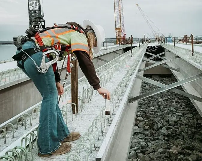
Composite box girders can be an attractive option for medium-span highway bridges. They offer an aesthetically pleasing appearance and speedy construction procedures for bridges. The design and construction techniques already popular for the I-beam form of composite bridges can be used to produce box girder structures.

Composite bridges are structures that combine materials such as steel, concrete, timber or masonry in any combination. In this context, however, composite construction is usually taken to mean either steel and in-situ concrete construction or precast concrete and in-situ concrete bridges. In composite box girder bridges, it is generally accepted that replacing concrete webs with steel will lead to a significant reduction in the weight of the structure.

The boxes may be complete steel boxes with an overlay slab, or an open box where the concrete slab closes the top of the box. The use of the open steel box section allows the reintroduction of a bottom concrete compression flange at hogging moment regions by in-filling over supports giving a doubly composite section. This design concept can be used for spans ranging from about 45 m to 100 m.

Composite box girder bridge

Box girder bridge structures have much greater torsional stiffness than I-beam structures. This feature differentiates their behaviour. The prime effect this has on global bending behaviour is to share the vertical shear more equally between the web planes.

This guide assumes that spans are greater than 45 meters and that the position of supports is largely determined by physical constraints, at least for the major span. However, the bridge may consist of successive spans over land, and the designer may have the freedom to vary span lengths. The selection of a span length will require consideration of the costs of both sub- and super-structure, and a balance will have to be struck for overall economy. The foundation conditions and their consequent cost strongly influence this balance.

Why Composite Box Girders?

According to The Steel Construction Institute (SCI, 2004), box girder bridges and I-beam bridges require approximately the same weight of steel. However, it has been discovered that composite box girders can be optimized to make the best use of their advantages, which can lead to slightly less steel usage. Deck slab thickness is normally similar for both forms of construction. With box girders, torsionally stiff beams can often reduce the number of bearings or support positions, leading to a more slender sub-structure.

Moreover, curvature is more easily achieved with box girders. Although curvature of girders in plan is not common in the UK, box girders can effect curvature much more readily if true plan curvature is wanted, either for appearance or because the radius is unusually tight. I-beams would require significant transverse bracing in these situations.

Furthermore, box girders may prove more expensive than I-beam girders and slab construction in terms of simple capital cost of the superstructure for straight bridges, the advantages of the box girder form, such as better appearance and reduced maintenance, may well merit the evaluation of a box girder as an alternative for any bridge in the span range of 45 m to 100 m. For bridges with a significant plan curvature, box girders should always be considered.

Section Depth

The construction depth of a parallel-flanged composite box girder is typically between 1/20 and 1/25 of the major span. Shallower sections can be used, with possible benefit to appearance, at the expense of greater weight. Variable depth sections are relatively straightforward with rectangular sections and can give an attractive slender appearance, particularly over a river.

Variable cross-section composite box girder bridge

Curved soffits require internal transverse flange stiffeners to resist the radial component of force, though this is not onerous with large radii. Curvature is usually applied only to the major span and to the spans on either side of it.

With trapezoidal sections, a variation in depth will result in either a change in the width of one of the flanges along the bridge, or the web inclination will change. The appearance of the latter is likely to be somewhat disquieting, unless unnoticeably minor, and the former is to be preferred. Indeed, when well executed the former arrangement can produce a particularly good appearance.

Initial selection of flange and web sizes

The flange and web sizes depend on the configuration of the cross-section and the bending/torsional moments to be carried. A first estimate of sizes can be based on simple approximations and quickly refined to a better initial selection suitable for use in the detailed design.

The first rough estimate is used to determine properties for a simple grillage model, which is used to give a better indication of the distribution of bending moments so that a better initial design can be made. Several iteration cycles are likely to be needed at this stage.

The girders will be made up of several sections, in lengths suitable for transportation. This gives scope for variation of make-up between the different sections. At the initial design stage, splice positions should be considered and advantage taken to change plate thicknesses where appropriate. The main girders should normally be structural steel to grade S355 of BS EN 10025 since it is more cost-effective than lower grades.

Typical Construction Considerations of Composite Box Girder Bridges

The preliminary design of composite box girders should take into account their construction, performance, and maintenance. A composite box girder is not just a pair of plate girders with a common bottom flange. If proper account is not taken during the initial stage, the design will be less efficient and is likely to give rise to problems later which will be difficult to overcome.

Construction methodology: The designer should understand how the composite box girder is constructed. The flanges and webs will be fitted with stiffeners before they are assembled. Cross-frames or diaphragms will be needed at this stage to ensure that the cross-section is held in shape during welding. Closed trapezoidal boxes are usually assembled in an inverted position and the bottom flange is added last of all.

Internal Welding: Internal welding after closure is usually necessary; support diaphragms at least must be welded all around. Access and ventilation are more easily arranged in the shop than on site but even so, the amount of internal welding should be minimized where possible. It is difficult to ensure perfect alignment of every web and flange transverse stiffener at the corners and a connection detail, such as lapping, which will accommodate small differences should be chosen.

Type of welding: Joints between flanges and webs are easier and cheaper to make as fillet welds, rather than as butt welds. Butt welds are used in box girders for railway loading, where fatigue is more onerous; they are not necessary for highway bridges.

Transportation: After assembly, the box will have to be transported. In the UK, there are limits on length (27.4 m long) and width (4.3 m wide) for unrestricted travel on public roads, but larger sizes can be carried by special permission. Advice should be sought from the appropriate highway authority for travel in the relevant localities.

Stiffeners: Fitting and welding of stiffeners is expensive, and it is often cheaper to use thicker plate with less stiffening. Butt welds allow a change of plate thickness where stresses are lower, but making the weld may be more expensive than using the thicker plate throughout an individual length of girder.

Splices: Bolted splices are quicker to make on site, but sealing details at the ends of cover plates must be considered. If welding is used for the web and flange splices, bolting can still be effective internally for splicing longitudinal stiffeners. Such stiffeners should always be spliced with cover plates because true alignment is very difficult to achieve.

Support Bearing: Articulation arrangements (the configuration of fixed, guided, and free bearings) should be established at an early stage so that bearing positions, bearing stiffener requirements, and the need for bracing between boxes at supports can be determined.

Internal Drainage: It is important to consider drainage internally and avoid closed corners where moisture and dirt can collect. Composite box girders in this span range are often compared with prestressed concrete box girders. In such a comparison, the advantages of the steel girder in speed and ease of construction on site should be fully recognized.

Corrosion Protection and Inspection: Externally, the surface of the steel girder is durable, using modern protection systems or weather-resistant steel. Internally, the environment is closed and should require no more than routine inspection.

Contractor’s Experience: Advice on fabrication details and construction schemes should be sought from an experienced fabricator during the design stage, though it must be recognized that individual fabricators have particular preferences arising from their experience and workshop facilities.

Construction Joints in Structures

Concrete joints are essential components of various structures and are implemented on construction sites based on specific construction requirements and design considerations. Construction joints in concrete structures are almost unavoidable, given that structures cannot be built in a single casting step. Therefore, with the presence of joints, building the structure piece by piece is possible until it becomes a complete whole.

There are different types of joints in concrete such as movement joints, contraction joints, expansion joints, sliding joints, construction joints, temporary joints, and isolation joints. Some of these joints can exist in structures of different configurations, addressing specific technical needs based on the design and nature of the structure.

Construction Joints

Construction joints are deliberate separations or discontinuities created within concrete structures. In other words, construction joints allow for the placement of concrete in stages. This is because it is not practical to pour concrete for an entire structure in a continuous manner, except for small construction works. 

For example, depending on the technical capacity of the contractors, it may not be feasible to pour the concrete of a floor and the continuation columns of the floor on the same day. Moreover, the maximum quantity of concrete that may be mixed and placed on the construction site is also determined by the batching and mixing capacity, the number of the workforce, and the allocated time duration.

In effect, accurately positioned and effectively implemented construction joints establish boundaries for consecutive concrete placements, without causing any negative impact on the structure. A properly constructed joint in monolithic concrete ensures a robust and watertight surface, allowing the joint to maintain its flexural and shear continuity. In the absence of this continuity, the region becomes weaker, potentially functioning as a joint for either contraction or expansion.

Continuity of reinforcement is critical in construction joints

Preparation of Construction Joint Surfaces

To establish a strong and impermeable joint, several prerequisites must be met before the application of the newly poured concrete. It is necessary for the concrete to be thoroughly cleaned and free of any laitance residue.

When there is a short period of time between consecutive placements, it is essential to visually inspect and ensure that any loose particles, dirt, and laitance have been thoroughly removed. To ensure proper bonding between the new concrete and the hardened concrete, the new concrete should be extensively vibrated throughout the entire area.

For more mature joints, additional surface preparation is required. The concrete can be cleaned using an air-water jet or wire brooming while it is in a state where the laitance can be removed but the aggregate remains securely in place. To prepare hardened concrete, it is recommended to use either a wet sandblast or an ultra-high-pressure water jet, as stated by the ACI Committee 311 (2019).

According to ACI 318, it is necessary to thoroughly dampen the existing concrete before placing fresh concrete. Green concrete does not require any more water, but concrete that has dried up may require saturation for a duration of one day or longer. During concrete placement, there should be no stagnant water on the wet surface.

Location of the joint

When designing construction joints, it is important to consider the precise placement or location of the joint in the structure. If construction capacity allows, construction joints should be positioned in a way that minimizes the impact on the structural strength of the structure while still being in harmony with the building’s aesthetics.

The positioning of joints varies depending on the nature of the element being constructed. To provide clarity, beams and slabs will be discussed as distinct entities from columns and walls.

construction joint for different phases of pour

Beams and slabs

When it comes to the structural integrity of beam and slab floor systems, it is recommended to position joints perpendicular to the main reinforcement at sites where shear is minimal or at points of contraflexure. At the point of contraflexure, the bending moment is expected to be very minimal. Therefore, it is going to be the least stressed section of the structure.

Typically, joints are placed at the midpoint or within the central third of the span, but their exact placement should be confirmed by the structural engineer. According to ACI 318, in beam and girder construction, when a beam crosses a girder at the place where the shear is minimal, the construction joint in the girder should be positioned at a distance that is twice the width of the incident beam.

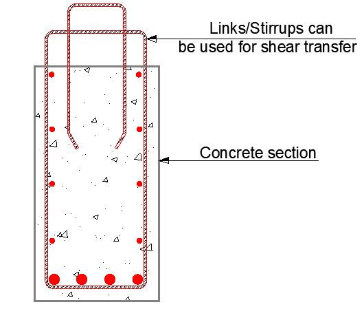
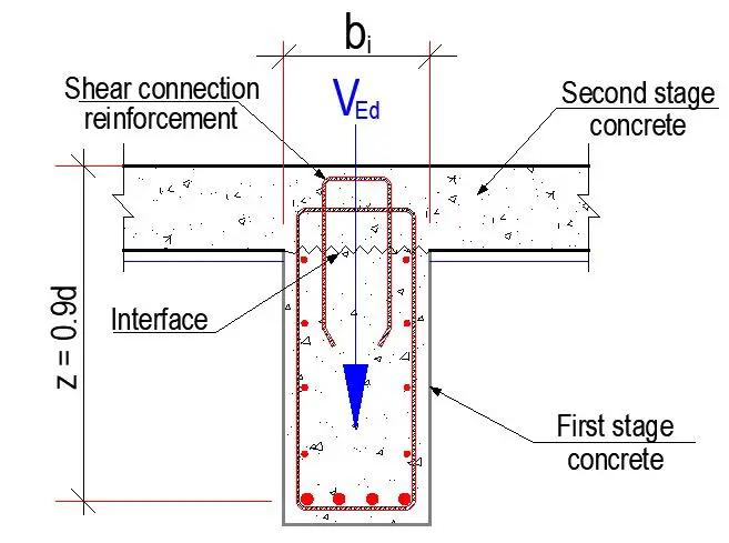
It is often discouraged to use horizontal construction joints in beams and girders. A conventional approach involves integrating beams and girders seamlessly with the slab. To achieve flexural continuity, it is necessary to extend the reinforcement through the joint with a length that is sufficient to provide an appropriate splice length for the reinforcement. Shear transmission occurs through either shear friction between the existing and new concrete, or dowel action in the reinforcement across the joint.

In Nigeria, it is usually typical to cast the beams of a suspended floor first, when it is not feasible to cast the entire floor in a single pour. At the subsequent casting, the slab deck is poured to sit on the hardened beam.

Columns and Walls

When it comes to concrete placement, it is common practice to limit the height of concrete to one story. Construction joints in columns and bearing walls should be positioned at the lower surfaces of floor slabs and beams, and at the upper surface of floor slabs for columns that extend to the subsequent floor. The column capitals, haunches, drop panels, and brackets must be integrated seamlessly with the slab.

The positioning of newly poured concrete on a level surface can impact the connection point. Traditionally, it is customary to apply a layer of mortar, with the same proportions as the concrete, before pouring new concrete over the joint. The ACI Manual of Concrete Inspection (ACI Committee 311, 2019) recommends using a bedding layer of concrete that contains a slightly higher proportion of cement, sand, and water than the design mix specified for the project.

Material measuring less than 3/4 inch can remain in the bedding layer, whereas any material above 3/4 inch should be removed. The recommended depth for placing this mixture is between 4 to 6 inches, and it should be vibrated vigorously along with the standard mixture placed on top.

Conclusion

Construction joints play a crucial role in the performance and buildability of reinforced concrete structures. They serve as specially selected interfaces between different sections or phases of a structure, during the concrete pour. Construction joints are typically formed by placing a layer of concrete, then allowing it to set before placing the next layer. The joint is then formed by removing any loose material and cleaning the surface of the concrete. 

It is important to ensure that there is continuity of reinforcements at construction joints to ensure maximal shear transfer between the joints. Furthermore, in flexural members, joints should be located where stresses are minimal, while in compression members such as columns and walls, they should be preferably located at the top and bottom of the members.

Construction joints are crucial elements in ensuring the structural integrity, constructability, and aesthetics of concrete structures. Understanding their types, design considerations, and benefits helps optimize their role in creating safe, durable, and visually appealing buildings.

Geostatic (In-situ) Stresses and At-Rest (K0) Condition in Soils

The stress in the soil mass is affected by the previous loading history. When a new foundation is constructed, the new load can either increase or decrease the existing stresses in the soil. The response of the soil mass to the new load depends on the previous stress history. Therefore, it is important to understand the stress imprint of the soil mass before designing a foundation.

The term “stress imprint” refers to the state of stresses that are locked into the soil structure. These stresses are locked in because the soil particles have rearranged and formed bonds. The bonds prevent the stresses from being released, even when the load is removed. The stress imprint can be either positive or negative.

image 20
Figure 1: Stresses in a soil mass

A positive stress imprint is created when the soil is loaded to a higher stress than it is currently experiencing (normally consolidated soil). A negative stress imprint is created when the soil is unloaded to a lower stress than it is currently experiencing (overconsolidated soil).

The stress imprint can affect the behaviour of the soil in a number of ways. For example, a positive stress imprint can make the soil more resistant to shearing, while a negative stress imprint can make the soil more susceptible to settlement.

The stress imprint can be difficult to measure, but there are a number of techniques that can be used. One common technique is to use a pressuremeter. A pressuremeter is a device that is inserted into the soil and used to measure the stresses in the soil.

In-Situ Stresses in Soil

In situ, the vertical stresses act on a horizontal plane at some depth z. These can be computed in any general case as the sum of contributions from n strata of unit weight γi and thickness zi as;

po = ∑γizi —— (1)

In the context of the formation of soil deposits, the area of the land where soil accumulates is typically extensive, and the depth of the deposit keeps increasing until either the accumulation process or the internal weathering process halts. This transition leads to a gradual downward compression of the soil at any specific depth.

Likewise, the vertical stress also increases due to this compression, and in almost all instances, the unit weight of the soil is a function of depth. Given the substantial lateral extent of the deposit, there is limited justification for notable lateral compression to take place.

Consequently, it is reasonable to anticipate that the vertical locked-in effective stresses (p’o) would surpass the effective lateral stresses (σ’h) at the same location. This relationship between horizontal and vertical stresses can be defined as the ratio of the two.

K = σh/po ——– (2)

which is valid for any depth z at any time.

K0 Conditions

Over geological time the stresses in a soil mass at a particular level stabilize into a steady state and strains become zero. When this occurs the vertical and lateral stresses become principal stresses acting on principal planes. This effective stress state is termed the at-rest or K0 condition with K0 defined as;

K0 = σ’h/p’o ——– (3)

Therefore, Ko conditions refer to the state of stresses in a soil mass when there is no lateral strain. This means that the soil is not allowed to deform horizontally. Ko conditions are typically found in undisturbed soil, where the soil has not been subjected to any significant lateral stresses.

Figure 2 shows the range of K0 and the relationship between po and σh in any homogeneous soil. The figure also shows the qualitative curves for preconsolidation in the upper zone of some soil from shrinkage/chemical effects. The figure clearly illustrates the anisotropic (σv ≠ σh) stress state in a soil mass.

image 10
Figure 2: Qualitative vertical and lateral pressures in a soil.

In the figure above, although the linear vertical (also called geostatic) pressure profile is commonly used, the p’0 effective pressure profile is more realistic of real soils since γ usually increases with depth. The lateral pressure profile range is for the geostatic pressure profile and would be curved similarly to the p’o curve for real soils.

K₀ conditions are critical for:

  • Retaining wall design.
  • Excavation support.
  • Earthquake-induced lateral pressures.
  • Soil-structure interaction.

Because of the sampling limitations, it is an extremely difficult task to measure K0 either in the laboratory or in situ. Some field methods are available, but note that they are very costly for the slight improvement—in most cases—over using one of the simple estimates following. In these equations use the effective angle of internal friction ‘ and not the total stress value.

Jaky (1948) presented a derived equation for K0 that is applicable to both soil and agricultural grains (such as corn, wheat, oats, etc.) as;

K0 = [(1 – sinφ’)/(1 + sinφ’)] × ( 1 + 2/3sinφ’) ——– (4)

which has been simplified—and erroneously called “Jaky’s equation”— to the following:

K0 = 1 – sinφ’ ——— (5)

This equation is very widely used and has proved reasonably reliable in comparing initial to back-computed K0 values in a number of cases and for normally consolidated materials. Kezdi (1972) suggests that for sloping ground Jaky’s equation can be used as follows:

K0 = (1 – sinφ’)/(1 + sinβ) ——– (6)

where β is the angle with the horizontal (with sign) so that K0 is either increased or reduced as site conditions dictate. This reference also gives a partial derivation of the Jaky equation for any interested user.

Brooker and Ireland (1965) (for normally consolidated clay) suggest;
K0 = 0.95 – sinφ’ ——– (7)

Alpan (1967) (for normally consolidated clay) suggests;
K0 = 0.19 + 0.233 log10 Ip ——– (8)

An equation similar to Eq. (8) is given by Holtz and Kovacs (1981) as;
K0 = 0.44 + 0.0042Ip ——– (9)

where Ip is the plasticity index of the soil in percent.

We can readily derive a value for K0 in terms of Poisson’s ratio based on the definition of K0 being an effective stress state at zero strain. From Hooke’s law, the lateral strain in terms of the effective horizontal (x, z) and vertical (y) stresses is;

εx = 0 = 1/Esx – μσy – μσz) = εz ——– (10)

For a cohesionless, soil μ is often assumed as 0.3 to 0.4, which gives K0 = 0.43 to 0.67, with a value of 0.5 often used. It is extremely difficult to obtain a reliable estimate of K0 in a normally consolidated soil, and even more so in overconsolidated soils (OCR > 1). A number of empirical equations based on various correlations have been given in the literature. Several of the more promising ones are:

Alpan (1967) and others have suggested that the overconsolidated consolidation ratio K0,OCR is related to the normally consolidated value K0,nc in the following form;

K0,OCR = K0,nc × OCRn (2-23) ——– (11)

where n = f(test, soil, locale) with a value range from about 0.25 to 1.25. For overconsolidated sand, n can be estimated from Figure 3.

image 19
Figure 3: Exponent n for sands.

For cohesive soil, Wroth and Houlsby (1985) suggest n as follows:

n = 0.42 (low plasticity — IP < 40%)
n = 0.32 (high plasticity — IP > 40%)

However, n ≈ 0.95 to 0.98 was obtained from in situ tests on several clays in eastern Canada. Mayne and Kulhawy (1982) suggest that a mean value of n = 0.5 is applicable for both sands and clays and that n = sinφ’ is also a good representation for sand. Their suggestions are based on a semi-statistical analysis of a very large number of soils reported in the
literature.

The exponent n for clays was also given by Alpan (1967) in graph format and uses the plasticity index IP (in percent). The author modified the equation shown on that graph to obtain;

n = 0.54 × 10(-IP/281) ——– (12)

And, as previously suggested (for sands), we can use;

n = sinφ’ ——— (13)

Conclusion

Geostatic conditions refer to the stress state within a soil mass due to the weight of the overlying soil. These stresses are primarily vertical and compressive, but they also induce horizontal stresses due to the frictional resistance of the soil particles. The magnitude of these stresses depends on the depth of the soil layer, the unit weight of the soil, and the geometry of the soil mass.

The K0 condition, also known as the at-rest earth pressure, represents a specific stress state within a soil mass where there is no lateral strain. This condition occurs when the soil is horizontally constrained, such as by a retaining wall or a layer of bedrock. In K0 conditions, the horizontal effective stress (σ’h) is typically about 0.5 to 0.7 times the vertical effective stress (σ’v). The factors affecting K0 values are the overconsolidation ratio, type of soil, confining pressure, stress history, and effective stress state.

Design of Fillet Weld Connections

In modern construction, the commonest methods of connecting steel members are bolting and welding. Fillet welds are generally used for connecting parts where the fusion faces form an angle of between 60° and 120°. Although there are other special cases and generalities stated in the code regarding fillet weld (kindly refer).

EN 1993-1-8 (Eurocode 3 Part 8) identifies different types of welding such as;

  • fillet welding
  • butt welding
  • plug welding,
  • and flare groove welds.

The effective weld thickness, denoted as ‘a‘, is determined by measuring the height of the largest inscribed triangle inside the fusion faces and the weld surface. This measurement is taken perpendicular to the outer side of the triangle, regardless of whether the triangle has equal or unequal legs.

image 18
Figure 1: Fillet weld thickness for different penetration

Types of Fillet Welds

There are three main types of fillet welds:

  • Equal leg fillet welds: These welds have legs of equal length.
  • Unequal leg fillet welds: These welds have legs of different lengths.
  • Lap fillet welds: These welds are used to join two pieces of metal that are overlapping.
fillet weld connection

Fillet Weld Design

The design of a fillet weld depends on the thickness of the metal being welded, the strength of the weld required, and the type of weld being used. The following factors should be considered when designing a fillet weld:

  • Weld size: The weld size is the length of the weld leg. The weld size should be large enough to provide the required strength but not so large that it causes distortion of the metal.
  • Weld throat: The weld throat is the thickness of the weld. The weld throat is typically equal to 0.7 times the weld size.
  • Weld length: The weld length is the length of the weld along the joint. The weld length should be long enough to provide the required strength but not so long that it is wasteful of material.

According to clause 4.5.3.1(1) of EN 1993-1-8, the design resistance of a fillet weld should be determined using either the directional method or the simplified method.

Directional Method

The directional method is based on the comparison between the design tensile strength and the applied stress in the most severely loaded part of the weld throat. When using the directional method for analyzing fillet welds, the force acting on the weld is divided into components that run parallel and perpendicular to the weld throat plane. This results in evenly distributed normal and shear stresses.

The applied stress, being determined from a Von Mises formulation, accounts for the influence on the weld strength of the inclination of the resultant force per unit length to the weld axis and plane.

In the directional method, a uniform distribution of stress is assumed on the section of the weld, leading to the normal stresses and shear stresses shown in Figure 2, as follows:

σ⊥ normal stress perpendicular to weld axis
σ|| normal stress parallel to weld axis
τ⊥ shear stress (in plane of fillet weld surface) perpendicular to weld axis
τ|| shear stress (in plane of fillet weld surface) parallel to weld axis

directional method fillet weld
Figure 2: Stresses in a weld

Simplified Method

The simplified method is based on the design shear strength of the weld which is compared directly to an applied weld throat shear stress obtained by dividing the resultant force per unit of length of the weld throat size. This method does not necessitate determining the individual stress components within the weld.

Instead, the overall stress is calculated as the vector sum of all force components, and the weld’s strength is assumed to be equal to its shear strength, regardless of the force’s direction. Since fillet welds are weakest under pure shear, this method consistently produces more conservative results than the directional method.

Design Example

For the welded connection (K-Joint) in a steel truss given as shown below, establish the minimum throat thickness of the fillet weld for the gusset plate. The basic assumption is that the gusset plate transfers axial forces acting in its plane and in the direction of the member axes.

DESIGN%2BOF%2BWELDED%2BCONNECTION%2BFOR%2BROOF%2BTRUSS


Analysis Results

NA,Ed = 250 kN (compression)
NB,Ed = 250 kN (compression)
NC,Ed = 17.5 kN (compression)
NB,Ed = 17.5 kN (compression)

Geometric Data
Gusset plate thickness      tg = 10mm
Web thickness                  tw = 8mm
Angle between gusset and web      αa = 90°
Number of fillet welds      na = 1
Length of weld                  L= 400mm
Effective throat thickness a = ?

Material Data
Steel grade = S275
Yield strength fy = 275 N/mm2
Ultimate tensile strength fu = 430 N/mm2
Partial factor (resistance of weld) γM2 = 1.25 (recommended)

Design forces in the gusset plate at the chord web face
The effects of the small eccentricity from the chord axis will be neglected.
The gusset plate section is verified for the following forces:

Ng,Ed is the axial force at an eccentricity of ez = 0  to the centreline of the gusset plate
Vg,Ed is the shear force

nhyy

αi = 35°
Ng,Ed =  2(250 cos 35) = 409.576 kN
Vg,Ed =  2(250 sin 35) = 286.788 kN

Assuming a uniform distribution of load in the section, the normal stress is given by;

Normal%2Bstress

Ag is the cross-sectional area and it is given by Ag = tg. Lw = 10mm × 400mm = 4000 mm2

σg,max = (409.576 × 1000) / (4000) = -102.394 N/mm2

The mean shear stress is given by;
τg,max = (286.788 × 1000) / (4000) = 71.697 N/mm2

By directional Method;
Assuming a uniform distribution in the throat section of the weld;

σ = the normal stress to the throat plane
τ = the shear stress (in the plane of throat) perpendicular to the axis of the weld
τ// = the shear stress (in the plane of throat) parallel to the axis of the weld

On the throat section of the weld, the force per unit length are:

dfgh

Where eg is the average eccentricity. In our own case, we will be taking the eccentricity as unity.

a σ = [(102.394 × 1.0) / 1.0] / (sin 45°) = 72.403 N/mm2
τ = [(102.394 × 1.0) / 1.0] / (cos 45°) = 72.403 N/mm2

awee

a τ// = [(71.697 × 1.0) / 1.0] = 71.697 N/mm2

The design resistance of the fillet weld will be sufficient if the following conditions are both fulfilled:

drty

σw = [72.4032 + 3(72.4032 + 71.6972]0.5 = 190.762 N/mm2
βw = 0.85 (Table 4.1 EN 1993-1-8:2005)

Therefore;
f/ βwM2 = 410 / (0.85 × 1.25) = 385.882 N/mm2

190.762 N/mm2 < 385.882 N/mm2    OK

Also verify;
0.9f/ γM2 = 0.9 ×  410 / (1.25) = 295.2 N/mm2
72.403 N/mm2 < 295.2 N/mm2    OK

From these conditions, a minimum value for the effective throat thickness can be derived;

Throat%2Bthickness%2Bformular%2Bfor%2Bwelding

a1,min = 190.762 / 385.882 = 0.494 mm
a2,min = 72.403 / 295.2 = 0.245 mm
amin = max[a1,min , a2,min ] = 0.494 mm

However according to clause 4.5.2(2), the effective throat thickness of a fillet weld should not be less than 3mm, therefore, adopt 4mm effective throat thickness.

By Simplified Method

The design resistance of a fillet weld may be assumed to be adequate if, at every point along its length, the resultant of all the forces per unit length transmitted by the weld satisfies the following criterion (see Eurocode 3, Part 1-8):

Fw,Ed ≤ Fw,Rd

Where Fw,Ed is the design value of the weld force per unit length and Fw,Rd is the design weld resistance per unit length. The design strength resistance per unit length (Fw,Rd) is given by;

Fw,Rd = Fvw,d a

Where Fvw,d is the design shear strength of the weld and a is the throat thickness of the weld.

fwdv

Fw,Ed = τg,max = (286.788 × 1000) / (400) = 716.97 N/mm (shear force per unit length of weld)
fvw,d = (430 / √3) / (0.8 ×  1.25) = 233.657 N/mm2

Assuming a weld throat thickness of 4 mm
Fw,Rd = Fvw,d a = 233.657 × 4 = 934.628 N/mm
Fw,Ed  (716.97 N/mm) <  Fw,Rd  (934.628 N/mm) Ok

Note: 
According to clause 4.5.1(2) of EN 1993-1-8:2005, a fillet weld with an effective length less than 30 mm or less than 6 times its throat thickness, whichever is larger, should not be designed to carry load.

Thank you for visiting Structville today. 
Our facebook page is at www.facebook.com/structville

Strengthening Flat Slabs against Punching Shear

strengthening flat slab against punching shear

Punching shear is one of the most critical failure modes in flat slabs, characterized by its catastrophic and brittle nature. In existing buildings, there may come a time when there is a need for strengthening flat slabs against punching shear failure.

A flat slab is a type of suspended floor without beams, allowing for direct transfer of loads from the slab to the columns. They are frequently employed in building construction due to their ease of construction (especially in formwork and reinforcement placement), cost efficiency, and ability to accommodate lower floor heights. A flat slab construction, however, experiences significant transverse loads concentrated around the column, which can result in non-ductile, sudden, and brittle punching failure.

Most design codes worldwide have well-established design guidelines to prevent punching shear failure during the design process. Incorporating steel reinforcement, such as stirrups, shear heads, or shear studs, in the high shear zone enhances ductility, a crucial requirement in the design process.

punching shear failure
Figure 1: Typical punching shear failure

However, there are several factors that can lead to a decrease in the punching shear strength of flat slabs. These include casting concrete with a compressive strength lower than the intended value, incorrectly placing the punching shear reinforcement, and neglecting tension forces caused by shrinkage restraint or temperature changes, which have been shown to reduce the shear strength of the concrete.

Additionally, insufficient punching shear capacity of flat slab structures can be attributed to factors such as changes in usage and loading, new installations, or design and construction errors. Sometimes, this necessitates either upgrading existing structures or replacing them entirely. However, replacing deficient structures is often not a feasible option due to the substantial costs involved. Therefore, repairing and/or strengthening inadequate structures represents a viable solution, offering cost and time savings.

Strengthening is necessary to regain or improve the punching shear strength of the slab in this situation. To enhance the structural integrity, one can employ several methods such as incorporating drop beams, increasing the thickness of the slab near the columns with steel or concrete caps, or introducing punching shear reinforcement.

Techniques for Strengthening Flat Slabs against Punching Shear

To enhance the punching shear capacity of a flat slab-column connection, one can employ methods such as using a thicker slab, a larger column, concrete with higher compressive strength, more flexural reinforcement, or more shear reinforcement. These options can be generally categorised into;

In any project, some techniques for increasing the punching shear capacity of flat slabs are better than others, especially when considering architectural features and cost. Some exclusive methods of strengthening flat slabs against punching shear are discussed below;

Slab Strengthening by Columns Caps

Steel or concrete caps can be used at the top of columns to shift the critical section of the slab in punching shear away from the column face, thereby increasing the overall punching shear capacity of the slab. A typical steel cap used for slab strengthening is shown in Figure 2.

Punching shear strengthening using steel caps
Figure 2: Punching shear strengthening using steel caps (Abdelrahman, 2023)

The steel cap is attached to the column and the slab soffit using steel dowels. Steel stiffeners are used to increase the flexural stiffness of the steel plates attached to the slab. Grout is used to fill the gap between the steel cap and the bottom slab soffit to ensure good contact between the cap and the slab soffit. Strengthening efficiency will be greatly reduced if cracks or small gaps exist between the slab and the cap, as no vertical deformations of the slab are expected in this zone under the effect of gravity loads.

Punching Shear Reinforcement

To enhance the overall punching shear strength of the slab, it may be necessary to add steel reinforcement. The main types of shear reinforcement used for enhancing punching shear capacity are;

  • anchored bolts with nut, washer and plate
  • headed bolts
  • bonded bolts
  • grids or fans (only for composite materials)
  • stirrups (only for composite materials)

This process usually involves drilling through the slab near the column, where the flexural steel reinforcement is often densely packed. To prevent the need for cutting steel rebars during slab drilling, one can utilize steel detecting equipment to accurately locate the reinforcement.

image 12
Figure 3: (a) Anchored bolts with nut, washer and plate (b) headed bolts

After identifying the rebars, holes with a diameter bigger than that of the stirrups are drilled. The steel shear bars are then put through these holes and secured to the top and bottom concrete soffits using steel nuts, as depicted in Figure 4. To safeguard the steel bars and prevent corrosion, it is imperative to pump epoxy into the holes.

image 13
Figure 4: Strengthening flat slabs using shear reinforcements (Abdelrahman, 2023)

The quantity of shear bars is established according to the design specifications and the aspect ratio of the columns. The design standard dictates that the entire area of the steel bars at the critical section must be determined.

Use of FRP Sheets

Glueing fibre-reinforced polymer (FRP) strips in both perpendicular directions of the slab around the column head can enhance the slab’s flexural capacity. Employing bonded FRP strips in both orthogonal directions as a strengthening technique solely impacts the load-rotation curve, whereas the failure criterion remains relatively unchanged. The load-rotation curve post-strengthening exhibits increased stiffness due to the augmented longitudinal reinforcement.

frp sheets strengthening
Figure 5: Use of FRP sheets in slab strengthening

Generally, this method of flat slab strengthening enhances the punching shear resistance but diminishes the ductility of the connection. The failure becomes more brittle as the maximum rotation after reinforcement is lower than that of the current slab. The efficacy of this strengthening technique is closely tied to the quantity of flexural reinforcement in the existing slab.

Bonded Reinforced Concrete Overlay

A bonded reinforced concrete overlay (BRCO) may be used if the fibre-reinforced polymer (FRP) strengthening is insufficient to reach the desired punching capacity. The application of a BRCO (Figure 6) may be included in the flexural strengthening techniques, but it actually affects both the failure criteria and the load rotation curve. This technique increases the punching strength by improving the failure criteria curve.

image 14
Figure 6: Bonded reinforced concrete overlay (BRCO)

In this method, a reinforced concrete overlay of a specified thickness is placed around the column head of the flat slab. Mechanical shear connectors are used to bond the old and new concrete for maximum load transfer. The disadvantage of this method is its potential to disrupt the architectural features of the building.

Enlargement of the support

To enhance the punching shear capacity of flat slabs, one might consider enlarging the column, adding a concrete capital, or inserting a steel capital after the initial installation (Figure 7). If the failure does not affect the capital, the latter two solutions can be considered similar to the first one. Moreover, the capital must possess enough rigidity to provide enough support to the slab; otherwise, the effectiveness of the strengthening technique may be compromised.

image 15
Figure 7: Strengthening of flat‐slab by enlargement of the support: (a) column widening; (b) casting new concrete capital; (c) post‐installing steel capital

The expansion of the support impacts both the failure criterion curve and the load rotation curve. Nevertheless, the alteration of the load-rotation curve is solely observed in the vicinity of the horizontal plateau, where the maximum flexural capacity is attained. Due to this characteristic, this particular strengthening approach is less susceptible to the initial rotation compared to other techniques.

Post-tensioning

Post-tensioning systems can be used to enhance the strength of existing reinforced concrete flat slabs. These strengthening techniques can be divided into two categories: flexural strengthening and shear strengthening. Flexural strengthening typically involves the installation and prestressing of FRP strips on the top surface of the slab. The second method involves the use of inclined steel or FRP straps that are fastened through steel plates or by bonding.

image 16
Figure 8: Prestressing system for flexural strengthening: FRP strips and anchor plate
image 17
Figure 9: Prestressing system for shear strengthening – CFRP straps anchored with steel plates 

The impacts of prestressing systems can generally be categorized into three main aspects:

  • In-plane compressive forces
  • deviation forces caused by the inclination of tendons
  • bending moments caused by the eccentricity of tendons;

The load rotation curve and the failure criterion curve are both influenced by in-plane forces. The compression field enhances the flexural strength and increases the rigidity of the slab. Moreover, compressive stresses within the same plane increase the strength of interlocking that is supported by the critical shear crack.

Conclusion

In this article, some of the methods of improving the punching shear capacity of reinforced concrete flat slabs were reviewed. The major takeaways are as follows;

Post-installed shear reinforcement has proven to be an effective and reliable method for structural strengthening of flat slabs against punching shear. Numerous studies have successfully determined the optimal quantity and type of shear reinforcement for most structures, preventing punching failure and enabling the slab to achieve its maximum flexural capacity.

However, in some instances, designing shear reinforcement to avert punching failure has not been feasible due to premature concrete strut crushing. The introduction of shear steel bolts can enhance the slab’s deformation capacity by 47.4% and its load-bearing capacity by 15.4%.

Reinforcing a slab with FRP strips for flexural strength indirectly improves its punching resistance by increasing the slab’s overall stiffness. Consequently, the effectiveness of this technique is directly linked to the existing slab’s longitudinal reinforcement ratio (ρ). As ρ increases, the effectiveness of flexural strengthening with FRP strips diminishes.

In a certain study, the use of CFRP sheet as externally bonded flexural reinforcement, in addition to steel reinforcing bars on the tension face of the slab, increased the punching shear capacity and ultimate deflection by about 50 and 30% respectively.

Using a BRCO (bonded reinforced concrete overlay) offers superior outcomes compared to FRP strips. The increased slab depth due to the BRCO improves the failure criterion, enabling the achievement of higher punching strength. However, to prevent premature debonding of the reinforced concrete overlay, the utilization of mechanical connectors is advisable.

Enlarging the support can be accomplished by casting a new concrete capital or installing a steel capital. This strengthening method influences both the failure criterion and the load-rotation curve, but its effectiveness is unaffected by the shear load at the time of strengthening.

With a new support size twice that of the existing support, punching strength increases by 30-50%. The primary factor influencing punching strength after strengthening is the ratio between the critical perimeter after and before strengthening.

Flexural and shear post-tensioning systems are also viable options for strengthening against punching shear. However, flexural post-tensioning systems have encountered issues due to anchorage failures. Conversely, shear prestressing systems demonstrate greater reliability and enable substantial increases in punching capacity. The effectiveness of this technique is time-independent, and results obtained on both unloaded and loaded slabs are expected to be similar. Moreover, shear post-tensioning can reduce slab deflection and crack width under service loads.

Combining various techniques is also a feasible approach. For instance, FRP strips on the slab’s top surface can be coupled with post-installed shear reinforcement, achieving both flexural and shear strengthening. Shear post-tensioning systems can be applied prior to flexural strengthening techniques like FRP or BRCO to minimize initial slab rotation and enhance the efficacy of the strengthening measures.

References

Abdelrahman A. (2023): Strengthening of Concrete Structures – Unified Design Approach, Numerical Examples and Case Studies. Springer Nature

Analysis of Slope Stability

An earth slope can be either a naturally occurring incline or one that is artificially constructed through excavation or engineered fill to produce an embankment. A slope failure refers to the downward displacement of a section of the slope mass in relation to the mass below the sliding surface. Therefore, slope stability assessment is an important aspect of earthworks and geotechnical designs in civil engineering works.

The magnitude of a slope failure ranges from a few meters in height to the displacement of a substantial portion of a high land or mountain. An instance of this is the 1974 Rio Mantaro landslide in Peru, which consisted of a sliding mass of 6 kilometres in length, 2 kilometres in height, and a volume of 1.5 billion cubic meters.

Figure 1 shows a significant slope failure that took place in Oso, Washington, USA, on March 22, 2014. The failure surface displays a rotational sliding surface.

oso slope failure
Figure 1: Slope failure that took place in Oso, Washington, USA,

This article focuses on the stability analyses of unreinforced soil slopes under static loading.

Causes of Slope Failure

A slope failure occurs when the external shear stress (or sliding moment) exceeds the internal shear strength (or resisting moment) of the slope.

Shear stress > Shear strength or:
Rotational moment > Resisting moment

The following factors may increase the shear stress or sliding moment:

  • Additional surcharge at the top of a slope.
  • Application of lateral force that may be caused by seepage, earthquake, or pile driving.

The following factors may decrease the shear strength or resisting moment of a slope:

  • Weathering of a rock slope.
  • Discontinuities such as weak seams and faults that are developed in the slope.
  • Saturation of the slope.
  • Removal of lateral support of the slope, for example, the cut toe of a slope.

Types of Slope Failure

Slope failures can be classified into different types based on the shape of the failure surface and the nature of the slope movement.

  • Surficial (or translational) slope failure: The sliding surface is parallel to the slope surface. This type of failure can occur when there is a weak layer of soil or rock beneath the surface, or when a loose topsoil layer rests on a hard subsoil layer.
  • Rotational slope failure: A large mass of the slope rotates along a curved failure surface. This type of failure is often caused by heavy rainfall or by excavation at the toe of the slope.
  • Landslide: A landslide is a large-scale slope failure that can involve multiple types of slope movements. Landslides can be caused by a variety of factors, including heavy rainfall, earthquakes, and volcanic eruptions.
  • Lateral spread: Lateral spread is the lateral movement of a fractured soil mass. It is typically caused by earthquakes.
  • Debris flow: A debris flow, or mudslide, is a rapid movement of soil that is entrained by flowing water or wind. Debris flows are often triggered by heavy rainfall.
  • Creep: Creep is a slow and almost imperceptible movement of the failure portion of a slope. It can be caused by a variety of factors, including gravity, groundwater flow, and frost heave.
  • Rock falls: Rock falls occur when rocks on a slope are mobilized by wind, runoff, or gravity. Rock falls can be very dangerous, as they can travel at high speeds and cover long distances.
types of slope failure
Figure 2: Types of slope failures. (a) Surficial slope failure, (b) rotational slope failure, (c) landslide.

Slope Stability Analysis

Slope stability analysis methods typically use the limit equilibrium approach, which means that the forces or moments that cause a slope to fail (slide) are balanced by the forces or moments that resist the slope from sliding. This is known as the critical condition. A factor of safety (FS) is used to measure slope stability and is based on the force or moment equilibrium.

FS = 𝜏f/𝜏
or:
FS = Mresist/Mslide

where;
𝜏f = the maximum shear stress at failure, which is equal to the shear strength,
𝜏 = shear stress that causes the sliding of a failure portion, which is caused by external loads such as gravity, foundation loading, seismic force, etc.,
Mresist = total resisting moments that resist a rotational sliding,
Mslide = total sliding moments that cause a rotational sliding.

In general, a value of 1.25–1.5 is used as an acceptable factor of safety. Alternatively, within the context of limit state design, it should be mentioned that:

Ed ≤ Rd

where;
Ed = design effect of the actions (e.g., sliding forces)
Rd = design resistance (dependent on soil strength)

The shear strength is expressed by the Mohr–Coulomb failure criterion:

𝜏f = c + 𝜎 tan 𝜙

where;
𝜎 = total normal stress,
c = soil’s cohesion based on the total stress,
𝜙 = soil’s internal friction angle based on the total stress.

The Mohr–Coulomb failure criterion can also be expressed using the effective stress:

𝜏f = c′ + 𝜎′ tan 𝜙′

There are two main approaches for analyzing slope stability: the total stress method and the effective stress method. The total stress method uses undrained shear strength parameters (c and ϕ), while the effective stress method uses drained shear strength parameters (c′ and ϕ′)

In slope stability analyses, two “artificial” factors of safety are defined on the basis of c and 𝜙, respectively:

FSc = c/cm
FS𝜙 = tan 𝜙/tan 𝜙m

where;
FSc = factor of safety on the basis of c,
FS𝜙 = factor of safety on the basis of 𝜙,
cm = mobilized cohesion that is actually developed along a slip surface, also denoted as cd,
𝜙m = mobilized internal friction angle that is actually developed along a slip surface, also denoted as 𝜙d.

In slope stability analysis, partial factors of safety can be used to account for uncertainties in the soil properties and the loading conditions. These factors are similar to those used in other engineering design codes. In a stable slope, not all of the soil’s strength is needed to resist the forces that cause it to slide.

The mobilized shear strength, which is the amount of shear strength that is actually used to resist sliding, is always less than or equal to the peak shear strength. This means that there is always a factor of safety built into the design of a stable slope. The developed or mobilized shear strength that is needed for slope stability is represented by cm and 𝜙m. Therefore, cm ≤ c and 𝜙m ≤ 𝜙.

At equilibrium, the developed or mobilized shear stress can be expressed as:

𝜏m = cm + 𝜎 tan 𝜙m

At the critical condition, the entire shear strength is needed for equilibrium. So, cm = c, and 𝜙m = 𝜙. Therefore, the minimum value for both FSc and FS𝜙 is 1.0.

If: FSc = FS𝜙 = a (constant)

Then: c = a⋅cm, and tan 𝜙 = a⋅tan𝜙m

FS =𝜏f/𝜏m = (c + 𝜎 tan 𝜙)/(cm + 𝜎 tan 𝜙m) = a
So ∶ FS = FSc = FS𝜙

Methods of Analysis of Slope Stability

Different methods can be used in the analysis of stability of slopes. The methods can be generalised as;

  • Mass methods
  • Methods of slices
  • Finite element methods

In the mass methods, the sliding soil mass is analyzed as one entity. The mass methods are applicable only to homogeneous slopes and can be employed in the analysis of finite and infinite slopes. In the analysis of finite slope, Culmann’s method is normally used for planar failure surfaces, while Taylor’s chart and Michalowski’s chart are used for curved failure surfaces.

In the methods of slices, the sliding soil mass is divided into numerous slices and the stability of each slice is analyzed. Then all the slices are combined to derive the factor of safety of the slope for the assumed failure surface. To obtain the true factor of safety of the slope, numerous trial surfaces are analyzed that provide the minimum factor of safety. The methods are applicable to homogeneous or heterogeneous slopes.

The popular methods in this category are the ordinary method of slices (Fellenius method of slices), Bishop-simplified method of slices, Bishop and Morgensten method, Spencer method with consideration of pore water pressure, Morgenstern charts for rapid drawdown, etc.

The finite element method involves modelling the soil using finite elements and simulating the failure of the slope. Computer packages such as Plaxis are capable of such models.

Method of Slices

The method of slices is a numerical procedure that has been developed to handle stability analysis of slopes where conditions are nonhomogeneous within the soil mass making it impossible to deduce closed-form solutions. Some of the non-homogeneous conditions commonly encountered are irregularity of failure planes, variable soil properties, significant variation in the distribution of pore pressure along the failure plane, irregular slope geometry, etc.

The analysis requires the selection of a trial failure plane and discretization of the resulting failure wedge into a convenient number of slices as shown in Figure 3.

image 8
Figure 3: Ordinary method of slices. (a) Slices and failure circle, (b) forces on the ith slice.

The analyst is required to devise the slicing in a manner that can incorporate any nonhomogeneity within the slope so that each resulting slice would be a homogeneous entity. Then, the stability of each slice can be analyzed separately using the limit equilibrium method and principles of statics. The static analysis of the slices can be obtained in most geotechnical engineering textbooks.

Assumptions of the Method of Slices

The method of slices makes several simplifying assumptions to facilitate analysis:

  1. The slope is divided into vertical slices of uniform or variable thickness.
  2. The failure surface is assumed to be planar or circular for simplicity.
  3. The soil within each slice is assumed to be homogeneous and isotropic.
  4. The normal and shear stresses at the base of each slice are assumed to be uniformly distributed.
  5. Interslice normal and shear forces are neglected or assumed to be constant.

The factor of safety of the slope on any assumed circular slip surface using the method of slices is:

image 9

The ordinary method of slices assumes that the interslice forces on both sides of each slice cancel one another. Therefore, the factor of safety derived from this method is overconservative and is lower than other methods of slices.

Worked Example

Calculated the factor of safety of the earth slope shown in Figure 4 using the ordinary method of slices. Assume the failure circle shown in Figure 5.

SLOPE STABILITY PROBLEM
Figure 4: Earth slope stability problem

The selected failure surface and the number of slices are shown in Figure 5.

Earth slope stability failure circle
Figure 5: Earth slope stability failure circle

The solution can be presented in the tabular form shown below;

Slice No [1]Area (m2) [2]Slice Weight (kN/m) [3]α (degrees) [4]b (m) [5]cos α [6]sin α [7]b/cos α (m) [8]Wsin α (kN/m) [9]Wcos α  (kN/m) [10]
113.121236.178613.6450.4850.8747.515464206.4196114.5463
229.829536.9224940.6560.7546.097561404.8392352.2208
332.108577.9443940.7770.6295.148005363.5268449.0625
430.006540.1083040.8660.54.618938270.054467.7335
523.794428.2922240.92710.3754.314529160.6095397.0695
616.095289.711440.970.2424.12371170.10982281.0187
75.717102.906740.99250.1214.03022712.45163102.1342
Total35.848431488.012163.786

The factor of safety can then be calculated thus;

FS = (c∑col[8] + ∑col[10]tan𝜙)/∑col[9]
FS = (21 × 35.848 + 2163.786 tan 25)/1488.01 = 1761.794/1488.01 = 1.18

Conclusion

Slope stability analysis is a crucial aspect of geotechnical engineering, ensuring the stability of natural slopes, embankments, and excavations. It evaluates the likelihood of a slope failure, which can have catastrophic consequences for infrastructure, property, and human safety.

The most common approach to slope stability analysis is the limit equilibrium method, which assumes that the slope is either in a state of equilibrium or on the verge of failure. It involves calculating the driving forces that cause the slope to slide (e.g., gravitational forces) and the resisting forces that prevent sliding (e.g., shear strength of the soil).

The method of slices is a widely used limit equilibrium technique for analyzing slope stability. It involves dividing the slope mass into a series of vertical slices and analyzing the forces acting on each slice. The forces acting on each slice include its weight, the normal and shear forces at its base and sides, and any external forces such as water pressure.

Structural Analysis Example: Arch Bridges

For the given arch bridge loaded, as shown above, determine the following;

(a) The support reactions
(b) The bending moment diagram of the girder
(c) The shear force diagram of the girder
(d) The axial force diagram of the girder

Support Reactions

∑MB = 0
30Ay – (4 × 15) × (15/2 + 15) = 0
30Ay – 1350 = 0
Therefore; Ay = 1350/30 = 45 kN

∑MGL= 0
15Ay – (4 × 152)/2 + 5H = 0
15(45) + 5H = 0
Therefore; H = -225/5 = -45 kN

∑MA = 0
30By – (4 × 152)/2 = 0
30By – 450 = 0
Therefore; By = 450/30 = 15 kN

∑MGR= 0
15By + 5H = 0
15(15) + 5H = 0
Therefore; H = -225/5 = -45 kN

Analysis of the Joints

Joint 2

image 1

φ = tan-1(1/6) = 9.46°

∑FX = 0
-F2-1cosφ + H = 0
-F2-1cos9.46 – 45 = 0
-F2-1 = 45/cos 9.46 = 45.62 kN
F2-1 = -45.62 kN

∑FY = 0
-F2-1sinφ – F2-6 = 0
-F2-6 = F2-1sinφ
-F2-6 = -45.62 sin9.46 = 7.498 kN
F2-6 = 7.498 kN

Joint 1

image 2

α = tan-1(4/6) = 33.69°

∑FX = 0
-F1-Acosα + F1-2sinφ = 0
-F1-Acosα – 45.62sin(9.46) = 0
-F1-A = 45.62sin(9.46)/cos(33.69) = 54.082 kN
F1-A = -54.082 kN

∑Fy = 0
-F1-Asinα + F1-2sinφ – F1-5 = 0
54.082sin(33.69) – 45.62sin9.46 – F1-5 = 0
22.501 – F1-5 = 0
F1-5 = 22.501 kN

Therefore, the loading on the girder can be summarised as follows;

image 3

When the inclined forces are resolved into their vertical and horizontal components;

Fy = 54.082sinα = 54.082sin(33.69) = 30 kN
Fx = 54.082cosα = 54.082cos(33.69) = 45 kN

image 4

Check;
∑Fy ↑ = 45 + 15 + 2(22.501)+ 2(7.498) = 120 kN
∑Fy ↓ = (4 × 15) + 2(30) = 120 kN

Bending Moment

(Coming from the left)
MA = 0
M5 = (45 × 6) – (30 × 6) – (4 × 62)/2 = 18 kNm
M6 = (45 × 12) – (30 × 12) – (4 × 122)/2 + (22.501 × 6) = 27 kNm
MGL = (45 × 15) – (30 × 15) – (4 × 152)/2 + (22.501 × 9) + (7.498 × 3) = 0
(Coming from the right)
MB = 0
M8 = (15 × 6) – (30 × 6) = -90 kNm
M7 = (15 × 12) – (30 × 12) + (22.501 × 6) = -45 kNm
MGR = (15 × 15) – (30 × 15) + (22.501 × 9) + (7.498 × 3) = 0

image 5

Shear Force

VA = 45 – 30 = 15 kN
V5L = 45 – 30 – (4 × 6) = -9 kN
V5R = 45 – 30 – (4 × 6) + 22.501 = 13.501 kN
V6L = 45 – 30 – (4 × 12) + 22.501 = -10.499 kN
V6R = 45 – 30 – (4 × 12) + 22.501 + 7.498 = -3 kN
VG = 45 – 30 – (4 × 15) + 22.501 + 7.498 = -15 kN
V7L = -15 kN
V7R = -15 + 7.498 = -7.502 kN
V8L = -7.502 kN
V8R = -7.502 + 22.510 = 15 kN
VB = 15 kN

image 6

Axial Force

NA-B = H = Ax = 45 kN (Tension)

image 7


Number and Spacing of Piles in a Group

Typical structures are rarely supported only on a single pile. Therefore, the number and spacing of piles required to support a given structure is an important aspect of the design. The number of piles required to support a given load is dependent on the magnitude of the load and the load-carrying capacity of the piles, while the spacing of piles in a group is dependent on the type of pile, soil properties, method of installation, and the size of the pile.

However, in some cases, lightly loaded columns in a building or other structures can be supported on a single pile, provided the piles and pile caps are eventually chained together with continuous ground/plinth beams. In such cases, the load-carrying capacity analysis of the pile can be based on the case of a single pile.

In other cases, the group of piles are typically positioned in close spacing beneath the structures they support, thereby necessitating the consideration of the collective behaviour of the entire group of piles. This is especially important when friction piles are used. The bearing capacity of a pile group does not solely depend on the capacity of each individual pile multiplied by the number of piles in the group. This difference in capacity is attributed to the phenomena known as ‘Group action of piles’.

Grouping of Piles

It is typical to avoid the exclusive usage of driven piles beneath a column or wall due to the tendency of the pile to deviate horizontally during installation, leading to uncertainty in aligning the pile accurately beneath the foundation. Failure can occur either at the interface between the pile and column or within the pile itself, when unexpected eccentricities arise.

Therefore, it is usual practice to construct piles for walls in a staggered configuration on both sides of the wall’s centre line. When a single pile configuration is not feasible, a higher number of piles are utilized in a specific configuration for supporting a column. If the needed capacity exceeds three piles, the piles will be arranged symmetrically around the point or area where the load is applied. Figure 1 illustrates the representative configurations of pile groups for column loads.

Typical pile spacing and configuration for column loads
Figure 1: Typical pile spacing and configuration for column loads

Typically, column and wall loads are transmitted to the pile group by means of a pile cap. This pile cap is a thick reinforced concrete slab that is connected to the pile heads, facilitating the collective behaviour of the group (see Figure 2).

The requirement for the collective arrangement of driven piles does not extend to bored piles. Drilled shafts can be placed with a high degree of precision. Residential buildings can utilize a single, large-diameter drilled shaft pile to provide support for its columns. This can be utilized when the arrangement of three piles results in an excessive amount of additional load capacity, particularly in the scenario of driven piles.

In a typical scenario, the number of piles required to support any load is calculated using the serviceability limit state loads. This is then compared with the stated safe load-carrying capacity of a given pile with known diameter and embedment depth. For instance, if the calculated service axial load is 2450 kN, and the load carrying capacity of a 600 mm diameter pile at an embedment depth of 15 m is 724 kN, the number of piles required is given by;

Number of piles = Service Axial Load/Allowable pile load capacity = 2450/724 = 3.38 (Adopt 4 piles)

Spacing of Piles

The spacing of piles in a group is determined by several criteria, including the overlapping of stresses between adjacent piles, the cost of the foundation, and the intended efficiency of the pile group. The stress isobars of a single pile supporting a focused load will resemble the illustration in Figure 2(a).

stress isobars of piles and pile groups
Figure 2: Stress isobars of single piles and groups of piles

When piles are driven in close proximity, there is a potential for the stress isobars of neighbouring piles to overlap, as illustrated in Figure 2(b). To prevent potential failure due to either shear or excessive settlement, it is advisable to increase the space between the overlapping elements, as seen in Figure 2(c). Wide spacing is disadvantageous as it necessitates a larger pile cap, hence increasing the overall cost of the foundation.

Driven piles result in increased stress overlap owing to soil displacement. When piles are driven into loose sands, compaction occurs, resulting in smaller spacing. However, in the case of piles being driven into saturated silt or clay, compaction does not occur, but the piles may undergo uplift. To mitigate this issue, one can increase the pile spacing.

Reduced spacings can be employed for cast-in-situ piles due to a decreased tendency for disturbance. End-bearing piles can be positioned at a closer spacing compared to friction piles. Different building codes typically stipulate the minimum spacing between piles. The spacing of straight uniform cylindrical piles may range from 2 times the diameter (2d) to 6 times the diameter (6d). The required minimum distance for friction piles is three times the diameter of the pile (3d).

When point-bearing piles pass through a compressible stratum, the minimum spacing required is 2.5 times the diameter of the piles if they are resting on compact sand or gravel. However, if the piles are resting on stiff clay, the minimum spacing should be 3.5 times the diameter of the piles. The minimum distance required for compaction piles may be 2 times the diameter (2d).

In general, piles should be driven starting from the centre and moving outward, unless the soil is soft clay or very soft. In such cases, the pile driving should start from the edges of the foundation and go towards the centre to prevent the sideways movement of dirt during the driving process.

Take Away

The primary considerations for determining the number of piles include the load-bearing capacity of the soil, the expected loads on the structure, and the desired safety factors. Pile capacity can be estimated through various methods such as static load tests, dynamic load tests, or geotechnical analysis.

Engineers must also consider the distribution of loads across the piles and assess how they interact to distribute the structural loads effectively. Additionally, the structural design of the piles themselves, including their type (e.g., driven piles, drilled shafts, or micropiles), size, and material, may also affect the number of piles needed.

The spacing of piles is equally important. It influences the overall performance of the foundation system, affecting factors like settlement, cost, and load-carrying capacity. When piles are spaced so closely such that the stress isobars overlap, the pile group will undergo higher settlement than previously envisaged. From experience, you rarely go wrong by placing your spacing between 2.5d to 3d. Proper spacing design involves a balance between load distribution and economic considerations.

In conclusion, determining the number and spacing of piles for a foundation system demands careful engineering consideration of soil characteristics, structural loads, safety margins, and economic implications. The chosen arrangement must guarantee the structure’s stability and performance while keeping construction expenses within budget. Selecting the right number and spacing of piles is an important aspect of deep foundation design and has a substantial impact on the overall success of a construction project.

error: