8.7 C
New York
Monday, October 28, 2024
Home Blog Page 26

Problems To Encounter If You Don’t Install HVAC Access Doors and Panels

Maintaining an efficient HVAC system is crucial in delivering good indoor air quality in commercial establishments. Indoor Air Quality (IAQ) pertains to the air quality inside buildings and facilities. Understanding the risks involved in having air pollutants inside the facility is vital to appreciate the importance of maintaining the cleanliness of your HVAC unit.

In line with other significant building components, your HVAC system is primarily responsible for distributing heated or cooled air within the building. Having a properly functioning ventilation and air conditioning system not only promotes good IAQ but is also crucial in maintaining smooth operations for your business.
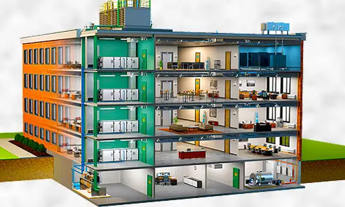
HVAC building

Due to its role in building operation, experts highly recommend regular inspection and cleaning of the commercial HVAC unit. With preventative maintenance, technicians can make repair and cleaning recommendations when necessary. A good inspection program is crucial in identifying minor leaks inside the ductwork, as minor issues quickly become severe and costly. 

By scheduling regular maintenance, you can ensure the performance and longevity of your mechanical air conditioning system. While you can rely on technicians when it comes to assessment and repair, you can do your part by installing HVAC access doors and panels

What is an HVAC Access Door?

A reliable commercial HVAC system needs to have its components functioning well to properly distribute conditioned air throughout the building. Its essential elements include the heat exchanger, blower motor, air ducts, combustion chamber, and thermostat. But how about the HVAC or duct access door? Can it be considered as part of the air conditioning unit?

The answer is a resounding yes. Access openings are without a doubt necessary in facilitating inspections, testings, repairs, and cleaning. These HVAC panels play a crucial role during maintenance services to ensure business operations — not only because they provide access but also because a good service ensures that the commercial AC unit is performing to expectations regarding safety and efficiency.

Ideally, contractors should install the HVAC panels near system components or either side of obstructions such as dampers and fans during installation. Purchasing a panel based on accurate measurements is also crucial for sufficient access to the air conditioning parts. Poorly constructed openings can harm the commercial HVAC unit in ways such as:

  • When improperly installed, the air ducts may compromise the system’s overall structural integrity.
  • Duct air leakage
  • Affect indoor air quality
  • Expose the mainframe to contamination and dust particles

No matter the panel used, it is vital to install the HVAC openings correctly and in a manner that facilitates proper closure. Therefore, it is highly ideal to hire professional contractors who have experience in physical installations.

Common Issues to Encounter if You Don’t Install HVAC Access Doors

There are many reasons why experienced contractors and technicians recommend using HVAC panels. The absence of a safe opening of the system’s mainframe and components presents many issues, particularly maintenance service providers. Without proper maintenance, your commercial air conditioner will inevitably affect its performance leading to poor air quality, among other things. Here are some possible issues you have to deal with if you choose not to install HVAC access panels.

HVAC MAINT
  • Access Limitations – Technicians’ most common problem when undertaking service maintenance or repair is limited access to HVAC components. Access limitation doesn’t primarily refer to a lack of access, but it can also refer to insufficient space due to wrong measurements or improper door installation. The building owner needs to comply with standard access regulations and the request of the maintenance service provider to enable the required work to be safely accomplished.
  • Dust and Debris Accumulation – The absence of an entry door significantly promotes dust and debris accumulation inside the air ducts and the other components. Without proper cleaning, the dust particles can readily travel through the vents and into the interior, causing allergic reactions, dust build-ups, and poor air quality. 
  • Animal Infestation – Without a good HVAC access point, your ductwork can quickly become a breeding ground for bacteria and mold growth. The molds can then attract small animals and insects, including rats, spiders, birds, and even snakes since your air passage has somehow become a thriving ecosystem for these animals. Having animals live in the ductwork can cause many issues, such as corrosion, destroyed wiring, blockage, and health issues due to animal wastes.
  • Lack of Protection – Keeping the components intact and in good condition is crucial for commercial HVAC systems to function appropriately. A duct access door offers additional protection from external elements or unauthorized access that may damage the system’s internal structure. 
  • Reduced Aesthetic Appeal – There are residential housing properties with strict aesthetic requirements. The paint and materials used during construction must be similar on all floors, and an exposed HVAC unit can be an eyesore. Concealing the device is an excellent way of staying in line with the property’s overall appearance. In addition, there are now access door options that will allow the user to paint over the cover for the unit to blend seamlessly to the surface installation.
  • Delayed Repair and Maintenance – The primary purpose of an HVAC panel is to provide access. When it comes to commercial air conditioning systems, you cannot overestimate the importance of an efficient maintenance program. Technicians will undoubtedly have difficulties identifying and isolating the damage without sufficient access. Lack of repair and maintenance can cause a landslide of problems, eventually leading to either of the HVAC issues mentioned previously. 

Takeaway

Maintaining good indoor air quality inside your building or facility is tremendously important, especially in residential units and office spaces. Turning a blind eye towards the significance of cleaning and maintaining your commercial air ducts could lead to a series of problems and, worse, the closure of your business due to negligence. Accepting that access doors have become an essential part of your commercial HVAC system is the key to a well-maintained ventilation system. Contact a licensed professional for more information, and remember to only purchase from a reputable store.


Effect of Member Configuration on the Deflection Behaviour of Trusses

Trusses are important civil engineering structures that are used in the construction of roofs of buildings, bridges, towers, stadiums, etc. The main structural feature of trusses is that they are arranged in such a manner that they form triangulated systems that resist loads mainly by developing axial forces. The axial forces in the truss members may be tensile or compressive and will lead to the global deflection of the truss.

The configuration or arrangement of the members in a roof truss significantly affects the structural behaviour of the truss. This includes the distribution of the internal stresses and deflection behaviour. Some different types of trusses have been identified based on their shape and internal members’ arrangement. Examples of such are Howe truss, Fink truss, Pratt truss, K-Truss, Warren Truss, Warren truss with verticals, Baltimore Truss, etc. In this article, the effect of member configuration on the deflection behaviour of trusses was studied.

Theoretically, the factors that affect the deflection behaviour of trusses are;

  • Member section and properties (Modulus of elasticity and cross-sectional area)
  • Individual length of members
  • Nature and magnitude of internal stresses in each member

However, in practice, it has been observed that factors such as connection details, size of holes for bolts, eccentricity of connection, etc can significantly affect the deflection value observed in roof trusses.

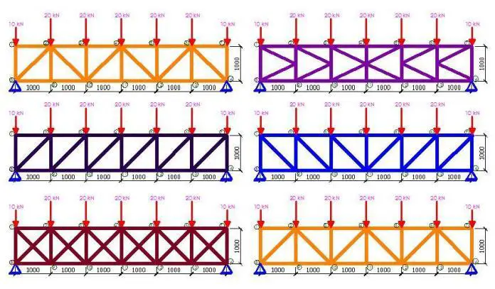
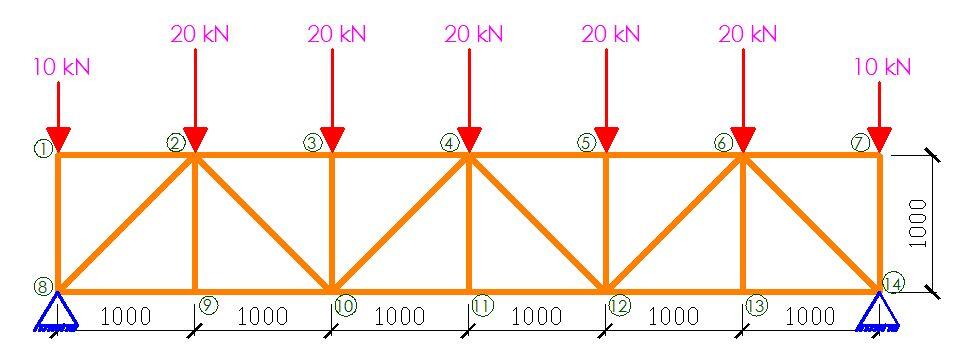
In order to achieve this, a 6m span truss was modelled on Staad Pro software and subjected to different member configurations. A constant nodal spacing of 1 m and section property of UA 90 x 90 x 10 were maintained for all the models in the study. All internal loads nodes were subjected to a concentrated load of 20 kN while the end nodes were subjected to a concentrated load of 10 kN. The typical truss configuration, loading, dimensions, and node numbering is shown below;

TYPICAL TRUSS CONFIGURATION
Figure 1: Typical loading and node numbering of the truss models

The analysis results are shown below;

Truss Type 1: Pratt Truss (Non-Parallel Diagonals)

TRUSS TYPE 1
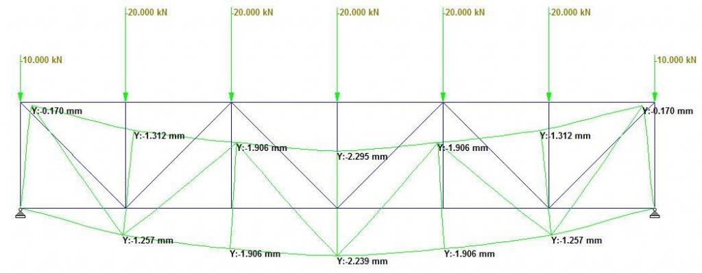
Figure 2: Configuration, loading and deflection profile of Truss Type 1

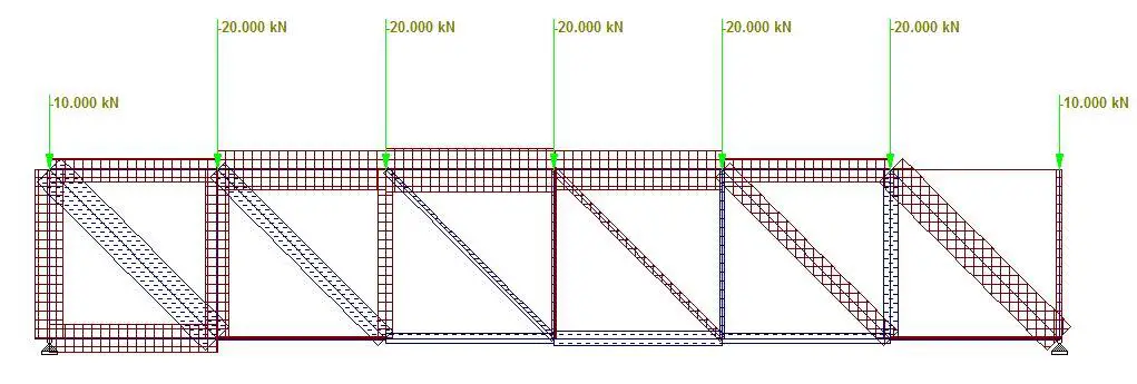
Truss Type 1 is a typical Pratt truss that is balanced in symmetry and in loading, with non-parallel diagonals in the LHS and RHS of the structure. As expected, the maximum deflection occurred at the centre with a value of 2.239 mm as shown in Figure 2. The maximum compressive forces occurred at the middle of the top chord between members 3-4 and 4-5 as shown in Figure 3. Members 3-10 and 5-10 were observed to be zero-force members. The bottom chord members between nodes 9-13 were observed to be in tension, but the entire top chord members were observed to be in compression. The general compressive to tensile member ratio was observed to be 1.5, while the web compressive to tensile member ratio was observed to be 1.16.
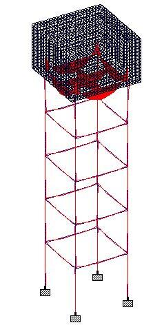
TRUSS TYPE 1 C
Figure 3: Internal stresses distribution in Truss Type 1

Truss Type 2: Parallel Flat Truss

TRUSS TYPE 2
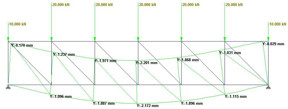
Figure 4: Configuration, loading and deflection profile of Truss Type 2

Truss Type 2 is a typical parallel flat truss comprising of verticals and diagonals that are all parallel to each other. By implication, the truss is not symmetrical in arrangement and the maximum deflection at the bottom chord occurred at the centre with a value of 2.172 mm (see Figure 4). The maximum compressive forces occurred at the top chord, while the maximum tensile forces occurred at the diagonals as shown in Figure 5. The general compressive to tensile member ratio was observed to be 2.0. In the web, the compressive to tensile member ratio was observed to be 1.6.

TRUSS TYPE 2 C
Figure 5: Internal stresses distribution in Truss Type 2

Truss Type 3: Pratt Truss (Parallel Diagonals)

TRUSS TYPE 3
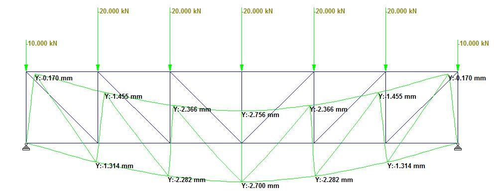
Figure 5: Configuration, loading and deflection profile of Truss Type 3

Truss Type 3 is a typical perfect Pratt truss with parallel diagonals on the LHS and RHS of the structure. The value of the maximum deflection on the bottom chord was observed to be 2.7 mm as shown in Figure 6. All the diagonals are in tension, while the verticals are in compression (see Figure 7). Furthermore, the entire top chord is in compression while the mid-span of the bottom chord is in tension. The general compression to tensile member ratio is 1.6, while the web compressive to tensile member ratio is 1.16.
TRUSS TYPE 3 C
Figure 7: Internal stresses distribution in Truss Type 3

Truss Type 4: Howe Truss

TRUSS TYPE 4
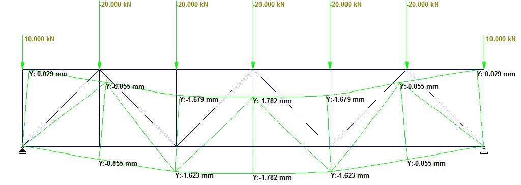
Figure 8: Configuration, loading and deflection profile of Truss Type 4

Truss type 4 is a typical Howe truss with a non-parallel diagonal arrangement. The maximum deflection on the bottom chord was observed to be 1.782 mm as shown in Figure 8. Five (5) out of the twenty-five (25) members in the truss were observed to be zero-force members (see Figure 9). Furthermore, the general compressive to tensile member ratio was observed to be 4.0, while the web compressive to tensile member ratio was observed to be to be 4.0 also.

TRUSS TYPE 4 C
Figure 9: Internal stresses distribution in Truss Type 4

Truss Type 5: Long Truss

TRUSS TYPE 5
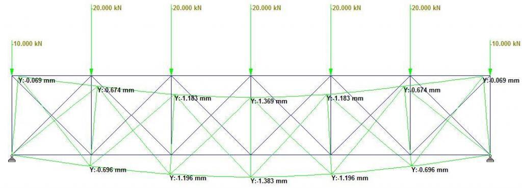
Figure 10: Configuration, loading and deflection profile of Truss Type 5

In Truss Type 5, additional internal members were introduced in the truss to form a typical Long Truss. A lower deflection value of 1.383 mm was observed at the centre of the roof truss as shown in Figure 9. This can be attributed to the additional constraints at the nodes of the trusses. The top chords are in compression (see Figure 11), and the general compressive to tensile member ratio was observed to be 1.5. In the web, a compressive to tensile member ratio of 1.11 was observed.

TRUSS TYPE 5 C
Figure 11: Internal stresses distribution in Truss Type 5

Truss Type 6: K-Truss

TRUSS TYPE 7 1
Figure 12: Configuration, loading and deflection profile of Truss Type 6

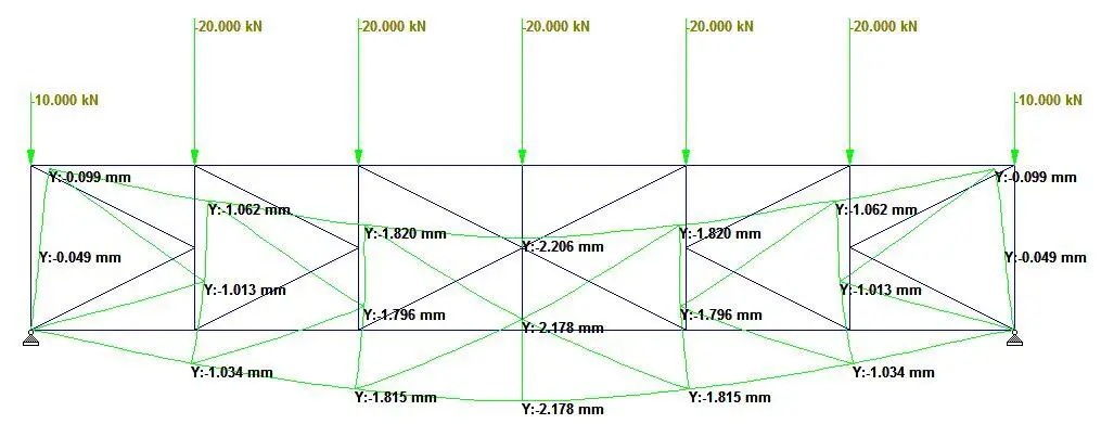
Truss type 6 is a typical K-truss. Despite having additional members, a deflection value of 2.178 mm was observed at the midspan as shown in Figure 12. Under gravity loading, a variation of axial stress distribution from compressive to tensile was observed in the vertical members (see Figure 13). A general compressive to tensile member ratio of 2.3 was observed in the truss, while the web’s compressive to tensile member ratio was 1.875.

TRUSS TYPE 7 C
Figure 13: Internal stresses distribution in Truss Type 6

Truss Type 7: Bailey Truss

TRUSS TYPE 8
Figure 14: Configuration, loading and deflection profile of Truss Type 7

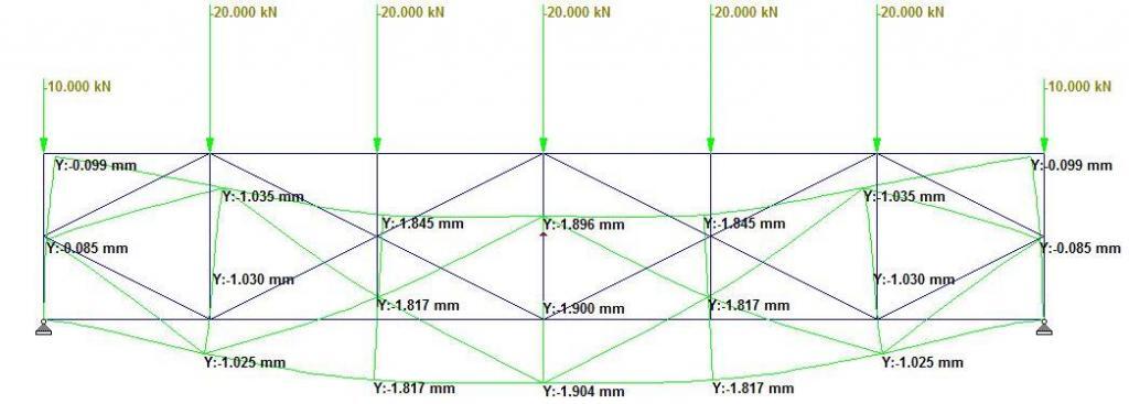
Truss type 7 is a typical Bailey Truss. The deflection at the midspan was observed to be 1.904 mm (see Figure 14). A little consideration shows that a significant number of members can be removed without affecting the behavior of the truss as shown in Figure 15. A general compressive to tensile member ratio of 2.25 was observed in the truss, while a compressive to tensile member ratio of 3 was observed in the web.

TRUSS TYPE 8 C
Figure 15: Internal stresses distribution in Truss Type 7

Truss Type 8: Bailey Truss (with K at mid-span)

TRUSS TYPE 9
Figure 16: Configuration, loading and deflection profile of Truss Type 8

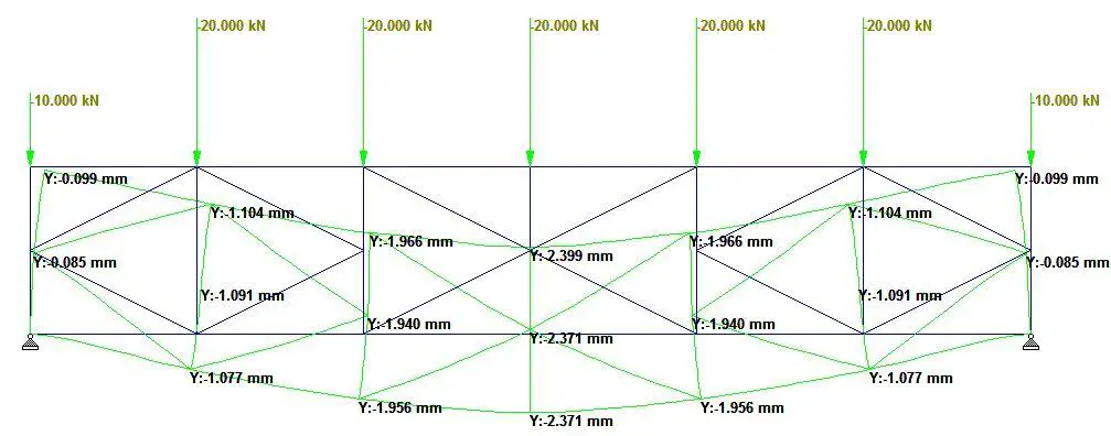
Truss Type 8 is a typical Bailey truss but with a K-configuration at the midspan. This configuration had a larger deflection than a pure K-truss or Bailey Truss arrangement. The maximum deflection observed in the truss was 2.371 mm as shown in Figure 16. A general compressive to tensile member ratio of 2.1 was observed in the truss, while a compressive to tensile member ratio of 2.83 was observed in the web (see Figure 17).

TRUSS TYPE 9 C
Figure 17: Internal stresses distribution in Truss Type 8

The summary of the findings is shown in the Table below;

Truss TypeMaximum deflection (mm)C/T ratio (general)C/T ratio (web)
Truss Type 1: Pratt Truss (Non-Parallel Diagonals)2.2391.51.16
Truss Type 2: Parallel Flat Truss2.1722.01.6
Truss Type 3: Pratt Truss (Parallel Diagonals)2.7001.61.16
Truss Type 4: Howe Truss1.7824.04.0
Truss Type 5: Long Truss1.3831.51.11
Truss Type 6: K-Truss2.1782.31.875
Truss Type 7: Bailey Truss1.9042.253.0
Truss Type 8: Bailey Truss (with K at mid-span)2.3712.12.83

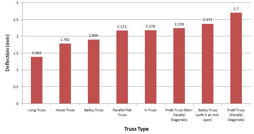
The variation of vertical deflection with type of truss is shown in Figure 18.

Effect of truss type on deflection
Figure 18: Variation of deflection (mm) with Truss Type

From the result, the lowest deflection was observed in the Long Truss (Truss Type 5) due to the additional constraints that reduced the degree of movement at the nodes. The lowest deflection value occurred at the expense of additional members and increased fabrication cost. The most economical configuration in terms of deflection can be deemed to be the Howe Truss, which offered the lowest deflection with minimal members. The ratio of the number of compressive to tensile members did not have any recognisable effect on the deflection behaviour of trusses.

Design of Reinforced Concrete Overhead Tanks

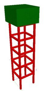
Reinforced concrete overhead tanks are water retaining structures that are placed at a height above the natural ground level. The major reason for placing the tanks at a height is to enable the water to flow under gravity to the point where they are needed. Since the tank is to be supported at a height, there is a need for a tank stand/support system, which is usually constructed of reinforced concrete, and cast monolithically with the tank shell.

The design of reinforced concrete overhead tank involves the determination of the dimensions of the tank shell to hold the desired volume of water, selection of an adequate concrete section and steel reinforcements to satisfy ultimate and serviceability limit state requirements of the tank shells, and selection of adequate column and beam sizes with the proper reinforcements to serve as the support system (tank stand).

Circular Reinforced concrete overhead tanks
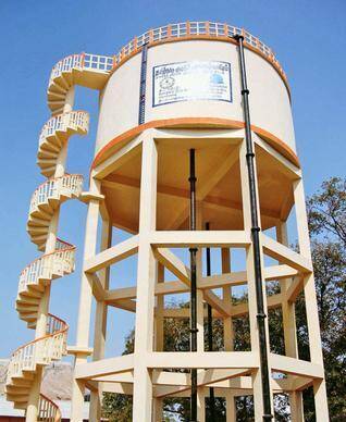
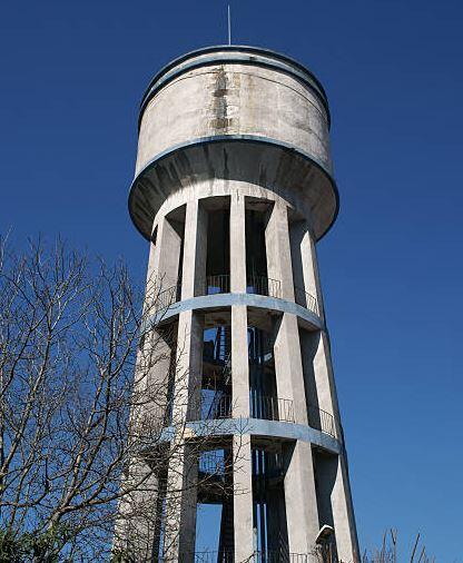
Figure 1: Circular overhead reinforced concrete water tank

The design of overhead tanks follows the same basic principles as other reinforced concrete structures, with the exception of the special attention paid to the crack width of the tank shell in order to ensure the water-tightness of the structure. In principle, the elements usually designed for in reinforced concrete overhead tanks are;

  • The tank shell
  • The beams
  • The columns
  • Other bracing systems (if any),
  • Other ancillary components like stairs and rails, and
  • The foundation

Design of the Tank Shell

The shell of the tank is the major water-holding element of the structure, which usually comprises the walls, the base, and the cover. The volume of the tank shell can be estimated by considering the water demand of the end-users of the tank, and the anticipated frequency of pumping. Furthermore, space constraints and construction challenges can also influence the final volume and shape of the tank. Typically, it is more common to calculate the volume of the tank, and then select the desired height and plan area.

The cross-section of the tank can be rectangular or circular. Circular tanks usually give more economical sections and reinforcements than rectangular tanks, even though they are more difficult to construct. Other shapes can be designed for as long the engineer can guarantee the construction feasibility and economical implication of such decisions.

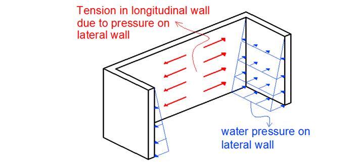
Since the tank shells are liquid containment elements, the walls and base are subjected to hydrostatic pressure from the stored water. The walls are also subjected to direct tension (for rectangular walls), and hoop tension (for circular walls). Therefore, the tank shell should have an adequate cross-section that will be able to withstand the pressure from the stored water. The design pressure is normally used to obtain the design moment, which can be used to provide the thickness of the sections and the reinforcements. The restraint condition of the tank walls influences the moment distribution (or the nature of the bending moment diagrams) which can ultimately influence the final arrangement of reinforcements.

hydrostatic pressure on tank walls
Figure 2: Typical hydrostatic pressure on the walls of the tank
Tension on tank walls
Figure 3: Typical pressure in the walls of the tank due to water pressure

In order to guarantee the water-tightness of the tank shell from a structural point of view, the crack width of the tank shell should not exceed 0.2 mm. This encompasses long and short-term cracking from flexure, shrinkage, and restraints within the concrete system. However, experience has shown that this serviceability limit state requirement usually governs the design of water retaining structures since the reinforcement required to achieve the minimum crack width is usually greater than that required to control flexure and shear.

Design of the Beams in Reinforced Concrete Overhead Tanks

Depending on the structural scheme adopted, the load from the weight of the tank and the stored water may be transferred to the supporting beams before being transferred to the columns (see Figure 4). In some cases, a flat slab concept may be adopted where the base of the tank is supported directly by columns as shown in Figure 5.

circular beam in a reservoir
Figure 4: Overhead circular tank supported on beams and columns
circular tank min
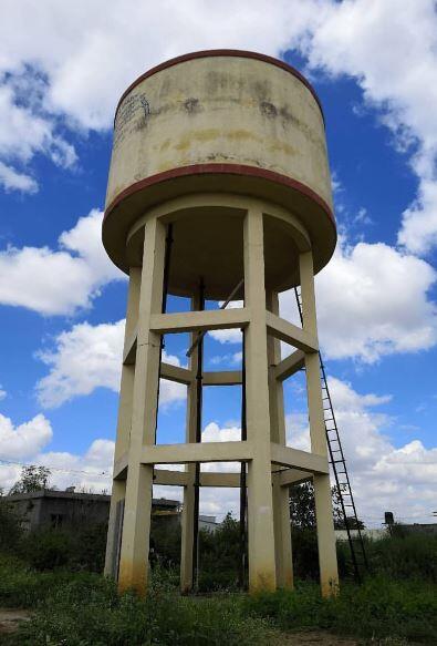
Figure 5: Overhead water tank supported on columns

However, the design concept of the beams is similar to the design concept of normal reinforced concrete beams. For the design of circular beams, it will be important to consider the effects of torsion. The procedure for the design of circular beams is readily available in literature.

Design of the columns

The design of the supporting columns in an reinforced concrete overhead tank is similar to the design of normal reinforced concrete columns. The columns will be subjected to axial force, bending, and shear from the self weight of the materials, the stored water, and wind. The size and arrangement of the columns will depend on the anticipated load from the water tank.

Furthermore, special attention must be paid to the to the concrete cover to the reinforcements in order to guarantee the durability of the structure. For the design of the columns, it will be very important to consider to consider second-order effects (p-delta) since such structures could be susceptible to such.

Design of the bracing system

More often than not, reinforced concrete overhead tanks are not provided with additional bracing systems apart from the normal beams and columns. In other words, the structure relies on the frame elements for structural stability. As a result of this, the columns should be designed as unbraced columns since they resist the horizontal loads coming to the structure.

Apart from introducing shear walls or cores, introducing diagonal or cross-bracings will likely pose significant construction and aesthetic challenges.

Design of the ancillary components

Ancillary components such as stairs and rails are provided in reinforced concrete overhead tanks for ease of movement and safety up and down the tank. Such features are important for regular inspection and maintenance of the tank after it is constructed. The stair can be made up of steel straight ladders attached to the frame, or constructed as a regular flight staircase to the top. The decision on the type of staircase will depend on the size and complexity of the water tank.

For circular water tanks, a spiral or helical staircase can be provided to wrap around the columns as shown in Figure 6.

The stairs should be firm, durable, and be able to carry the anticipated design live load. Furthermore, the rails should be able to resist direct human actions such as pulling, leaning, and mild impacts.

Design of the Foundation

The type of foundation adopted for a reinforced concrete overhead tank should depend on the height of the tank, the anticipated load, and the type of soil. On very weak and marginal soils, deep foundations such as piles may be required to send to the superstructure load to a firmer stratum.

Furthermore, for lightly loaded water tanks on a firm soil, isolated pad foundations may be provided. However, it will be in the best of the structure to ‘chain’ the entire columns together such that the foundation will behave as one unit. This will guide against the detrimental effects of differential settlement which might compromise the integrity of the superstructure. It is important to guide against secondary/indirect stresses that may cause cracks in the tank shell.

Design Example

It is desired to provide a reinforced concrete overhead water tank (not to exceed 15m high) to serve an estate of 50 households. Design the structure using relevant design standards and by making reasonable assumptions. There are no space constraints. Allowable bearing capacity of the soil = 100 kN/m2

Solution

Let us assume that each household has an average of 5 persons with a water demand of 120 litres per capita per day.

Volume of water required per day = 50 × 5 × 120 = 30000 litres = 30 m3

Making allowance for other miscellaneous uses such as the washing of cars, emergency fire fighting, etc, let us increase the volume to 35 m3.

Let the height of the tank shell (in-to-in) be 2.5 m.

Therefore the plan area of the tank = 35/2.5 = 14 m2
Let us adopt a square tank of dimensions 3.75 m × 3.75 m (Area provided = 14.06 m2)

Total volume of water anticipated (L x B x H) = 3.75 m × 3.75m × 2.5m = 35.16 m3

Initial Dimensions

Thickness of the tank shells =250 mm
Dimension of the tank shell supporting beams = 450 x 250 mm
Dimension of the bracing beams = 250 x 250 mm
Dimension of the columns = 250 x 250 mm

Therefore the centre-to-centre spacing of the square tank shell will be 4 m (such that the in-to-in dimensions will be 3.75 m).

Total weight of water = 10 kN/m3 × 35.16 m3 = 351.6 kN

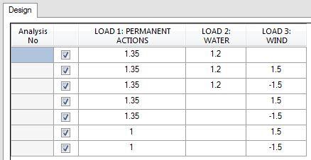
The load combinations considered in the design of the reinforced concrete overhead tank are;

LOAD COMBINATIONS

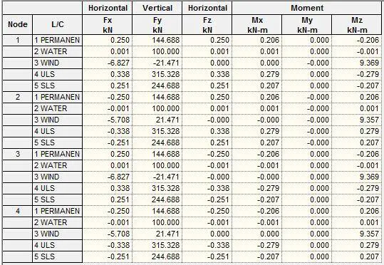
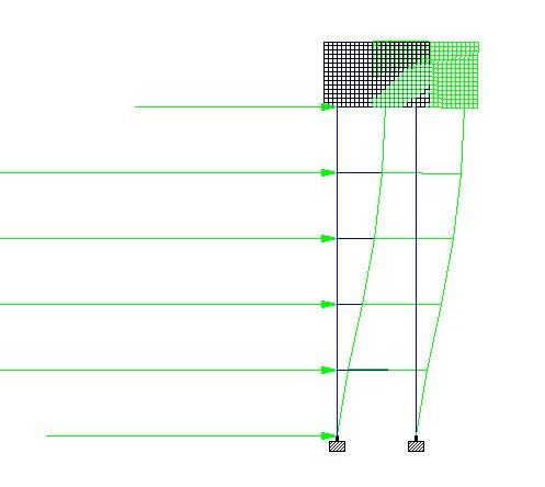
When analysed on Staad Pro, the support reactions obtained were as shown below. The maximum column axial force obtained at ultimate limit state was 315.328 kN, while the maximum service load was 244.688 kN. Therefore, with a soil bearing capacity of 100 kN/m2, a square pad footing of 1650 mm x 1650 mm should be adequate. A plinth beam beam can be introduced to chain the separate bases together.

SUMMARY OF SUPPORT REACTIONS

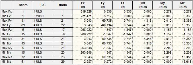
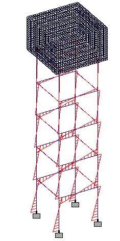
The summary of the maximum internal stresses obtained from the analysis is shown below;

Summary of internal stresses

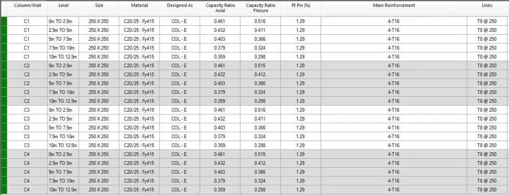
The summary of the column design results is shown below. The results show that 4-T16 as the main bars and T8@250 c/c spacing as links is sufficient for the columns.

COLUMN DESIGN OUTPUT

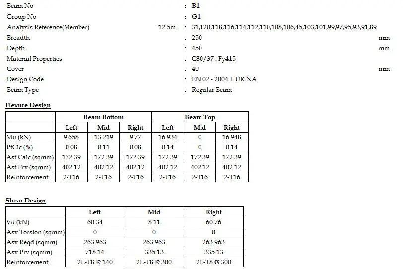
A snippet of one of the beam design results is shown below;

BEAM DESIGN 1

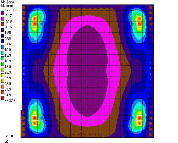
The slab analysis result is shown below;

BM AT THE BOTTOM OF TANK

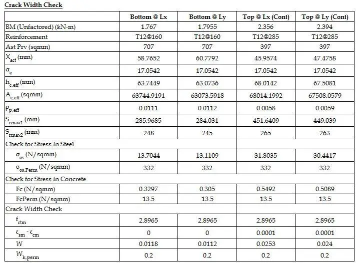
For the bottom slab of the tank shell, T12@160 c/c bottom reinforcements and T12@285 c/c Top reinforcements satisfied flexural and crackwidth requirements. See the snippet below.

DESIGN CALCULATION WITH CRACKWIDTH CHECK

Admixtures in Concrete

Materials that are added to a concrete mix aside from the basic ingredients (cement, water, and aggregates) are generally referred to as admixtures. The addition of these substances which are usually in liquid or powder form helps achieve some special effects in the concrete either in the fresh or hardened state.

In concrete, admixtures are usually categorised under ‘chemical‘ and ‘mineral‘ admixtures.

Chemical admixtures are inorganic substances that are added in concrete just before or during mixing, in addition to cement, water, and aggregate. They usually fall under categories such as superplasticizers, air-entraining admixtures, accelerating admixtures, etc.

Mineral admixtures are generally pozzolans or cement replacement materials that are usually obtained from agricultural or industrial wastes. Some examples of mineral admixtures are fly ash, rice husk ash, silica fume, etc. Mineral admixtures are usually very important in the production of green concrete, self-compacting concrete, and also help in the management of municipal wastes.

Admixtures are largely used by producers to minimize the cost of concrete construction, adjust the properties of hardened concrete, ensure the quality of concrete during mixing, transportation, placement, and curing, and overcome certain problems during concrete operations. In the United States of America, the specification for chemical admixtures is covered by ASTM C494/C494M-08. In Europe, BS EN 934-2 covers the definitions, requirements, conformity, marking, and labelling of admixtures for concrete.

The type and amount of cement used, as well as the water content, slump, mixing time, air temperature, and concrete temperatures, all influence the efficiency of an additive. Furthermore, when the water-cement ratio is reduced, more cement is added, a new type of cement is used, or the aggregate and aggregate gradation are changed, the effects are sometimes comparable to those achieved by adding admixtures.

The most common types of concrete admixtures are listed below;

(a) Admixtures that improve the performance of fresh concrete mixes

  • Plasticizers (Ordinary water-reducing admixtures)
  • Superplasticizer (High-range water reducing admixures)
  • Air entrainers
  • Pumping admixtures

(b) Admixtures that modify concrete setting time and hardening performance

  • Set retarder
  • Early Strength Agent
  • Early strength water reducing agent
  • Set accelerators
  • Pumping agent
  • Pozzolanic admixtures

(c) Admixtures that improve concrete durability

  • Gas forming admixtures
  • Air entrainers
  • Water-repellent admixture
  • Alkali-silica reactivity inhibitors

(d) Admixtures that adjust the air content of concrete

  • Gas forming admixtures
  • Air entrainers
  • Defoamer

(e) Admixtures that provide concrete special properties

  • Shrinkage reducing admixture
  • Expanding agent
  • Anti-freezing admixture
  • Curing agent
  • Coloring admixture
  • Underwater concrete anti-dispersant

(f) Admixtures that perform other special functions

  • Mold release agent
  • Damp proofing admixture
  • Concrete bacteriostatic agent
  • Anti-corrosion admixture
  • Adhesive bonding admixture

Plasticizers (Ordinary Water Reducing Admixtures)

When ordinary water reducing agent is added to concrete, it can achieve the desired slump even if the water-cement ratio is lower than normal. It normally reduces the amount of water used in the concrete mixture by around 5% to 10%. As a result, when compared to untreated concrete, concrete containing normal water-reducing admixture uses less water to create the desired consistency.

Furthermore, the water ash content of the treated concrete is low. This usually means that higher-strength concrete may be made without adding more cement to the mix. A wood grade salt (calcium or sodium) of the series is a commonly used ordinary water-reducing agent.

Superplasticizers (High-Range Water Reducing Admixtures)

Superplasticizer is a high-efficiency water-reducing admixture, that is usually classified under high-range water-reducing agent (HRWR). This admixture can lower water content by 12-30% and can be used to manufacture high slump concrete from low water-cement ratio concrete mix. The use of superplasticizers serves two purposes. One is to make high-strength concrete with a slump of 175 to 225 mm, which is used for heavily reinforced concrete structures where sufficient consolidation cannot be achieved readily by vibration; the other is to make high-strength concrete with a water/cement ratio of 0.3 to 0.4.

Water-reducing admixtures have been shown in studies to increase the workability of concrete for most types of cement. However, slump loss is a significant issue when utilizing superplasticizers in concrete. The superplasticizer effect lasts 30 to 60 minutes, depending on the brand and dosing rate, before rapidly deteriorating function. Because of the slump loss, a superplasticizer is frequently added to the concrete on the job site.

superplasticiser admixture in concrete

Naphthalenesulfonic acid formaldehyde condensate, melamine sulfonate formaldehyde condensate, polycyclic aromatic hydrocarbon sulfonate formaldehyde condensate, sulfamate series, aliphatic series, and polycarboxylic acid series are the most common forms of superplasticizers.

Gas forming admixtures

To alter the air content and apparent density of concrete, gas-forming admixtures can be used to produce a high number of confined bubbles through a chemical reaction in the concrete. This procedure can also be adopted in the production of light-weight concrete. Gas forming admixtures can improve the performance of new concrete while reducing bleeding and segregation.

Furthermore, aerated concrete provides greater freeze-thaw endurance because entrained air bubbles function as a physical buffer to prevent cracking produced by stress generated by an increase in water volume at freezing temperatures. They also improve the resistance of concrete to severe frost or freeze-thaw cycles. Almost all concrete admixtures are compatible with gas-forming admixtures.

Air-Entraining Admixtures

Air-entraining admixtures froth the mixing water, resulting in the incorporation of billions of tightly spaced air bubbles into the concrete. Water moves into the air bubbles in concrete when it freezes, releasing the pressure in the concrete. When the concrete thaws, the water in the bubbles can escape, resulting in less cracking than if air entrainment hadn’t been used.

The bubble diameter ranges from 0.02 to 1.0 mm, with the majority being less than 0.2 mm. The process is that the air-entraining agent can reduce the surface tension of the concrete by acting on the air-liquid interface, resulting in stable and fine closed pores. Small air bubbles encased in each other in the mixture can act as balls, reducing friction between the particles and improving the fluidity of the concrete. Water consumption can be lowered if the fluidity remains constant. In general, every 1% increase in air content reduces water demand by 6% to 10%.

On the other hand, the water absorption rate is reduced as a result of the reduced connecting capillaries, and the internal water pressure created by the freezing of water can be buffered, considerably enhancing frost resistance. Rosin thermopolymer resin and polyether alkyl sulfonates are the most often used air entrainers.

Pumping Admixtures

Pumping admixture is normally added to a concrete mixture that is to be pumped through a delivery conduit that is smooth, has no obstruction, has no performance segregation, and is made of good plastic material. A fluidizing agent is a type of pumping agent. It can not only considerably improve the fluidity of the combination, but it can also keep it fluid for 60 to 180 minutes, with the remaining slump not falling below the original 55 percent. It’s also not a retarder, and the retarding time shouldn’t be more than 120 minutes (except for special circumstances).

concrete pumping

Because the pumping agent is mostly made up of water-reducing agents, it is typically classified by the type of water-reducing agent used, such as lignosulfonate, naphthalene, melamine, aliphatic, sulfamate, and poly acid-based.

Set retarder

A set retarder is an additive that can extend the time it takes for concrete to set in the initial and final stages. High temperatures cause the pace of hardening to accelerate, making placement and finishing more challenging. The retarder makes the concrete workable during installation and delays the concrete’s first setting. The additive is used to slow down the chemical reaction that happens while the concrete hardens. These concrete admixtures can generally delay the rate of concrete setting and counteract the effects of high temperatures on the setting of concrete.

concrete setting

The use of curing retarding admixtures in concrete pavement construction allows for more time for repairs, lowers the expense of constructing a new concrete mixing plant on the job site, and aids in the elimination of cold joints in the concrete. Phosphoric acid, phosphate, metaphosphate, zinc salt, borax, silicofluoride, sodium sulfite, ferrous sulfate, iron, copper, zinc, cadmium sulfate, and some oxides are examples of inorganic retarders.

Set Accelerators

Concrete accelerator is an admixture that allows concrete to set and harden quickly without compromising its long-term strength. Shotcrete and fast plugging materials require it as an additive. Tunnels, basements, slopes, and other construction auxiliary structural measures such as structural reinforcement, anti-cracking, and anti-seepage engineering have all made extensive use of it.

Powder and liquid accelerators are the two types of accelerators. Accelerators with a high alkali content have a stronger detrimental impact on the concrete’s later strength, and alkali damage to human skin is also a severe concern. Currently, world-renowned businesses such as Sika, Grace, and BASF produce liquid accelerators with rather constant performance.

Water Proofing Admixture

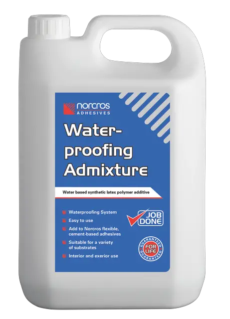
The impermeability and waterproof function of concrete can be considerably improved by a concrete waterproofing admixture, and the impermeability level can approach P25 or higher. At the same time, it has retarding, early strength, water reduction, and fracture resistance properties, as well as the ability to improve the workability of fresh mortar: it can be used in place of lime paste. It is particularly well suited to concrete for concrete roofs, water tanks and swimming pools, large-volume waterproof concrete, hydraulic concrete, waterproof mortar, and other similar applications. It is capable of totally resolving roof leaks, wall wetness, ground water seepage, and other issues.

water proofing admixtures in concrete

Colouring Admixtures

Concrete products can be colored artificially. Concrete with toner is a method of making concrete that is non-toxic, odorless, and harmless to the human body, as well as weathering and UV resistance, color stability. Red, green, yellow, black, and blue are basic colors, as well as other unique color palettes. Other colors necessary for self-preparation by the agent are simple to apply and have no effect on the mechanical qualities of concrete products.

Expanding Admixtures

An expansion agent is a type of admixture that allows concrete to expand in volume. The goal of adding an expansion agent is to compensate for the concrete’s drying shrinkage, autogenous shrinkage, and temperature deformation. This can prevent cracking and increase the concrete’s compactness and waterproof performance. Expansion agents are now being used in a growing number of building projects, including basement floor and side wall concrete, steel tube concrete, super long structure concrete, waterproof concrete projects, and so on.

Design of Underground RC Circular Water Tanks

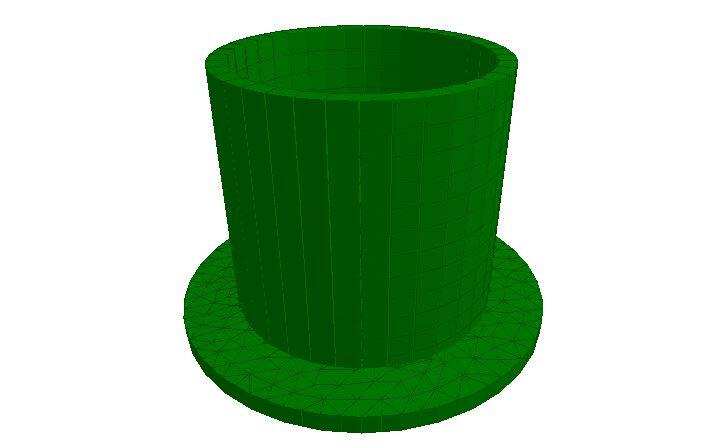
Water tanks are containment structures that are used for the storage of water for household, industrial, or commercial usage. Water tanks can be constructed in a variety of shapes such as circular (cylindrical), rectangular, oval, octagonal, etc. Furthermore, different materials such as reinforced concrete, steel, high-density plastics, reinforced polymers, etc have been successfully used in the construction of water tanks. The material to be used in the construction of water tanks must be durable, watertight, non-toxic, and strong enough to resist the hydrostatic pressure exerted by the stored water.

Circular water tanks have been shown by numerous studies to be more economical in terms of materials than square or rectangular tanks of comparable volume. However, there are more significant challenges and technicalities during the construction of circular tanks than rectangular tanks.

Water tanks can be elevated above ground level, placed on the ground surface, or buried under the ground. The design of underground circular water tanks involves the determination of the volume that will satisfy water demand requirements, and the selection of the section and reinforcements that will satisfy structural serviceability and ultimate limit state requirements.

Overhead circular water tank

Circular water tanks that are buried under the ground can be subjected to a variety of forces such as;

  • hydrostatic lateral pressure from the stored water
  • gravity vertical load due to the stored water
  • lateral earth pressure from the retained earth
  • gravity forces from the self-weight of the tank and the cover
  • surcharge forces around the tank
  • earthquake load
  • hydrostatic uplift
  • Temperature effects, and
  • other indeterminate forces and indirect actions

In order to adequately design underground circular water tanks, the effects of actions on the tank should be evaluated when the tank is empty, and when it is filled. The most critical service case should then be used in the structural design. For instance, when the tank is filled, the walls of the tank will be subjected to hydrostatic pressure from the stored water and lateral earth pressure from the retained earth. To a large extent, these pressures may neutralise each other due to their reverse directions and relatively close values, but it is often common to ignore earth pressure when assessing water tanks for ‘filled’ service conditions.

This makes sense because, during the testing or inspection of water tanks for leakage or sometime after the construction, it may be possible that the backfill earth may not be in place or removed. However, when the tank is empty, the walls will likely be subjected to earth pressure only. Therefore, it is logical to reinforce underground water retaining structures in the near face and the far face, just in case the loads are reversed.

Another important aspect in the design of reinforced concrete circular water tanks is ensuring that the section of the tank remains water-tight. This can be achieved using several methods but it is important that the crackwidth of the section remains less than 0.2 mm. Cracking is normal in reinforced concrete structures and can be caused due to direct tension or flexural stresses on the section. Early age cracking due to temperature and shrinkage of concrete can also be a problem.

The reinforcements provided, the thickness of the section, concrete cover, type of cement, type of formwork, and the temperature during casting are the main design factors that can influence the crack width of water retaining structures.

Stresses in Circular Water Tanks

Circular water tanks are designed to resist ring tensions due to the horizontal pressures of the contained liquid. The nature and distribution of internal stresses in circular water tanks depend mainly on the support conditions. According to Reynolds et al (2008), if the wall is free at the top and free-to-slide at the bottom then, when the tank is full, no vertical bending or radial shear exists in the walls of the tank. The ring tension at depth z is given by;

n = γzr

where γ is the unit weight of liquid, and r is the internal radius of the tank.

However, if the walls of the tank are connected to the base of the tank (say fixed) in such a way that no radial movement occurs, then the ring tension will be zero at the bottom of the wall. This affects the ring tensions throughout the lower part of the wall, and significant vertical bending and radial shear occur. Charts are available for the evaluation of these stresses under different types of loading and boundary conditions (see Reynolds et al, 2008; Table 2.75 – 2.77). The results gotten from the charts and finite element analysis using Staad Pro have been compared. To achieve a fixed support condition, the base of the tank will have to be expanded until the pressure distribution becomes uniform.

model of circular water tank
Finite element model of a circular water tank on Staad Pro

Alternatively, the base of the tank can be modelled as a plate on an elastic foundation. This can easily be achieved on Staad Pro software using the ‘plate mat’ or ‘elastic mat’ option as foundation/support. In this case, the property of the soil is represented using the modulus of subgrade reaction only.

According to Reynolds et al (2008), when slabs are supported on an elastic foundation, the influence on the behaviour of the tank will depend on the r/rk ratio. Where r is the radius of the base of the circular water tank and rk is the radius of the relative stiffness. The concept of the radius of relative stiffness rk was developed by Westergaard and is given by the Equation below;

rk = [Ech3/12(1 – v2)ks]0.25

where Ec, is the short-term modulus of elasticity of the concrete, h is the slab thickness, ks is the modulus of subgrade reaction, and v is the Poisson’s ratio.

Worked Example(s)

A circular water tank 3.8 m deep with a mean radius of 2 m is open at the top and fixed at the bottom. Determine, due to internal hydrostatic loading and lateral earth pressure, the maximum service values for circumferential tension, vertical moment, and radial shear in the walls of the tank. The walls of the tank are 300 mm thick, and the water level is taken to the top of the wall.

Solution

From Table 2.75 of Reynolds et al (2008);
lz2/2rh = 3.82/(2 × 2 × 0.3) = 12.03

At z/lz = 0.7; αn1 = 0.633
αm1 = 0.0026 and -0.0104
αv1 = 0.145

Hoop tension n = αn1γlzr = 0.633 × 10 × 3.8 × 2 = 48.108 kN/m
Vertical moment (span) m = αm1γlz3 = 0.0026 × 10 × 3.83 = 1.427 kNm/m
Vertical moment (edge/support) m = αm1γlz3 = -0.0104 × 10 × 3.83 = -5.706 kNm/m
Radial shear v = αv1γlz2 = 0.145 × 10 × 3.82 = 20.983 kN/m

Load Case 2
In the same way, if we assume that the tank is buried under the ground and backfilled with sand of angle of shearing resistance 30° and unit weight of 19 kN/m2. Then the coefficient of earth pressure at rest using Rankine’s theory is given by;

Ko = (1 – sin 30°)= 0.5

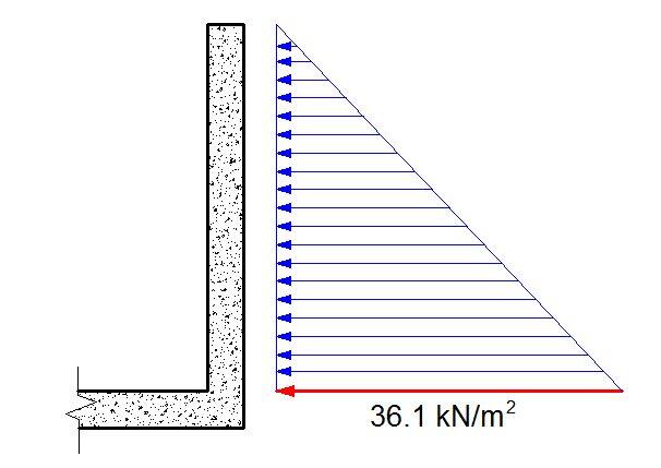
The maximum lateral earth pressure at the base of the wall will be given by;
p = koγz = 0.5 × 19 × 3.8 = 36.1 kN/m2

However, for the purpose of the formula to be used in the analysis, the unit weight of the material to be plugged into the equation can be represented as koγ = 9.5 kN/m3

external pressure on tank wall

In the same vein, we calculate;

Hoop compression n = αn1γlzr = 0.633 × 9.5 × 3.8 × 2 = 45.7 kN/m
Vertical moment (span) m = αm1γlz3 = 0.0026 × 9.5 × 3.83 = 1.355 kNm/m
Vertical moment (edge/support) m = αm1γlz3 = -0.0104 × 9.5 × 3.83 = -5.421 kNm/m
Radial shear v = αv1γlz2 = 0.145 × 9.5 × 3.82 = 19.891 kN/m

In the design of the walls of the tank, the hoop tension must be resisted entirely by the ring reinforcements. When considering the hoop compression from the retained earth, the contribution of the concrete and steel can be considered (just like in the design of columns). It is typical to design the section for hoop tension and check for its adequacy in hoop compression.

The vertical reinforcements in each face of the wall must be able to resist the vertical moments due to the water pressure and the retained earth. This applies also to the span bending moments. Typically, the vertical reinforcements can be reduced accordingly as the wall goes higher. The quantity of reinforcement to be provided is also heavily influenced by cracking requirements.

In summary, the design of circular tanks is an interesting endeavour that can be carried out using hand calculations or computer software. Feel free to contribute to knowledge here.

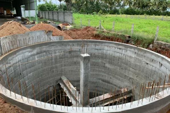
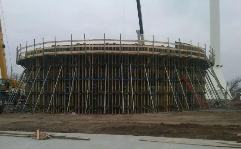
construction of circular water tank


Design of Slurry Cut-Off Walls | Slurry Trenches

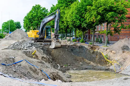
Slurry cut-off walls or slurry trenches are excavations that are made under the ground and filled with engineered slurries for the purpose of preventing the movement of groundwater into an excavation or construction area. Apart from acting as barriers to groundwater movement, slurry walls can also be used as barriers to the flow of leachate or contaminated groundwater. They can also be used to prevent the migration of gases into an area in a soil formation.

Slurry cut-off walls have been used for a long time in the control of groundwater during construction. In principle, engineered slurries are placed into a narrow excavation that forms the boundary of the area that needs to be barricaded from groundwater flow. The slurry will exert a hydrostatic pressure on the face of the excavation which will keep it stable from collapse while at the same time, prevent the movement of groundwater into the area of interest. Slurry cut-off walls are applicable to all kinds of soils but are more applicable to sandy soil deposits where the coefficient of permeability is high. Sandy soils also have more potential for collapse when excavations in it are unsupported.

Excavations for slurry trenches can be carried out using hoe excavators and can extend very deep to the impermeable stratum on the soil profile. Therefore, the construction will require adequate planning for workspace, safety, and operation of heavy construction equipment.

Bentonite slurry is the most commonly used material for filling slurry trenches. Bentonite slurry is formed by mixing bentonite clay with water, after which the colloidal mixture is pumped into the excavation. As a result, no additional shoring or bracing is required in slurry cut-off walls (see design of braced cuts).

One of the requirements of slurry trenches is that the lateral pressure exerted by the slurry on the excavation face must be equal to or greater than the lateral pressure from the soil and ground water. The properties of the slurry which influence the design of slurry trench walls are;

  • Density of the slurry
  • Gel strength (thixotropy) of the slurry
  • Viscosity of the slurry
  • pH of the slurry

The aim of this article is to show how to determine the required minimum density of slurry that will ensure the lateral stability of an excavation using a worked example.

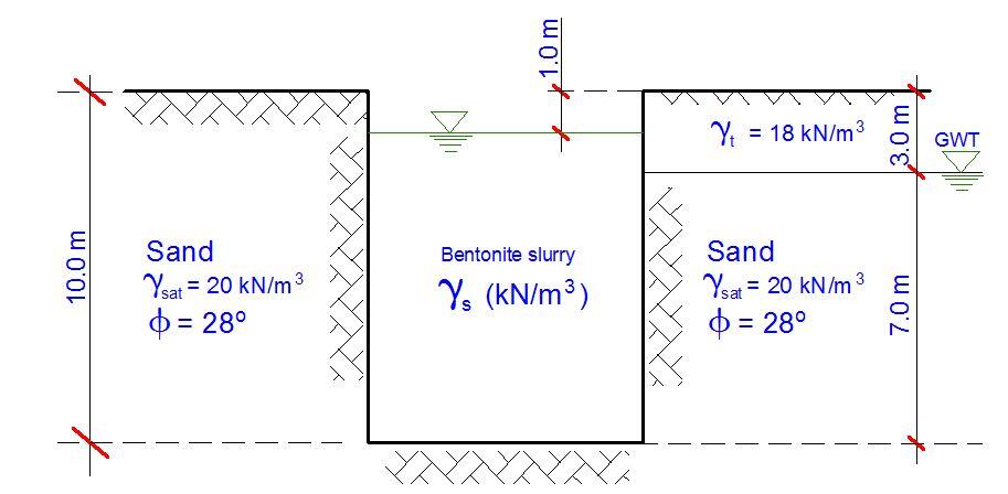
Solved Problem

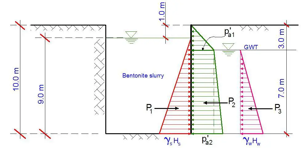
slurry trench problems 1


For the slurry cut-off wall shown above, calculate the minimum density of the slurry in the trench to prevent the wall of the excavation from sliding.

Solution
The solution to this problem is based on the principle of lateral earth pressure. The lateral pressure exerted by the slurry must be equal to or greater than the lateral earth and groundwater pressure at the face of the excavation. The free-body diagram of the pressures are shown below;

lateral pressure on slurry cut-off walls

For stability of the excavation;

P1 = P2 + P3

Using Rankine’s earth pressure theory, the coefficient of active earth pressure is given by;

kA = (1 – sinΦ)/(1 + sinΦ) = (1 – sin 28)/(1 + sin 28) = 0.361
P1 = ½γsHs2 = (0.5 × γs × 92) = 40.5γs
P3 = ½γwHw2 = (0.5 × 9.81 × 72) = 240.345 kN/m

p’a1 = kaγth1 = 0.361 × 18 × 3 = 19.494 kN/m2
p’a2 = kath1 + (γsat – γw)hw] = 0.361[18 × 3 + (20 – 9.81) × 7] = 45.244 kN/m2

P2 = ½(p’a1)h1 + ½(p’a1 + p’a2)hw = (0.5 × 19.494 × 3) + 0.5( 19.494 + 45.244) × 7 = 29.241 + 226.583 = 255.824 kN/m

P1 = P2 + P3
40.5γs = 255.824 + 240.345
On solving;
γs = 12.25 kN/m3

Therefore, among other factors the slurry must have a minimum density of 12.25 kN/m3.

Production of Bioreceptive Concrete

Bioreceptivity is defined as the ability of a material to be colonised by one or more groups of living organisms without necessarily undergoing biodeterioration. By implication, a bioreceptive concrete should support and sustain biological growth without experiencing loss in strength or durability. The use of bioreceptive facades has been suggested as a promising cost-effective solution for combating the loss of green areas due to urbanisation.

In nature, bioreceptive surfaces are characterised by the presence of several stress-tolerant micro-organisms such as bacteria, algae, fungi, lichen, and mosses, which together will form biofilms. According to researchers from the Delft University of Technology, Netherlands, these micro-organisms despite being stress-tolerant still require certain requirements to be met in the substrate before they can survive and thrive. The study was published by the Journal of Building Engineering (Elsevier).

The material characteristics that have been commonly observed to improve bioreceptivity are high capillary water content, high surface roughness, abrasion pH level less than 10, high open porosity, etc. The use of phosphorus has also been been observed to improve to bioreceptivity of concrete by providing nutrients for biological growth. Numerous researches are still ongoing on how to improve bioreceptivity especially in materials like concrete which is the most commonly used building material.

bioreceptive concrete

Concrete has properties and features that are close to that of natural stones on which biofilms can form. However, normal concrete has limited or no capacity to support biological growth. Therefore, for concrete to be made bioreceptive, it has to be designed or developed by modifying or adding to its constituent properties. Therefore, the challenge of creating eco-friendly facades using bioreceptive concrete lies in the material itself. This has been the objective of numerous research works on bioreceptive concrete.

As highlighted earlier, one of the reported challenges of creating bioreceptive concrete is reducing the pH of the concrete. Some research works have used either magnesium phosphate cement or carbonation chambers to reduce the pH of their concrete samples. However, this has always proved to be an expensive solution due to the cost of magnesium phosphate. Researchers from Delft University of Technology however used the addition of blastfurnace slag to ordinary portland cement to reduce the pH. According to them, this a common additive in the concrete industry which reduces the pH of the resulting concrete through increased carbonation.

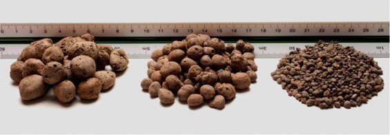
Furthermore, the use of surface retarders was used to achieve increased surface roughness, which the authors described as a commonly applied non-labour intensive procedure. Open porosity and high capillary water content was achieved by increasing the water to cement ratio of the concrete, such that when the hydration reaction is complete, excess pore water will evaporate thereby leaving more voids in the concrete. However, it is important to limit the water-cement ratio to 0.6 in order to not to have a compromised concrete mix in terms of strength. Additionally, crushed expanded clay was used to replace the large diameter aggregates in order to improve the porosity of the mix.

expanded clay aggregate
Expanded clay aggregate

Instead of using phosphorus, the researchers investigated the use of cow bone ash which has been applied in several research works as a partial replacement for cement in concrete production. Cow bone ash contains calcium oxide (CaO) and phosphorus pentoxide (P2O5). The aim of the research work was to investigate the effects of these modifying factors on the bioreceptivity of concrete.

From the research findings, the authors concluded that use of surface retarder increased the bioreceptivity of the concrete likely by increasing the available surface area and by removing the hydrophobic top layer of the concrete. Furthermore, the addition of cow bone ash increased the bioreceptivity of the concrete by making more nutrients (phosphorus) available within the substrate. Crushed expanded clay increased the bioreceptivity of concrete by making the concrete more porous and by a being a bioreceptive material itself.

However, increasing the water to cement ratio did not have a significant effect on the bioreceptivity of the concrete. The research further suggested that it is not necessary to reduce the pH of the concrete to less than 10, since samples with pH more than 10 showed moderate to high biological growth.


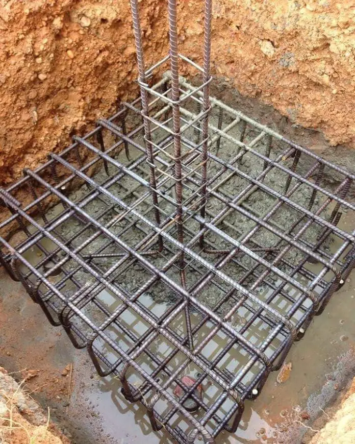
Question of the Day | 01-10-2021

Is there any practical loading condition or analysis of isolated column base (pad foundation) that will require the provision of top and bottom reinforcement as shown in the picture above?

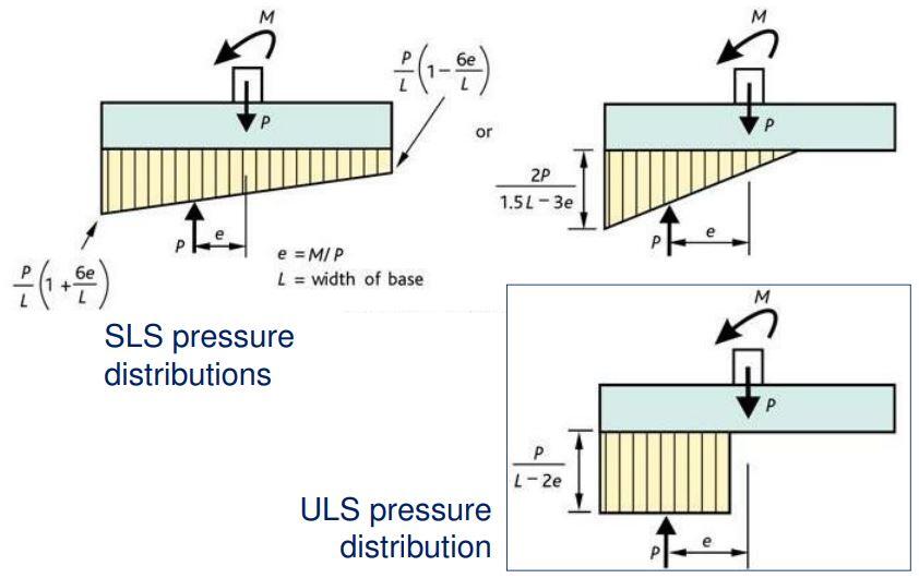
When rigid pad foundations are subjected to eccentric loading, the base pressure distribution becomes either trapezoidal or triangular instead of uniform (rectangular). Any condition that leads to negative pressure (tension) in the soil usually calls for a geometric redesign of the column base size.

pressure distribution of pad foundations

Under which condition can top and bottom reinforcement be required in an isolated pad footing then? Let us know in the comment section.

How to Estimate the Engineering Properties of Fine-Grained Soils

When a soil sample contains a majority of particles (by weight) less than 0.063 mm in size, and stick together when wet, such soil can be described as fine-grained soil. Fine-grained soils usually contain silt and clay particles which can easily be remoulded. Silt particles are between 0.002 mm and 0.063 mm in size while clay particles are smaller than 0.002 mm.

The recommended process for establishing the engineering properties of soils is to carry out as accurately as possible, laboratory or field tests on the soil sample. The tests usually carried out on soils consist of the index properties tests, strength tests, and permeability tests.

Index property tests are usually used for the purpose of soil classification and includes particle size distribution analysis, Atterberg limits tests, linear shrinkage, specific gravity, free swell, etc. These tests are carried out on disturbed soil samples. However, strength tests can include compressibility tests (oedometer tests), shear strength tests, unconfined compression strength tests, CBR, etc. One of the most important tests is the shear strength tests which is used to obtain the angle of internal friction and cohesion of the soil.

According to BS 8004:2015, the following should be considered as minimum when establishing the values of parameters for fine-grained soils:

  • the items listed in BS EN 1997-1:2004, 2.4.3(5);
  • pre-existing slip surfaces;
  • desscation; and
  • any changes in stress state either induced by construction or resulting from the final design condition.

When the plasticity index of a clay soil is greater than 20%, it might exhibit angle of internal friction (angle of shearing resistance) that is considerably lower than that observed at the critical state, if their particles become fully aligned with one another. In BS 8004:2015, this phenomenon is called “sliding shear” in order to distinguish it from from “rolling shear” which is observed in other soils with plasticity index less than 20%. The angle of shearing resistance exhibited during sliding shear is called the “residual angle of shearing resistance“.

Estimation of Undrained Shear Strength of Fine-Grained Soils

According to clause 4.3.1.4.5 of BS 5400:2015, the undrained shear strength of a fine-grained soil may be estimated from the relationship below in the absence of reliable test data:

cu,k/p’v = k1Rok2 = k1(p’v,max/p’v)k2

Where:
cu,k = characteristic underained shear strength
p’v = effective overburden pressure
p’v,max = the maximum overburden pressure that the soil has been previously subjected to;
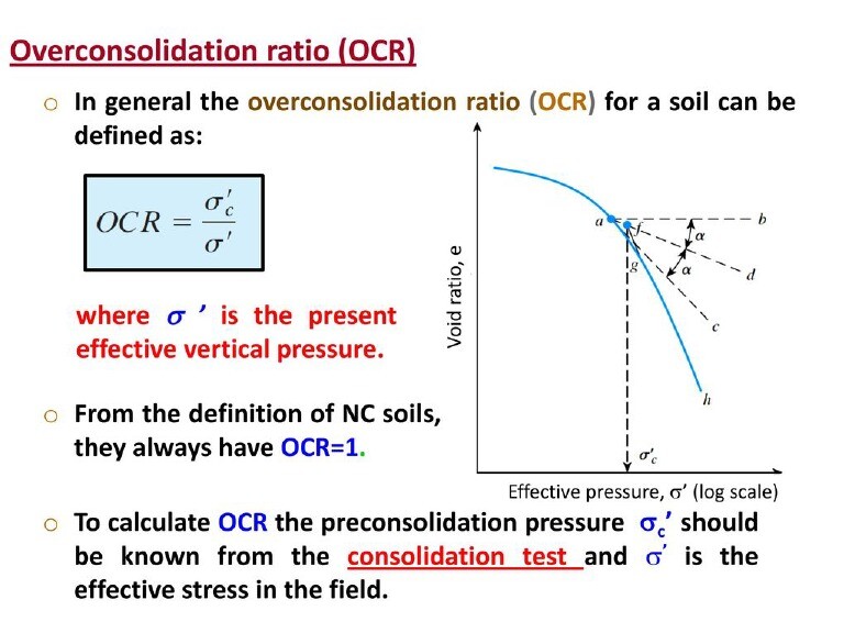
Ro = overconsolidation ratio

k1 and k2 are constants. In the absence of reliable test data, k1 may be taken as 0.23 ± 0.04, while k2 may be taken as 0.8. Furthermore, it should be noted that cu,k/p’v is not a constant but varies with depth.

Overconsolidation ratio of fine-grained soil
Understanding the meaning of overconsolidation ratio

Obviously, consolidation test results should be available before the relationship can be applied. When determining the characteristic undrained strength of high strength fine-grained soils, due allowance should be made for:

  • the detrimental effect of any sand or silt partings containing free groundwater
  • the influence of sampling
  • the influence of the method of testing; and
  • likely softening on excavation

Estimation of Constant Volume Angle of Shearing Resistance of Fine-Grained Soils

In the absence of reliable test data, the characteristic constant volume (ie the angle of internal friction at the critical state) effective angle of shearing resistance φ’cv,k may be estimated from;

φ’cv,k = (42° – 12.5log10Ip) for 5% ≤ Ip ≤ 100%

where:
Ip is the plasticity index of the soil (entered as a %)

The values of φ’cv,k for different plasticity index values based on the expression above is shown in Table 1:

Plasticity Index Ip (%)Characteristic constant volume angle of shearing resistance φ’cv,k (Degrees °)
1527
3024
5021
8018

It should be noted that the effective cohesion at the critical state should be taken as zero (the characteristic constant volume effective cohesion = 0).

The peak effective angle of shearing resistance φ’pk may be related to the constant volume effective abgle of shearing resistance φ’cv by:

φ’pk = φ’cv + φ’dil

Where;
φ’cv is the constant volume effective abgle of shearing resistance
φ’dil is the contribution to φ’pk from soil dilatancy

Column Formwork: Alternatives in Design and Construction

Formwork is an important aspect of the construction of reinforced concrete construction. Column formwork design and construction have evolved over the years with so many alternatives in terms of material selection and installation procedures. Reinforced concrete columns are vertical compression members whose depth to thickness ratio is less than 4, otherwise, it should be described as a shear wall. ACI 318 defined a column as a member with a ratio of height-to-least-lateral-dimension exceeding 3 and is used primarily to support axial compressive load.

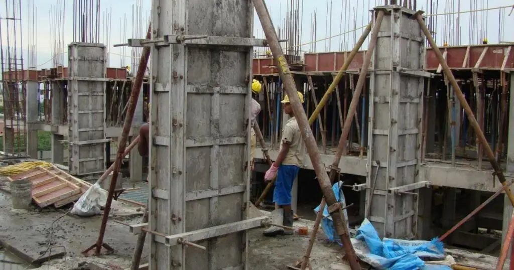
Traditionally, column formworks are entirely constructed from timber planks or plywood with studs, wales, and struts for support. In this case, the timber planks must be sawn to the size of the column with a proper allowance for edge laps and/or closure. The planks are usually joined together through nailing. If the columns in the building are not of the same dimensions, reuse of the column formworks becomes difficult if not impossible. Furthermore, during dismantling, the formworks are prone to damage.

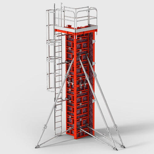
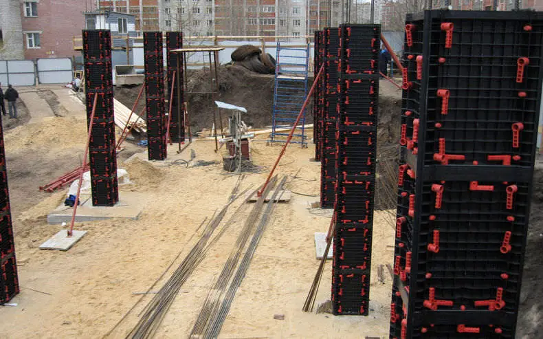
The modern column formwork systems available right now are modular in nature and allow quick assembly and erection on-site while minimising labour and crane time. They are available in steel, timber panels, plastic, aluminium, and even cardboard (not reusable but recycled) and have a variety of internal face surfaces depending on the concrete finish required. Innovations have led to adjustable, reusable column forms which can be clamped on-site to give different column sizes.

peri formwork
Modern composite column formwork (Peri)

A composite system consisting of wooden panels and steel framing is available and offers the advantage of being lightweight when compared to formwork systems that are made of steel. In constructions works where cranes are not available, steel column formworks have been found to be unattractive because of weight. However, modern modular plastic formworks are available which offer lightweight, flexible, and very good re-use potentials to contractors.

Steel column formwork
plastic column formwork
Plastic modular column formwork

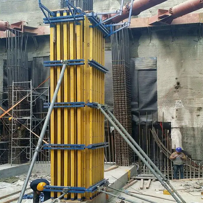
Column formworks can also be constructed locally using 20 mm thick plywood, timber studs (or H-beams/Joists), and clamps. Different types of clamps are available and can be constructed locally by welding threaded rods to Y16mm reinforcement bars as shown in the Figure below. Off-cuts of Y25mm bars or strong timber members can be used to hold the column panels and clamps in place. The advantage of this system is the fairly high level of re-use, but the setup and clamping process is more tedious when compared with other types of modular formworks.

column formwork 1
column formwork 3

Construction Sequence of Column Formworks

The basic construction sequence using the modular type of column formwork is as follows:

  1. The column setting out is done as appropriate and the rebars installed.
  2. The concrete kicker of about 75mm thick is cast in the appropriate location
  3. The column forms are assembled and positioned to enclose the column reinforcement.
  4. The column formworks are then positively restrained and braced using props.
  5. Proper checks are done to ensure that columns are perfectly straight and well-aligned before concreting commences.
  6. Concreting is done with minimum disruption of the formwork position.
  7. Column formwork is checked for verticality and alignment after the concreting
  8. Once the concrete has hardened sufficiently the formwork is stripped and moved to the next position manually or by crane. Disposable forms may be left in place for an extended period to aid curing and strength gain of the concrete before removal.

Other Considerations in Column Formwork Installation

  • The column forms are designed for specific maximum concrete pressures. The concrete placement rates have to be adjusted to keep the concrete pressure within the specified limits.
  • The assembled formwork has to be restrained at the base properly to avoid displacement, and grout loss during concreting.
  • In some metal systems, the push/pull props used to stabilise the column formwork are integral.
  • Some systems can be moved on wheels rather than by crane.
  • The formwork and access equipment can be moved in a single operation with some systems
  • Some metal systems can be easily adjusted in plan size and height (by stacking additional panels on top of each other).

Lateral Pressure on Column Formworks

One of the most important parameters in the design of vertical formworks is the lateral pressure exerted on the face of the formwork by the fresh concrete. The lower the plastic viscosity and yield stress of the fresh concrete the more the original lateral pressure will be. However, faster rates of hardening will lead to faster rates of decay in the lateral pressure. Lateral pressure occurs only as long as the concrete is in a fresh state.

The magnitude of pressure exerted by fresh concrete depends on the following;

  1. The depth of fresh concrete from the top (free surface) to the depth under consideration.
  2. The unit weight of the concrete (ρc)
  3. The rate of concrete placement (R)
  4. Temperature of concrete during placement (T)
  5. Unit weight coefficient (Cρ) which depends on the unit weight of the concrete
  6. Chemistry coefficient (Cc) which depends on the type of cementitious materials
  7. Method of concrete placement

According to the ACI Committee 347, the formula for calculating the maximum lateral pressure exerted by fresh concrete on vertical column formworks is;

Pmax = CρCc[7.2 + 785R/(T + 17.8)]

The unit weight coefficient Cρ can be calculated using the Table below;

Density of concreteUnit weight coefficient (Cρ )
Less than 2240 kg/m3 Cρ = 0.5[1 + ρc/2320] but not less than 0.8
2240 – 2400 kg/m3 Cρ = 1.0
More than 2400 kg/m3 Cρ = ρc /2320

The value of the chemistry coefficient Cc can be picked from the Table below;

Type of cementChemistry Coefficient Cc
Types I, II, and III without retarders1.0
Types I, II, and III with retarders 1.2
Other types or blends containing less than 70% slag or 40% fly ash without retarders 1.2
Other types or blends containing less than 70% slag or 40% fly ash with retarders 1.4
Other types or blends containing more than 70% slag or 40% fly ash 1.4

In the UK, the formula for calculating the pressure on formworks according to CIRIA Report 108 is given by the equation below, which must not be greater than the hydrostatic pressure.

Pmax = [C1√R + C2K √(H1 – C1√R)]γ

Where:

Pmax = Maximum lateral pressure against formwork (kPa)
R = Rate of placement (m/h)
C1 = Coefficient for the size and shape of the formwork (1 for walls).
C2 = Coefficient for the constituent materials of the concrete (0.3 – 0.6).
γ = Specific weight of concrete (kN/m3).
H1 = Vertical form height (m).
K = Temperature coefficient K = (36/T + 16)2

Steps in the Design of Column Formwork

The following steps can be adopted in the designing of column formworks;

  1. Determine all the necessary design parameters such as the dimensions of the column, type of concrete, rate of placement, and temperature of placement.
  2. Calculate the design lateral pressure from the fresh concrete, and draw the lateral pressure distribution diagram.
  3. Select suitable plywood (with known mechanical properties) for the sheathing
  4. Select a trial timber backing section (with known mechanical properties) and assume a trial spacing
  5. Determine the bending moment, shear, and deflection of the plywood using the design pressure distribution diagram.
  6. Determine the bending moment and shear on the backing timbers and compare it with the permissible stress of the section.
  7. Design the steel/timber yokes and tie rods by checking the stresses on them. Compare this with the allowable stresses on the members.