8.7 C
New York
Sunday, June 8, 2025
Home Blog Page 15

Groundwater Control: Exclusion Techniques

Many civil engineering projects usually involve excavating into water-bearing soil formations. Before beginning such excavations, the proper system(s) for managing and controlling groundwater and surface water run-off should be planned. This can only be done in practice if you are aware of the ground and groundwater conditions you are likely to face through site investigation data.

It is necessary to take precautions to manage groundwater flows and pore water pressures in water-bearing soils in order to prevent problematic circumstances during excavation and construction. Effective management of surface water runoff is also necessary. Understanding the potential effects of an excavation can help determine which groundwater control measures are required to assure stability.

There are three groups of methods available for temporary works control of groundwater:

(a) Lowering groundwater levels in construction by means of water abstraction, in other words – groundwater lowering or dewatering.
(b) Exclusion of groundwater inflow to the area of construction by some form of very low permeability cut-off wall or barrier (e.g. sheet-piling, diaphragm walls, artificial ground freezing).
(c) Application of fluid pressure in confined chambers such as tunnels, shafts and caissons to counterbalance groundwater pressures (e.g. compressed air, earth pressure balance tunnel boring machines).

Groundwater Control Techniques

Techniques for the control of groundwater can be divided into two principal types:

(a) Those that exclude water from the excavation (known as exclusion techniques)
(b) Those that deal with groundwater by pumping (known as dewatering techniques)

Exclusion Methods of groundwater control

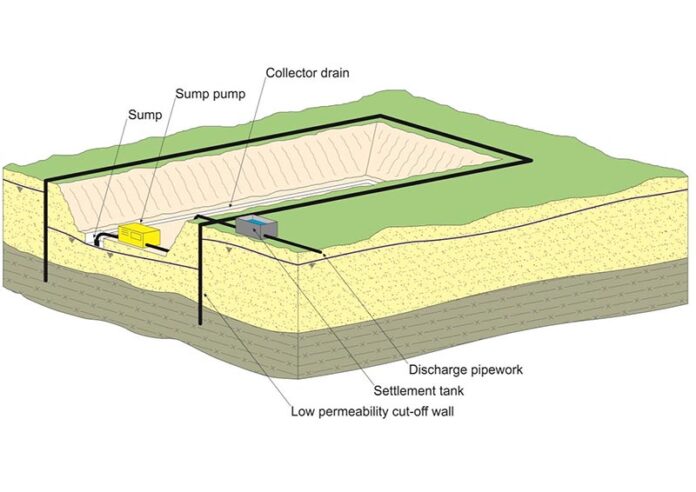
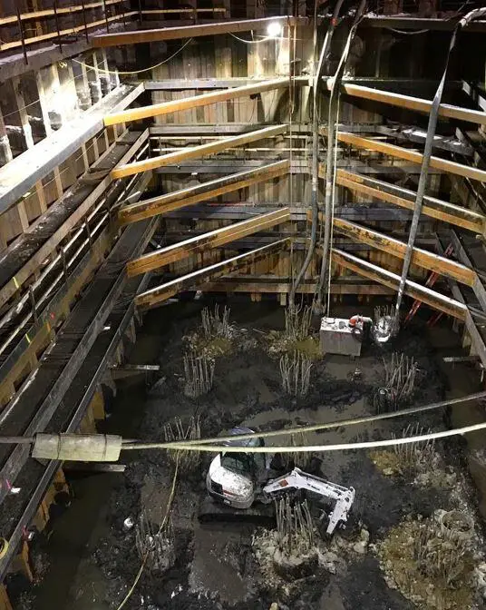
The aim of groundwater control by exclusion is to prevent groundwater from entering the working area. Creating a physically impermeable cut-off wall or barrier around the perimeter of the excavation to keep groundwater out is one of the most widely used exclusion methods. The cut-off often produces a basal seal for the excavation by penetrating vertically down to a very low permeability stratum.

image 7
Exclusion method of groundwater control

The depth and make-up of any underlying permeable stratum have a significant impact on the costs and viability of constructing a physical cut-off wall. Base instability is possible when upward seepage occurs beneath the base of the cut-off wall due to the lack of or presence of a sufficient very low permeability layer. In these situations, dewatering techniques and exclusion techniques may be combined.

As an alternative, a horizontal barrier or “floor” might be formed adjacent to the cut-off structure to stop vertical seepage. Although it is not common, horizontal barriers have been built utilizing techniques such jet grouting, mix-in-place grouting, and artificial ground freezing.

A portion of the groundwater will become trapped inside the working area if a complete physical cut-off is established. In order to move further with the project, this must be removed, either by sump pumping during excavation or by pumping from wells or wellpoints beforehand.

The capacity of the exclusion technique to enable work to be carried out below the groundwater level with little impact on groundwater levels outside the site is one of its attractive features. This ensures that any groundwater-lowering problems are prevented. Exclusion techniques are frequently employed instead of dewatering techniques, especially in metropolitan areas, to reduce the danger of settlement damage brought on by reducing groundwater levels.

However, it is crucial to remember that practically all walls will leak to some degree when considering the use of the exclusion technique to prevent groundwater level from dropping in areas beyond the site. Particularly vulnerable to leakage are any joints (between columns, panels, piles, etc.) left behind from the installation process.

Several issues can arise if groundwater leaks through cut-offs into the excavation or work area:

(i) The seepages may hinder site operations during construction, necessitating the deployment of sump pumps or surface water management techniques to keep the working area dry.
(ii) The risk of settlement or other negative impacts may result from the leaking into the excavation being severe enough to locally lower groundwater levels outside the site.
(iii) If the cut-offs are a permanent construction, like the walls of a deep basement, even tiny seepages over time will be ugly and could interfere with any architectural finishes that have been applied to the walls.

Grouting or other treatments can frequently be used to address the major seepages that cause issues (i) and (ii). On the other hand, it might be quite challenging to stop or stop the little seepages of (iii). Costs significantly increase if a completely dry or leak-proof construction is required. If cut-off walls are going to be included in the permanent works, this is something that needs to be taken into account.

The techniques used in groundwater exclusion are listed below;

Steel Sheet Piling

In this groundwater control technique, steel sheet piles are driven into the soil to form a barrier against the intrusion of groundwater into the construction area. This is one of the most prominent techniques used in the construction of cofferdams. This technique is applicable to most open soils, however, it can be challenging when obstructions such as rock boulders are encountered.
cofferdam in the world

Steel sheet pile walls may be installed to form permanent cut-off, or used as temporary cut-off with piles removed at the end of construction. They offer the advantage of rapid installation and are relatively cheap. Additionally, they can support the sides of the excavation with suitable propping.

The disadvantages are that the seal may not be perfect, especially if obstructions are encountered. Vibration and noise of driving may be unacceptable on some sites, but ‘silent’ methods are available.

Vibrated beam wall

In this method, a grout injection nozzle is driven into a specially made wide flange beam section using a vibratory driver-extractor that is attached to the beam’s base. A self-hardening slurry is injected into the ground with the designed beam while it is vibrated into the ground to act as a lubricant.

When the beam is withdrawn, the extracted beam element leaves a minimum of a 4 to 6-inch panel that is filled with the self-hardening slurry. A continuous cutoff wall is created by the consecutive beam element insertions and the overlapping of the earlier beam insertions.
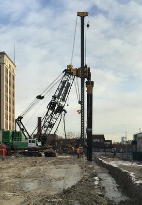
vibrated beam cutoff wall
Vibrated beam cut-off wall

The Vibrating Beam construction technology enables operations in small spaces with little room for above-ground mixing or staging. This method also decreases soil disposal costs, which can be expensive when dealing with hazardous locations, as less excavation is needed. Permeabilities in the range of 10-8 cm/sec are capable of allowing for depths greater than 50 ft.

This method is applicable in open excavations in silts and sand but will not support the soil.

Slurry trench cut-off wall

A slurry cut-off wall or slurry trench wall is an excavation made deep into the ground while simultaneously pumping an engineered slurry mix into the trench. A permanent low permeability barrier to groundwater and leachates is created by the slurry cut-off wall after it is completed. Slurry trench cut-off walls also have the capacity to prevent the transportation/movement of a range of heavy metals and organic contaminants including volatile organic compounds (VOCs), hydrocarbons, diesel, solvents and tar.
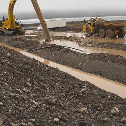
slurry wall
Slurry trench cut-off wall

The slurry trench walls create a low permeability curtain wall surrounding the excavation and it is a permanent water exclusion system. Slurry trench walls are can be quickly installed and relatively cheap, but the cost increases rapidly with depth. It is very applicable in silts, sands, and gravel up to a permeability of about 5 x 10⁻³ m/sec.

Structural Concrete Diaphragm wall

Diaphragm walls can be used as cut-off walls for dams or excavation pits, as foundations, or as enclosures for structures. A diaphragm wall is a structural concrete wall constructed panel by panel in a deep trench excavation using either precast or in-situ concrete pours.

Diaphragm walls can serve as retaining walls, water-cut-off structures, deep foundations, basement walls, or as separating structures for underground facilities. They are constructed as ground-level concrete or concrete reinforced with steel walls. They are thought to be almost water-impermeable and deformation-resistant.

image 6
Diaphragm wall in shaft construction

Diaphragm walls are permanent structures that support the sides of the excavation and often form the sidewalls of the finished construction. They can be keyed into rock and have the advantage of minimum noise and vibration. However, high cost may make the method uneconomical unless walls can be incorporated into a permanent structure.

It is applicable in side walls and shafts in most soils and weak rocks but the presence of boulders may cause problems.

Secant (interlocking)and contiguous bored piles

A retaining wall made of closely spaced bored piles can be used to construct a deep basement or a cut-and-cover tunnel. The piles could be constructed so that they almost touch each other (contiguous). A watertight retaining wall can be created by grouting the spaces between the piles.
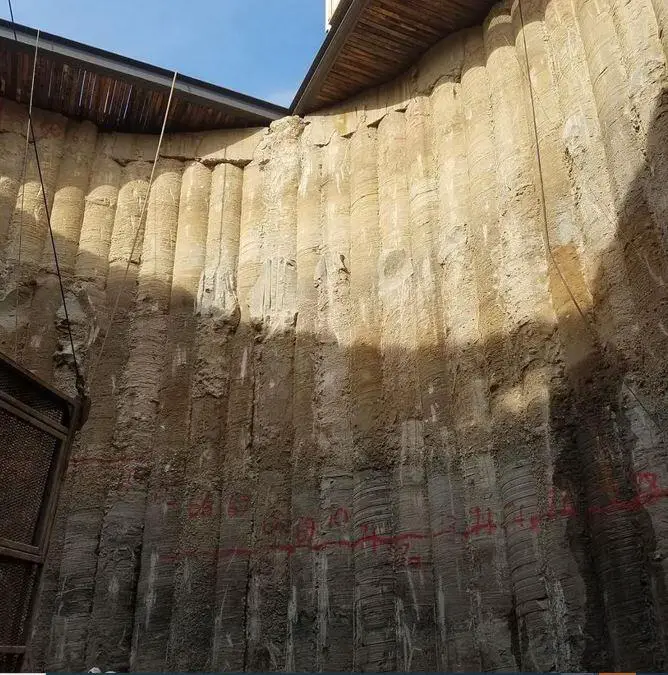
secant piles
Secant piles

This method of construction results in a more effective form of structure when the piles interlock. The piles will typically need propping during soil excavation before the permanent floor and/or roof structure is finished.

Jet Grouting

In jet grouting, a stabilizing fluid is injected into the subsoil (or the soil being treated) under high pressure and high velocity. The high-velocity fluid jets are used to create different geometries of cemented soil in the ground and typically form a series of overlapping columns of soil/grout mixture that can prevent the movement of groundwater.

Jet grouting can be messy and create large volumes of slurry. There is a risk of ground heave if not carried out with care. Jet grouting is Relatively expensive and applicable for open excavations in most soils and very weak rocks.

Deep soil mixing columns

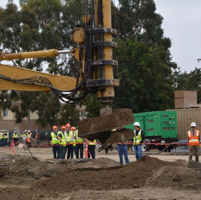
In this permanent water exclusion solution, overlapping columns are formed by in-situ mixing of soil and injected grout/cement using auger-based equipment. Soil mixing can be categorised into deep soil mixing and shallow soil missing. The mixture of binding agent and natural soil produces columns with very low permeability. This approach produces little spoil, and it is less flexible than jet grouting. It is relatively expensive.
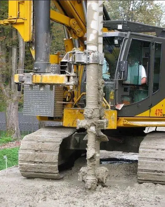
deep soil mixing equipment

Injection grouting using cementitious grout

Injection grouting is a process by which grouts are injected under pressure into open fissures, voids, cracks, and pores in a soil/rock mass. The grout fills the pore spaces, preventing the flow of water through the soil.
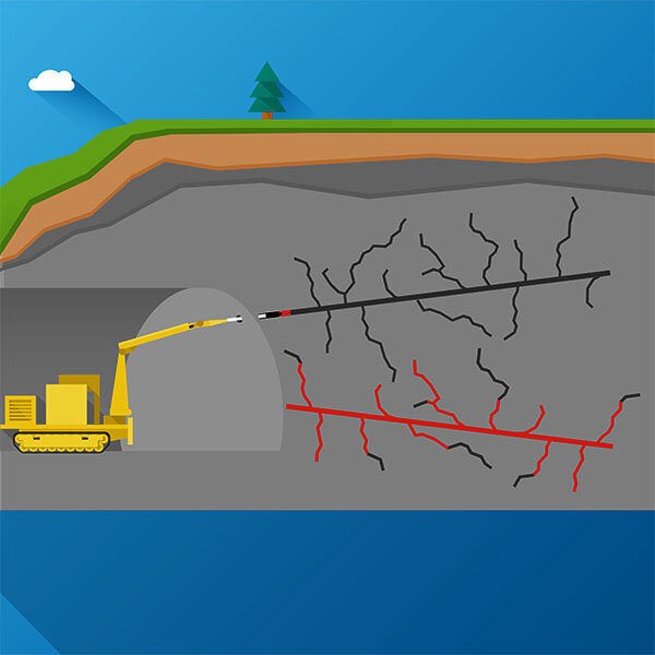
injection grouting in a tunnel
Injection grouting in a tunnel

Equipment is simple and can be used in confined spaces. A comparatively thick zone needs to be treated to ensure a continuous barrier is formed. Multiple stages of treatment may be needed. The procedure is applicable to tunnels and shafts in gravels and coarse sands, and fissured rocks.

Artificial ground freezing

Ground freezing is a temporary water exclusion solution during construction. In this solution, a ‘wall’ of frozen ground (a freeze wall) is formed using brine or liquid nitrogen, which can support the side of the excavation as well as exclude groundwater.
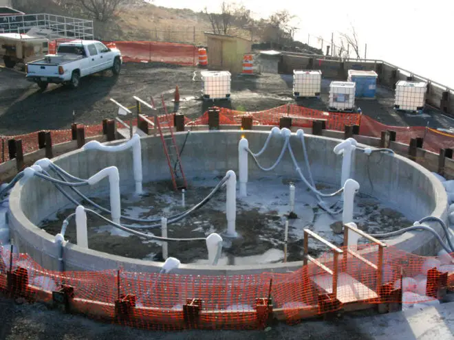
ground freezing in construction
Ground freezing in construction

This approach may not work if groundwater flow velocities are excessive (> 2 m/day for brine or 20 m/day for liquid nitrogen). Liquid nitrogen is expensive but quick; brine is cheaper but slower. Liquid nitrogen is to be preferred if groundwater velocities are relatively high. Plant costs are relatively high.

Compressed air

In this temporary groundwater control solution, increased air pressure (up to 3.5 bar) raises pore water pressure in the soil around the chamber, reducing the hydraulic gradient and limiting groundwater inflow. Potential health hazards to workers. Air losses may be significant in high-permeability soils. High running and set-up costs.

It is suitable for confined chambers such as tunnels, sealed shafts and caissons.

Design of Light Gauge Steel Columns | Cold-formed Steel Columns

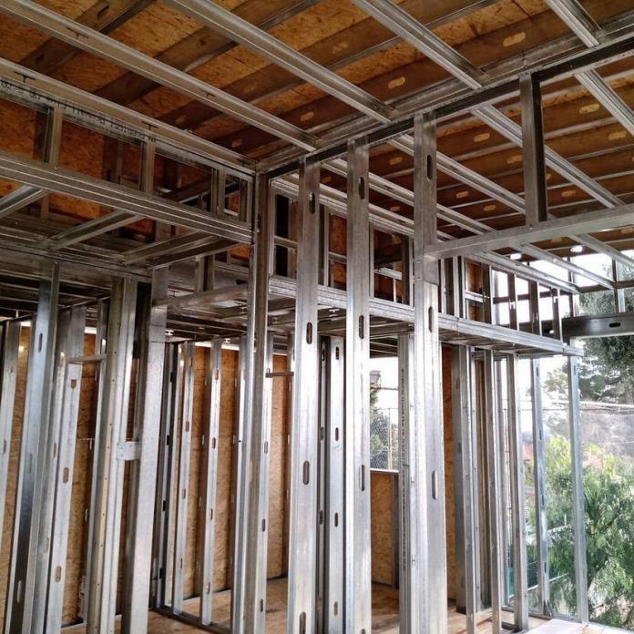
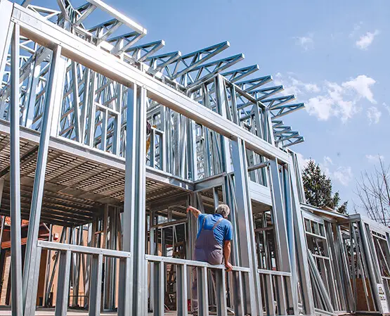
Axial compression loads from light gauge framed buildings must frequently be carried by light gauge steel members (cold-formed sections), such as the studs in a load-bearing wall. Similar to their hot-rolled counterparts, light gauge steel compression members’ failure is likely to be caused by buckling rather than cross-sectional yielding, yielding a member resistance that is much lower than the squash load of the section.

Since its buckling resistance must be calculated, the design process for such a member is in many ways comparable to that of hot-rolled steel columns. However, there are a number of ways in which the behaviour of light steel wall studs differs from that of hot-rolled columns, and these variations must be taken into account during the design process.

Contrary to columns, which function as separate parts inside a structural frame, load-bearing panels are created using light steel wall studs, plasterboard, and often some type of sheathing board. A certain amount of lateral constraint in the minor axis of the studs will be provided by the presence of the boards, which can be used to determine the buckling resistance. Any constraint must, however, be tested using studs of a representative slenderness range and a build-up of boards that is comparable to that used in actual practice.

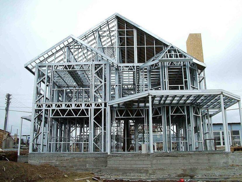
light gauge framed building
Light gauge framed building

While hot-rolled steel columns typically behave according to flexural buckling, many light steel sections can also buckle in a torsional-flexural manner. This form of failure will naturally control the member’s resistance if torsional-flexural buckling occurs at a lower magnitude of load than flexural buckling.

The elastic critical buckling load utilized for design is assumed to be the least significant of the elastic critical buckling loads for flexural buckling, torsional buckling, and torsional-flexural buckling. This is reflected in the Eurocode design guidelines.

Last but not least, light steel sections are prone to local and distortional buckling, both of which can negatively affect a member’s ability to withstand compression. When estimating the compression resistance, this should be taken into account by utilizing the effective cross-sectional area rather than the area of the gross cross-section.

Design Procedure According to the Eurocodes

Clause 6.2 of BS EN 1993-1-3 outlines the design processes for compression members made of light gauge steel. But because the design of hot-rolled columns is comparable, designers are directed to Clauses 6.3 of BS EN 1993-1-1 for the majority of the details, including the buckling curves.

When a light gauge steel member is subjected to axial compression, the design buckling resistance is given by:

Nb,Rd = χAefffyM1

Where;
χ is the reduction factor for flexural buckling
Aeff is the area of the effective cross-section
fy is the yield strength of the steel
γM1 is the partial factor of safety for buckling

The reduction factor χ is used to quantify the reduction in resistance below the squash load of the section due to buckling. It may be obtained from BS EN 1993-1-1 using the appropriate buckling curve and the value of slenderness λ corresponding to the critical mode of failure.

BS EN 1993-1-1 offers a choice of 5 buckling curves, but this is restricted to 3 curves for light gauge steel according to Clause 6.2.2 of BS EN 1993-1-3. The appropriate choice of curve for various types of cross-section is given in Table 6.3 of BS EN 1993-1-3.

The slenderness λ is given by:

λ = √(Aefffy/Ncr)

Ncr is the elastic critical buckling load, which for flexural buckling is equal to the Euler load and is given by:

Ncr = π2EI/Lcr2

where:
E is Young’s modulus for the material.
I is the appropriate second moment of area (for the gross cross-section).
Lcr is the effective length between points of restraint.

The reduction factor χ may be obtained directly from the buckling curves printed in BS EN 1993-1-1 or from the following equations:

Φ = 0.5 [1 + α(λ – 0.2) + λ2]
χ = 1/[Φ + √(Φ2 – λ2)]

α is the imperfection factor corresponding to the chosen buckling curve. Values of α are given in Table 6.1 of BS EN 1993-1-1.

LIGHT GAUGE FRAMING

Design Example of Light Gauge Steel Columns

A light gauge steel building is to be constructed using cold-formed sections. Determine the buckling strength of a steel column in the wall stud constructed using a lipped channel section (200 x 65 x 2) which is restrained at the top at 3.5 m in the y-direction, and at 1.75m in the z-direction.

Length of member between restraints:
Ly = 3.50 m
Lz = 1.75 m

Effective lengths (assuming that the member is pin-ended):
Ly,cr = 3.00m
Lz,cr = 1.50m

Section depth h = 200 mm
Flange width b = 65 mm
Stiffener depth c =25 mm
Corner radius r =3 mm
Nominal thickness tnom = 2 mm
Core thickness t = 1.96 mm
Design strength fy = 350 N/mm2
Young’s modulus E = 210000 N/mm2
Partial safety factor γM1 = 1.00

Gross section properties
Area of gross cross-section A = 729 mm2
Second moment of area (major axis) Iy = 440.5 cm4
Second moment of area (minor axis) Iz = 44.26 cm4

Effective section properties
The effective area of the cross-section in compression: Aeff = 459.1 mm2 (This effective area has already been calculated by Heywood and Way, 2012).

Along the major axis;
Lcr,y = 3.5 m
Ncr = π2EI/Lcr2
Ncr = (π2 × 210000 × 4405000)/35002 = 745296.1266 N
λ = √(Aefffy/Ncr) = √(459.1 × 350)/745296.1266 = 0.464

Along the minor axis;
Lcr,z = 1.75 m
Ncr = π2EI/Lcr2
Ncr = (π2 × 210000 × 442600)/17502 = 299539.6737 N
λ = √(Aefffy/Ncr) = √(459.1 × 350)/299539.6737 = 0.732

The buckling curve b is appropriate for the y-y and z-z axis. The imperfection factor for buckling curve b, α = 0.34

Φ = 0.5 [1 + α(λ – 0.2) + λ2]

Φy = 0.5 [1 + 0.34 (0.464 – 0.2) + 0.4642] = 0.652
Φz = 0.5 [1 + 0.34 (0.732 – 0.2) + 0.7322] = 0.858

X = 1/(Φ + √(Φ2 – λ2))
Xy = 1/[0.652 + √(0.6522 – 0.4642)] = 0.900
Xz = 1/[0.858 + √(0.8582 – 0.7322)] = 0.765

Therefore;
Nb,Rd,y = (Xy Aeff.fy)/γm1 = (0.9 × 459.1 × 350) / (1.0) = 144616.5 N = 144.616 kN
Nb,Rd,= (Xz Aeff.fy)/γm1 = (0.765 × 459.1 × 350) / (1.0) = 122924 N = 122.92 kN

In this case, the lesser holds for the flexural buckling resistance.

Hence Nb,Rd = 122.92 kN

Article reference:
Heywood M. and Way A. (2012): Design of light gauge steel elements. In Steel Designer’s Manual (Davison B. and Owens G. W. eds). Wiley-Blackwell,UK

Plate Girders

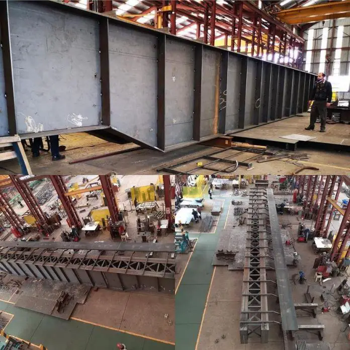
Plate girders are built-up beam sections manufactured to support massive vertical loads over long spans with consequent bending moments that are greater than the moment resistance of readily accessible rolled sections. The plate girder is a built-up beam that is made up of two flange plates that are fillet welded to a web plate to create an I-section (see Figure 1).

The primary function of the top and bottom flange of plate girders is to withstand the axial compressive and tensile forces induced by the applied bending moments, while the primary function of the web is to withstand shear. In fact, some codes of practice employ this division of structural action as the basis for design.

image 3
Figure 1: Elevation and cross-section of a typical plate girder

By extending the distance between them, the required flange areas for a given bending moment can be decreased in a plate girder. Therefore, it is advantageous to increase the distance between flanges for an economical design. The web thickness should be decreased as the depth increases to minimize the girder’s self-weight, however, this makes plate girders more susceptible to web buckling issues than rolled beam sections.

Plate girders are frequently employed in small- to medium-span bridges and occasionally utilized in buildings as transfer beams. Design guidelines are in BS EN 1993-1-5 (2006). This article describes current plate girder design procedures and includes references to the pertinent code provisions.

plate girder bridge
Figure 2: Old plate girder bridge

Advantages and Disadvantages of Plate Girders

Plate girder fabrication prices have decreased significantly as a result of the advent of highly automated workshops, but box girder and truss fabrication costs are still high because these structures must still be made largely by hand.

When compared to rolled sections, fabricated plate girders can make better use of the material since the designer has more ability to alter the section to account for variations in the applied forces. As a result, plate girders with variable depth have become more prevalent in recent years.

Compared to trusses, plate girders are more aesthetically beautiful and easier to transport and build than box girders.

The use of plate girders has some limitations. They are heavier, more difficult to transport and have higher wind resistance than trusses. It is also more challenging to provide openings for building services. Because compression flange stability is an issue, plate girder erection can occasionally present challenges.

Selection of cross-section for plate girders

During the preliminary design of plate girders, some factors can be considered for the initial selection of the dimensions. They are described as follows;

Span-to-depth ratios

Modern fabrication techniques enable the cost-effective production of plate girders with constant or variable depth. Constant-depth girders have historically been more prevalent in buildings, but as designers show a greater willingness to alter the steel structure to accommodate services, this could change. Table 1 lists suggested ratios of span to depth for plate girders in buildings.

ApplicationsSpan-to-depth ratio
(1) Constant-depth beams used in simply-supported composite girders, 12 to 20 and for simply-supported non-composite girders with concrete decking12 – 20
(2) Constant-depth beams used in continuous non-composite girders using concrete decking (N.B. continuous composite girders are uncommon in buildings)15 – 20
(3) Simply-supported crane girders (non-composite construction is usual)10 – 15
Table 18.1: Recommended span-to-depth ratios for plate girders used in buildings

Recommended plate thickness and proportions

Although more slender cross-sections are permissible, in general, the slenderness of plate girders used in buildings should not exceed the restrictions established for Class 3 cross-sections (given in Clause 5.5 of BS EN 1993-1-1). The choice of plate thickness and cross-sectional buckling are connected. In order to restore proper stiffness and strength, if the plates are too thin, stiffening may be necessary; however, this additional labour is expensive.

In view of the above, the maximum depth-to-thickness ratio of the webs (cw/tw) of plate girders in buildings is usually limited to:

cw/tw < 124ε = 124(235/fyw)0.5

where fyw is the yield strength of the web plate.

The outstand width-to-thickness ratio of the compression flange (cf/tf) is typically limited to;

cf/tf < 14ε = 14(235/fyf)0.5

where fyf is the yield strength of the compression flange. Note that cw and cf are the flat element widths, measured from the edges of the fillet welds (or root radii for rolled sections).

For initial design purposes, when the weld size may be unknown, it is conservative to ignore the weld and take cw = hw (the distance between the flanges) for webs and cf = b/2 – tw/2 for outstand flanges. Changes in flange size along the girder are not usually worthwhile in buildings.

For non-composite girders the flange width is usually within the range 0.3 – 0.5 times the depth of the section (0.4 is most common). For simply-supported composite girders these guidelines can still be employed for preliminary sizing of compression flanges. The width of tension flanges can be increased by 30%.

Stiffeners

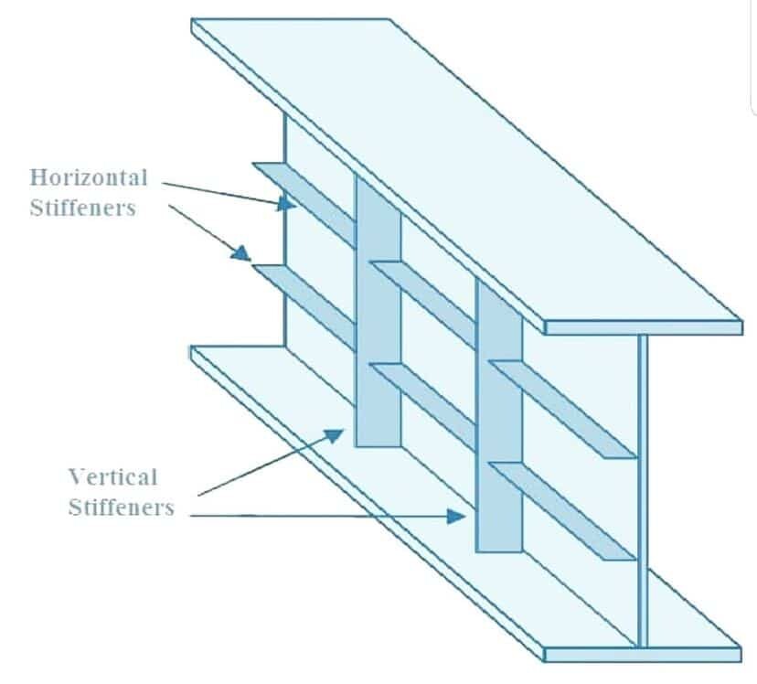
Plate girders used in structures don’t typically require longitudinal web stiffeners. When the resistance of the unstiffened web would otherwise be surpassed, transverse (vertical) web stiffeners may be used to increase the resistance to shear close to the supports or to carry highly concentrated transverse forces acting on the flanges. Because there is less shear in these areas, the necessity for intermediate stiffening reduces.

stiffener in plate girder
Figure 3: Stiffeners in plate girders

The use of intermediate transverse web stiffeners improves the web panels’ ultimate shear buckling strength τu (including post-buckling or post-critical), as well as elastic shear buckling strength τcr. A decrease in the web panel aspect ratio a/hw (width/depth) greatly enhances the elastic shear buckling strength.

Enhancing tension field action causes the boundary members to resist diagonal tensile membrane stresses that develop during the post-buckling phase, increasing the ultimate shear buckling strength (transverse stiffeners and flanges).

Since there is little gain in strength for smaller panel aspect ratios, intermediate transverse stiffeners are often positioned such that the web panel aspect ratio is between 1.0 and 2.0. In order to create what is known as a rigid end post, pairs of stiffeners are occasionally used at the end supports. Generally speaking, the girder’s overhang beyond the support is limited to no more than one-eighth of its depth.

Effects of Soil Structure, Water Content, and Density on the Expansion Potential of Soils

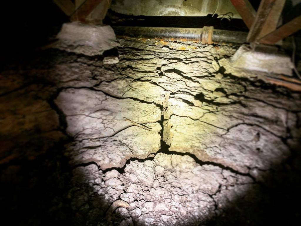
The level of risk associated with foundation or slab movement at a site is determined by the expansion potential of soil or sedimentary bedrock formation. Any soil or rock element that has the ability to expand in volume with increasing water content is often referred to as expansive soil.

The volume of soil decreases as a result of consolidation, which is a process that forces water out of the pores and fills them with soil particles. However, during swelling, water is absorbed into the soil, which is the reverse of consolidation, in that it forces the soil’s particles apart and causes an increase in volume. This swelling may result in issues very similar to differential settlement by lowering the soil’s ultimate bearing capacity and shear strength.

IMG 2094
Figure 1: Expansive soils can cause problems to structures and foundations

Swell and swelling pressure can result from elastic restitution after a load is removed, from water adhering to the surface of soil particles, or from the particles expanding as a result of the adsorption of water into the soil particles. Of these, the adsorption of water is the most common. To comprehend the phenomenon of adsorption, a basic understanding of clay mineralogy is required.

The soil structure, dry density of the soil, the initial moisture content, and the availability and characteristics of water are all factors that affect swelling properties in addition to soil composition.

Effect of Soil Structure on Expansion Potential of Soil

The way soil particles interact will depend on their orientation within the soil mass and their distance from one another. The particles may obtain different degrees of orientation depending on the circumstances present during the deposition.

The particle orientation for flocculated and dispersed soil structures is shown in Figure 2. The figure exemplifies the extremes of totally flocculated and fully dispersed soil structures. Particle orientation in most soils would fall between these two extremes. It is convenient to think about the structures that are exhibited while considering the effects of density and soil structure on expansion potential.

image
Figure 2: Sediment structures: (a) flocculated orientation; (b) dispersed orientation

It is obvious that the interactions between micelles in a flocculated structure, such as the one in Figure 2a, are principally driven by the contacts between the ends of the particles and the faces of adjacent ones. In contrast to the dispersed structure, the flocculated structure has a greater gap between particles.

It follows that in contrast to the dispersed structure shown in Figure 2b, crystalline and osmotic swelling would be less effective in the flocculated structure. The soil structure would lean more toward the dispersed structure for highly overconsolidated clays that have been subjected to substantial overburden stresses.

Effects of Water Content on Expansion Potential

Swelling won’t occur until there is free water available. Studies have revealed that depending on the type of ions in the water and whether or not there are ions already adsorbed on the soil particles, the electrolyte concentration of the water may change the swelling characteristics. The soil’s expansive properties could be significantly changed if the ions in the water have the capacity to replace the ions that have been adsorbed there.

The expansion potential will also be influenced by the distance between particles, the hydration states of the cations, and particle orientation. As a result, it would be expected that soil with a high dry density and low initial water content would have a higher expansion potential than soil with a lower dry density and a higher initial water content.

Chen (1973 and 1988) conducted oedometer experiments on samples that had been compacted to the same initial density but with different initial water contents. The results of the findings are shown in Figure 3. It is obvious that the initial water content significantly influenced the percentage swell.

Effect of initial water content on expansion potential of soils
Figure 3: Effect of initial water content on volume change

Chen (1973 and 1988) also performed oedometer tests on samples with different dry densities and the same initial water content. Figure 4 shows these findings for percentage swelling and swelling pressure. They demonstrate quite clearly that both the percentage swelling and the swelling pressure were significantly influenced by the initial density. As a result, the expansion potential of the soil increases with initial soil moisture content and soil density.

Effect of dry density on expansion potential of soils
Figure 4: Effect of dry density on volume change and swelling pressure

Effects of Dry Density on Expansion Potential

The expansion potential for a remoulded soil sample increases with the density to which the sample is compacted. Similar to this, the swell potential decreases as water content increases.

Dry density is one of these parameters that is crucial. This is explained by taking into account how many soil particles there are in a given volume. The surface area accessible for the adsorption of water will increase with the number of particles in a unit volume, increasing the potential for swelling.

It was observed during laboratory studies that when the degree of compaction increases, swelling in the presence of water at a certain confining pressure increases. This can be attributed to the fact that more clay particles would occupy the same volume due to the greater compaction.

Studies with compacted clays have shown that soils compacted on the dry side of the optimum moisture content are likely to have a flocculated structure, whereas soils compacted on the wet side of optimum moisture content tend to have a dispersed structure, suggesting that expansion potential may be attributable to soil structure. Although soil structure may contribute to the mechanisms causing swelling, it’s possible that the initial moisture content at which the soil is compacted is more significant.

The capacity of the soil to absorb water is closely correlated with swelling potentials. It is clear that swell potential depends on the initial moisture content because the mass can only absorb a given amount of water. Compared to samples of the same density compacted wet of optimum, samples compacted dry of optimum exhibit higher swelling characteristics and swell to larger water contents.

Who is a Geotechnical Engineer?

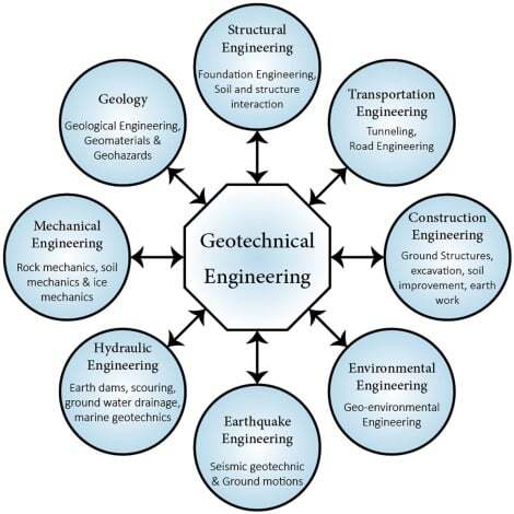
Geotechnical engineering is a branch of civil engineering concerned with the engineering behaviour of soils. Geotechnical engineers apply the principles of soil and rock mechanics to the design of the foundation of all structures and infrastructures resting on the ground, and the use of geomaterials (soils and rocks) for construction. They are also interested in ground improvement, and protection of the soil and groundwater from pollution. Geotechnical engineering is also known as soil engineering.

Geotechnical engineers, therefore, design the foundations of buildings, bridges, dams, embankments, highways, earthworks and deep excavations,  natural and man-made earth slopes, landfills, retaining walls, tunnels, cofferdams, etc. In practice, they work closely with structural engineers, highway/transportation engineers, geologists, water resources engineers, etc.

geotechnical engineering

Soil is a product of nature with so many different properties. Some soils are firm and stiff enough for construction purposes, while some soils are weak and marginal, hence unsuitable for construction purposes.  

The loads from all structures are ultimately transferred to the ground, and it is expected that the ground should be able to withstand the load without undergoing excessive settlement or shear failure. Furthermore, when geomaterials are to be used in civil engineering constructions such as highways, embankments, earth dams, etc, the material selected should have specific engineering properties that will prevent premature failure of the construction. It is the job of geotechnical engineers to recommend suitable materials or design the stabilisation/modification of existing materials.

During the design of foundations, the size and type of foundation can be altered to ensure that the pressure on the soil is within allowable limits. This is essentially the job of geotechnical engineers.

geotechnical engineering construction
Geotechnical engineering construction

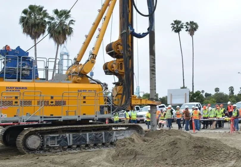
In some cases, the load coming from the structure may be too high, or the soil near the surface may be too weak, such that the geotechnical engineer may recommend a deep foundation such as piles. Using the geotechnical soil investigation report, geotechnical engineers recommend the depth, size, type, and allowable load on the pile. 

In essence, geotechnical engineers perform geotechnical analysis to assess site condition, perform field and environmental investigations, plan and conduct geotechncial exploration, review construction design proposls and approve geotechnical aspects.

A lot of theories are applied during the design of foundations and other earthen structures, and a geotechnical engineer combines them with soil investigation findings to decide on the most suitable foundation. 

Some important topics of geotechnical engineering are;

(1) Shear strength of soils
(2) Compressibility and consolidation
(3) Stresses in soil
(4) Phase relationship and physical properties of soils 
(5) Compaction
(6) Characterisation/Classification of soils

These topics form the basis of many geotechnical engineering design concepts such as foundation design, retaining walls design, stability of slopes, dam engineering, highway construction etc. Other important topics in geotechnical engineering are the flow of water through soils (hydraulic conductivity), soil dynamics, ground improvement, etc.

Geotechnical engineers are also interested in the improvement of marginal soils such as expansive soils, collapsible soils, etc in order to improve their engineering properties. 

Depending on the findings of the geotechnical soil investigation report, overexcavation and replacement of the weak soil with a more suitable material may be recommended. Other solutions can include, stabilisation of the soil with cement, lime, pozzolans, agricultural and industrial wastes, etc. Fibres and geotextiles are also used in soil stabilisation and improvement.

Other methods such as the use of vertical sand drains, deep soil mixing, stone columns, dynamic compaction, micro piles, and grouting can be used to densify weak soils and reduce settlement potential. 

Therefore, the practice of geotechnical engineering relies heavily on soil investigations which usually include laboratory and field testing of soil and rock samples. The results obtained from laboratory investigations are then used to carry out design with an appropriate factor of safety.

Geotechnical engineers are found in private consultancy, in academia, as borehole experts, construction industry, the oil and gas industry, the mining industry, military and warfare, water resources companies, etc. Their services can include; foundation design, design of earthen structures, groundwater extraction consultancy, verification of designs, design of machine foundations, structural design of highway pavements and embankments, ground improvement, etc.

Geotechnical engineers usually have civil engineering as their first degree, and may go ahead to obtain post graduate degrees in geotechnical engineering. They must also be registered/licensed to practice engineering in their country or state. This involves passing all the professional exams and interviews involved in the qualification process.

Some of the aspects of geotechnical engineering that are distinguished as a result of research and practice are as follows:

  • Transportation geotechnics
  • Geo-environmental engineering 
  • Energy geotechnics
  • Rock mechanics
  • Soil mechanics
  • Foundation Engineering 
  • Marine/offshore geotechnics

Professional Bodies in Geotechnical Engineering

Some notable geotechnical engineering professional bodies are;

Who is a Structural Engineer?

Structural engineering is a field of civil engineering that is concerned with the analysis and design of structures and infrastructures such as buildings, bridges, retaining walls, water-retaining structures, towers, masts, etc. By implication, structural engineers are responsible for the design of structures and infrastructures that serve the benefit of mankind.

A structural engineer uses the principles of mathematics and applied physics to develop solutions that will guarantee the safety and stability of structures in the most economical way. A structure is commonly defined as a system of connected parts designed to resist loads.

In buildings, while an architect is concerned with aesthetics and optimal arrangement of spaces and fenestrations, a structural engineer is concerned with the safety, stability, and integrity of the building. In other words, his commitment is to ensure that the building will safely withstand all loads without collapsing in part or in whole.

work of structural engineering
The stability of tall buildings is a work of structural engineering

The expertise and skills of a structural engineer require that they should be able to provide leadership, innovation, supervision, and adequate technical skills that will ensure that their designs are built according to their details and specifications. A professional structural engineer should be in touch with the real world, and be current with the latest industry innovations in materials, codes of practice, requirements, and government policies and legislations.

Where do structural engineers work?

Structural engineers are found in diverse fields of endeavour such as in academia as tutors and researchers, independent practitioners (self-employed consultants), construction companies, consultancy firms, government agencies and ministries, oil and gas industries, maritime and logistics, etc. Their roles are often interwoven between design and supervision. They also represent the interests of their employers by checking or reviewing the designs done by other engineers, before granting approval.

image 61
Structural engineers in an office

During the design and construction of buildings and other municipal infrastructures, a structural engineer works closely with architects, town planners, geotechnical engineers, surveyors, and MEP engineers.

Becoming a structural engineer

In the modern world, it is impossible to become a structural engineer by trade. The art and science of structural engineering are fairly technical in that it requires a dedicated university degree, and adequate professional training before someone can be considered a structural engineer. 

Most structural engineers have civil engineering as their first degree, and most of them go ahead to obtain a Master’s degree or PhD in structural engineering. However, in some countries or universities, it is possible to study structural engineering as a first-degree course.  It is important to note that having a first degree in engineering does not make one a professional engineer, but a registrable engineer. Graduate engineers are often required to practice for about four years before applying to become professional engineers.

To become professional, it is expected that an engineering graduate registers, and passes all professional exams and interviews in order to be recognised as a professional. Some of the professional bodies for civil engineers are the Institution of Civil Engineers (ICE), the Institution of Structural Engineers (IStructE), etc. The person is also expected to fulfil the requirements of the state or country where they practice engineering in order to be licenced. 

Typical Structural Engineering Courses

Some of the core courses that make up structural engineering in universities are:

  • Engineering Mathematics
  • Engineering Mechanics: Statics
  • Engineering Mechanics: Dynamics
  • Strength of Materials
  • Theory of structures (Structural Analysis)
  • Design of reinforced concrete structures
  • Design of steel structures
  • Design of timber structures
  • Structural detailing
  • Matrix analysis of structures 
  • Civil Engineering Materials
  • Dynamics of structures
  • Foundation/Soil Engineering 

These courses are usually adequate for the technical knowledge required of a structural engineer at the undergraduate level. 

At the post-graduate level, the following courses are usually treated in deeper detail, even though they are introduced at the undergraduate level:

  • Advanced Design of Structures
  • Advanced Structural Analysis
  • Bridge design
  • Theory of plates and shells
  • Stability of structures
  • Computational/Variational Structural mechanics
  • Dynamics of structures and earthquake engineering
  • Plastic and non-linear analysis of structures
  • Fire Engineering 
  • Sustainable design etc

However, the type and number of courses offered at the postgraduate level vary from institution to institution. Sometimes, the courses are pushed towards the research interests of the Department.

The Practice of Structural Engineering

Armed with the knowledge from these courses and adequate field experience, a structural engineer is able to assess the loads expected to act on a structure, the effects of the load on the structure, and provide adequate members and details to withstand the load. A structure is expected to perform satisfactorily throughout its design life without undergoing excessive deflection, vibration, cracking, or final failure.

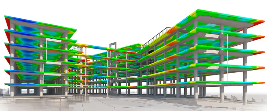
A modern structural engineer is expected to have very good computer skills, and the use of CAD software such as AUTOCAD is almost inevitable these days. Furthermore, the use of spreadsheets, structural design software, and 3D modelling software also come in handy. However, all structural engineers should be able to perform very quick checks and calculations using pen and paper.

image 60
Typical structural engineering model (Source: autodesk.com)

The communication skills (written and oral) of a structural engineer should be top-notch, with a touch of class. This is because more often than not, structural engineers write reports and evaluations. He/she should also have very good people skills and adequate knowledge of the economy and politics, as feedback and site inspections are part of the job. A structural engineer should be able to provide objective information and feedback that resonates with real-world experience.

A structural engineer is people-oriented, and the safety of the public and end-users of his/her design tops the list of priorities. At the same time, he/she tries to ensure that the solutions proposed are not unreasonably expensive. Careful attention is also paid to the beauty and harmony of the final output. 

A structural engineer is a good planner who knows that there are implications to every decision made during any design. So when next you come across a structural engineer, ask for his/her favourite drink, and get it for him/her right away.

Mechanically Stabilised Earth (MSE) Walls

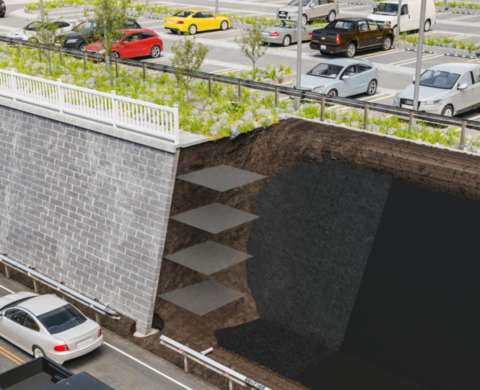
Since ancient times, people all over the world have practised the art of strengthening earthen structures with brushwood, bamboo, straw, and other materials of a similar nature. The additional strength added by such reinforcements gave birth to mechanically stabilised earth (MSE) walls and structures.

In the year 1963, a French architect and engineer named Henri Vidal was successful in obtaining a patent for a general configuration of applying the aforementioned principle to the construction of embankments. It was adopted for retaining walls, bridge abutments, dams, foundations, and several other applications on a global scale.

The following three fundamental elements make up the patented general configuration, as shown in Figure 1.

image 55
Figure 1: Basic components of mechanically stabilised earth walls (Varghese, 2012)
  1. The earthfill (often chosen granular materials passing US sieve no. 200 with less than 15%).
  2. Soil reinforcement. Currently, this takes the shape of metal strips, geotextiles, or wire grids that are attached to the facing unit and extend enough into the earth backfill. To reduce the length of the anchorage length required, special end anchorages can also be offered.
  3. The facing unit (this is usually made of metal or concrete blocks made to maintain an aesthetic appearance of the structure and prevent soil erosion).

The Mechanism of MSE Wall

The friction generated at the soil reinforcement interfaces to stop the relative motion of the soil and reinforcement is an important component of the MSE mechanism. The reinforcements provide an apparent cohesion proportionate to the density and tensile resistance of the reinforcement and limit the lateral deformation of the reinforced earth mass.

image 56
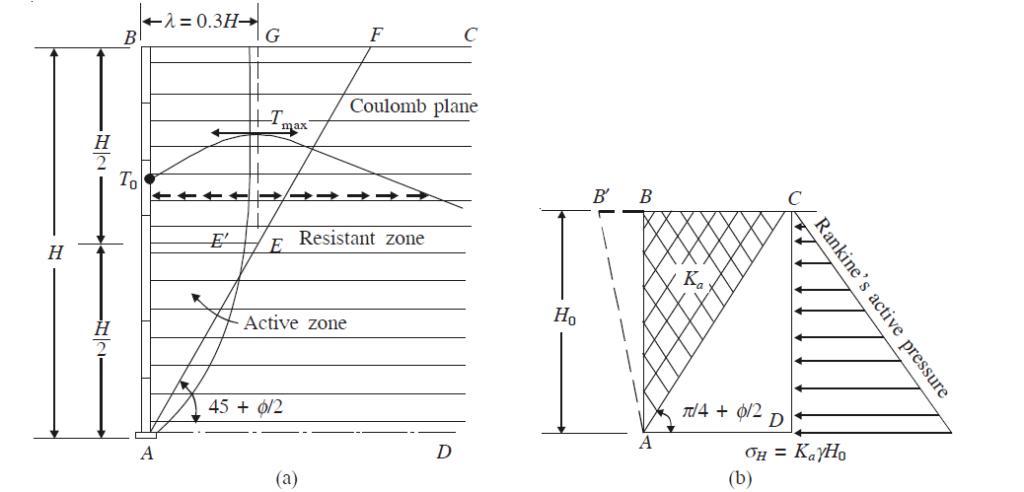
Figure 2: Design of reinforced earth walls: (a) Coulomb’s failure plane AEF and failure plane observed by tests AE¢G; (b) usual assumption for calculation of earth pressures using Rankine’s theory for conservative design (Varghese, 2012)

Depending on the type of structure and the loading conditions, the greatest tensile force in the reinforcement occurs at a distance from the mechanically stabilised earth wall. The reinforced earth is separated into the two zones shown below along this line of maximal tensile force;

  1. An active zone behind the facing where the shear forces are directed outward giving rise to an increase of tensile forces in the reinforcements.
  2. A resistant zone, where the shear stresses are mobilized to prevent the sliding of the reinforcement which is directed towards the free end of the reinforcement inside the embankment.
image 57
Figure 3: Assumed vertical pressure in soil due to concentrated loads on earth fill (Varghese, 2012)

Full-scale experiments and observations show that the behaviour of reinforced earth walls is quite different from that of classical retaining walls. The locus of the maximum tensile force in the reinforcement has been found to be different from Coulomb’s failure plane.

The remarkable features of mechanically stabilized earth (MSE) are the following:

  1. Strength – It can resist significant earth pressure and seismic force.
  2. Flexibility – They are flexible gravity structures. It adapts to substandard foundation soils and large settlements. (This is one of its main advantages over rigid walls.)
  3. Construction – It can be easily constructed by untrained labour.
  4. Low costs – Costs are low.
  5. Aesthetic factors – It has good appearance as the facing can be made of attractive designs.
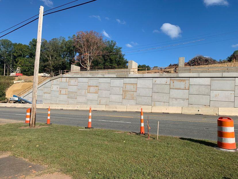
MSE Wall in construction
Figure 4: Mechanically stabilised earth wall in construction

Design of Mechanically Stabilised Earth Walls

Mechanically stabilised earth walls should be designed against the following types of failures:

  1. Tension failure of the reinforcement in the earth (internal stability)
  2. Bearing capacity failure of the base (external stability)
  3. Sliding of the whole block ABCD along the base (external stability)
  4. Overturning and tilting under the horizontal earth pressure acting on the mass.

Usually, the effect of surcharge in concentrated load is assumed to be distributed using the 2 vertical to 1 horizontal distribution as in Figure 3.

The following two types of design methods are used for determining the tension in reinforcements:

  1. The working stress method
  2. The failure plane method (limit state method).

In the working stress method, we assume the surface of maximum tension in the reinforcement based on experimental values and work out the necessary anchorage length required for the soil reinforcement. It is used as a general case to deal with all types of reinforced earth walls.

In the failure plane method, we consider the equilibrium of several wedges along a potential failure plane and estimate the tension to be developed in the steel reinforcement. We then design for maximum tension. As the working stress method is the more popular and general method, we will discuss only this method in this chapter. The conservative Coulomb’s failure surface is also assumed as the surface of failure plane.

Reinforcement Design of Mechanically Stabilised Earth Wall

The design procedure is as follows for a retaining wall without any surcharge:

Step 1: Adopt vertical and horizontal spacing of the reinforcement to be used. It may range from 0.2 to 1 m vertically and 0.7 to 1m horizontally.

Step 2: Assume the locus of maximum stress in the soil reinforcements. Different authorities have suggested different locus as shown in Fig. 26.2. The most commonly used is the conservative Coulomb’s failure plane.

Step 3: Determine the magnitude of horizontal pressure at various depths due to earth pressure as well as due to any superload on the embankment. Usually, the active earth pressure distribution is assumed and the pressure due to superload may be approximately evaluated by using 2 vertical to 1 horizontal distribution.

Step 4: Take each reinforcement strip and determine the maximum tension that will be developed in it. Let it be Ti. Thus, take the reinforcement strip at depth z from the top. The friction f developed will depend on the pressure on the strip and the coefficient of friction f = γztanδ.

If b is the width of the strip assuming that friction acts on both faces, the anchorage length La required to anchor Ti will be as follows:

La = Ti/2bf = Ti/(2bγztanδ)

where;
Ti = tension in soil reinforcement
b = breadth of the reinforcement
γz = pressure at depth z
f = friction developed between soil and reinforcement = tan δ
Ti = (γgKA) × (area of influence of reinforcing strip)

For each strip, find La, the anchorage length required to develop the corresponding anchorage.

(Note: In the field, for easiness of fabrication and installation, all the strips are made of the same length equal to the required maximum anchorage length.)

mechanically stabilised earth wall
Figure 5: Mechanically stabilised earth wall

Soil Reinforcement Selection

It is important to choose the MSE reinforcement carefully. Low-creep materials are necessary for rigid structures like retaining walls. Materials with some creep may be advantageous for embankments that may consolidate over time. Nonmetallic reinforcements are weaker than metallic reinforcements like galvanized steel and stainless steel (used to reduce corrosion).

Corrosion resistance is a benefit of plastics. Plastics come in both fabric and nonfabric forms. Fabrics are created by weaving or knitting textiles. Grids and strips make up non-fabrics; the latter is occasionally strengthened with glass fibre. In any case, these reinforcements should be chosen only after a thorough examination of their strength, creep, and durability properties. Based on the outcomes of laboratory tests provided by the manufacturer or by accredited laboratories, they should base their decision.

Reference:
Varghese P. C. (2012): Foundation Engineering. PHI Learning Private Limited, New Delhi

Design of Filters

Filters are essential for earthen constructions such as dams to be protected against seeping groundwater. A lot of literature on geotechnical engineering contains a number of empirical design criteria for filters that were created based on experimental research and prior engineering knowledge.

In the past, earth layers of various gradations or sizes were predominantly used to create filters. However, geotextile filters are increasingly widely used because of their low cost and relatively simple construction.

Filters
Figure 1: Filters in earthen structures

Applications of Filter Materials

An impermeable or permeable wall can be used to enclose the excavation in saturated soil. The pressure on an impermeable wall can be two to three times higher than on a permeable wall, on which only the effective earth pressure is acting.

On the contrary, both the earth pressure and the water pressure act on an impermeable wall. The pressures on the wall can be reduced by lowering the water level behind it, such as through pumping wells or drainage into the excavation pit. However, the in-situ soil surrounding the excavation is subjected to a hydraulic gradient as a result.

For internally unstable soils, the flow forces generated by this hydraulic gradient might result in the transport of fine soil particles into the skeleton of coarse soil particles. Unless the surface is protected with a filter and drainage material, the soil can erode at the surface where the water exits the soil body, such as at the pumped drainage well or at other drainage locations.

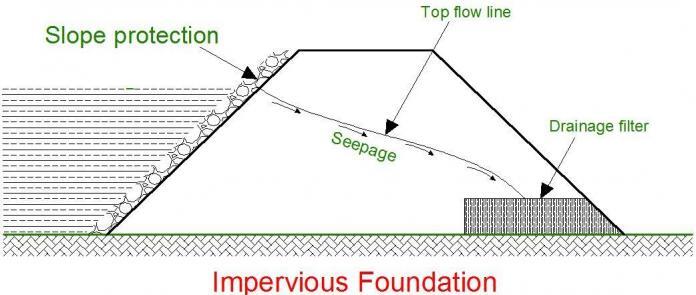
Whenever there is an impounded reservoir, a hydraulic gradient and water pressure are imparted to the soil foundation. The effective stresses and resulting soil strength are decreased by the elevated hydrostatic water pressure. The soil particles are subjected to flow forces by the imposed hydraulic gradient, which can lead to erosion at the soil body’s surface or within the soil’s skeleton, where water seeps out of the ground.

The erosion of soil particles will be stopped, and the effective stress will be raised, by adding a layer of filter material beneath a layer of drainage material at the water outlet.

image 54
Figure 2:Filters in earth dam

Because water reduces the effective stress and consequently the shear strength of the soil and applies stresses when water is moving through the soil, it has a significant impact on the stability and erosion resistance of both natural and artificial soil structures.

The stability of structures erected on or in soil is therefore improved by draining the water out of the soil structures. The soil must be drained, nevertheless, in a controlled manner. Particles within the soil skeleton or near the surface cannot be eroded by hydraulic gradients and the flow forces that result. This is ensured for natural soils by restricting the hydraulic gradient. Filter zones built into the soil structure are used to control erosion for man-made constructions.

Design of Filters

The following six factors are taken into account when designing filter materials:

(a) Filter ability
(b) Internal stability
(c) Self-healing
(d) Material segregation
(e) Drainage capacity
(f) Material durability

image 51
Figure 3: Filter and drainage criteria from Terzaghi & Peck (1948)

Filter Ability

To design soil filters, the U.S. Army Corps of Engineers (Huang, 2004) set out some criteria. These criteria are based on the particle sizes that, according to the particle size distribution curve, correspond to specific weight percentages of the protected soil and the filter material.

Clogging criterion:
To ensure that the protected soil does not clog the larger particles of the filter, the following criterion must be satisfied by the relative sizes;
D15,filter/D85,soil ≤ 5.0

Permeability criterion:
To ensure that water passes through the filter system without building up excess pressure, the following criterion is recommended;
D15,filter/D15,soil ≥ 5.0

Additional criterion:
U.S. Army Corps of Engineers also recommends the following additional criterion;
D50,filter/D50,soil ≤ 25.0

Based on the above equations, one can design a satisfactory filter system when the particle size distributions of the relevant soil samples are available.

Bertram (1940) proposed the criterion D15,filter/D85,soil ≤ 6 for soil filters based on laboratory investigations. This filter criterion was later modified to D15coarse-side,filter/D85fine-side,soil ≤ 4.

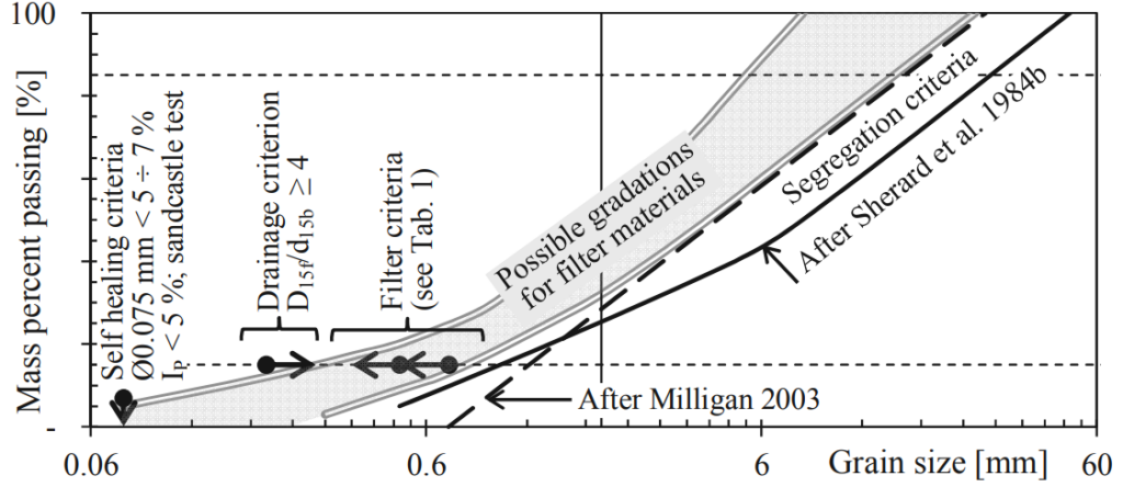
A drainage criterion of D15fine-side,filter/D85coarse-side,soil ≥ 4 was added by Terzaghi and Peck (1948)(See figure 3).

Internal Stability

When a filter material is internally stable, it prevents small soil particles from moving due to the forces of water flow. Even for water flow at high (>>1) hydraulic gradients, as happens at a fracture in the sealing zone of an embankment, all soil particles ought to stay in place. For instance, Kenney & Lau (1985) provide a useful definition of internal stability as the capacity of a granular material to avoid the loss of its own microscopic particles as a result of disturbing forces like seepage and vibration.

The filter material’s gradation curve is split into two curves at a chosen grain diameter (dS), gradation curves for the sections finer and coarser than dS, respectively, in this technique, also known as the “retention ratio criteria.” The Terzaghi filter criterion is used to compute the retention ratio (RR) for the two gradation curves: RR = D15,filter/D85,soil. This is repeated for various dS values. If all grains meet the criteria RR  ≤  7-8 rounded grains or RR  ≤ 9-10 for angular grains, they are all regarded as stable.

image 52
Figure 4: Summary of filter criteria

Self Healing

Self-healing means that when there is water flow, cracks that could develop in the filter zone owing to things like differential settlement, etc., close instead of remaining open. Therefore, cohesion cannot exist in the filter material. By limiting the amount of non-plastic (IP < 5%) fines to under 5%, this is ensured. The sand-castle test (Vaughan & Soares 1982) attests to the filter material’s compliance with the self-healing specifications.

Material Segregation

The filter zone can no longer serve its purpose of preventing fine particles from moving from the core to the filter zone or within the filter zone when the filter material segregates, meaning that the coarser particles separate from the finer particles. This is because the segregated coarse-grained components do not form a filter to the adjacent materials. Therefore, it is necessary to prevent the segregation of filter elements. Most experts concur that a high sand content and a small maximum grain size lessen segregation.

Drainage capacity

The Terzaghi criterion D15,filter/D85,Soil ≥ 4 still applies and Sherard recommends D15,filter ≥ 0.2 mm.

Material Durability

Standard tests like the Los Angeles abrasion test (ASTM C535) or the wet and dry strength variation (typical limit 35%) are frequently used to examine the durability of filter materials. For significant dam structures, mineralogical and chemical analysis of the dam material is suggested This can show whether the substance contains inclusions of (i) swellable clay minerals or (ii) water-soluble minerals, such as gypsum or carbonate rocks.

In addition to dissolving, more recent materials can also re-cement at particle interactions and produce real cohesiveness. Dam filter materials containing carbonate and sulfide should be handled carefully.

Conclusion

The stability and erosion resistance of both natural and artificial soil structures are significantly influenced by water. The stability of the soil structure is increased by draining the water out of it. The soil must be drained, nevertheless, in a controlled manner to prevent erosion. Filter materials positioned inside or on top of the soil structures are used to achieve this.

Filter materials must possess specific properties that are detailed by filter criteria, which has undergone significant progress in recent decades. These filter criteria currently consist of six distinct sections, and each of these criteria has been discussed in this article.

Conceptual Design of Earthquake-Resistant RC Buildings

The rational conceptual design of earthquake-resistant RC buildings involves the design of a structural system in such a way that the lateral seismic actions (inertia forces) are transferred to the ground without excessive rotations of the building and in a ductile manner is one of the fundamental factors influencing the proper seismic behaviour of a building.

The requirements of the design code alone cannot do this. As a result, there are some general principles that, when followed in the planning and conceptual design of the building, can significantly improve the seismic resistance of the building.

According to Penelis and Penelis (2014), 29 of the 103 reinforced concrete buildings in Athens that were the most severely damaged or collapsed following the Parnitha earthquake (September 7th, 1999) were found to have failed mostly as a result of their inadequate configuration. This was mostly ascribed to the architect and structural engineer not working together early in the planning process, when a suitable compromise could have been struck.

Conceptual Design of Earthquake-Resistant RC Buildings

According to Penelis and Penelis (2014), the guidelines that should govern a conceptual design against seismic hazard according to EN 1998-1:2004 (Eurocode 8) are:

• Structural simplicity
• Uniformity and symmetry
• Redundancy
• Bidirectional resistance and stiffness
• Torsional resistance and stiffness
• Diaphragmatic action at storey levels
• Adequate foundation

Structural Simplicity

A core objective of the conceptual design must be the design of simple structural systems with clear load paths for transmitting gravity and seismic loads from the structural components to the foundation. It should be highlighted that the analysis and design results for a simple structural system are far more reliable than those for a sophisticated one. A plan of a few simple structural systems is shown in Figure 1.

Earthquake-Resistant RC Buildings
Figure 1: Structural systems characterised by simplicity: (a) a typical form of a frame system; (b) a typical configuration of an R/C shear wall system; (c) a dual system with an R/C core and frames (Source: Penelis and Penelis, 2014)

Regularity of structure in plan and elevation

Buildings with regular plans and elevations, without re-entrant corners and discontinuities in the vertical stresses transferred to the ground, behave well during earthquakes. Irregularities in the building plan can lead to dangerous stress concentrations for the structure. In this instance, seismic joints may be used to partition the entire building with re-entrant corners into separate seismic compact portions, if necessary (Figure 2).

For sound seismic behaviour, uniformity in height and stiffness distribution is essential. Discontinuities in deck diaphragms or construction features with re-entrant corners, or discontinuities in load transfer to the foundation with walls or columns “planted on” beams and discontinued below, are warning signals for the behavior of the building in case of a large earthquake (Figure 2).

image 45
Figure 2: Unfavourable and favourable configuration in elevation (Source: Penelis and Penelis, 2014)

A special attention should be paid to this direction so that torsionally flexible or asymmetric structures, which can lead to failures of the corner columns and the walls at the perimeter, will be avoided. This is true even though the symmetrical arrangement of stiffness elements is not always possible due to architectural constraints.

image 46
Figure 3: Distribution of mass and stiffness in elevation (Source: Penelis and Penelis, 2014)

Arrangement of Structural Walls

Reinforced concrete structural walls should span the whole space between two adjacent R/C columns if there are any voids between them. This increases the structure’s stiffness, strength, and ductility (Figure 4).

image 47
Figure 4: Layout of shear walls at the perimeter (a) acceptable arrangement, (b) improved arrangement (Source: Penelis and Penelis, 2014)

Redundancy in the structure

To create a robust monolithic structure with a high level of redundancy, all structural components, including the foundation, should be strongly connected. The building’s perimeter high-stiffness cores (staircases and shafts) might readily break from the diaphragmatic system during an earthquake, causing the structure to react in an unanticipated way.

Avoidance of short columns

Avoid using short columns below the windows that may be caused by the presence of mezzanines, stiff masonry, or R/C parapets. If such arrangements cannot be avoided, consideration should be given to how they will affect the structure’s behaviour in terms of load effects, ductility, and shear capacity (Figure 5).

image 48
Figure 5: Concentration of large shear forces on short columns at the perimeter of the building (Source: Penelis and Penelis, 2014)

Avoid using flat slabs as main structural frames

Despite being relatively attractive in terms of construction due to the low cost of formwork and the available space at story for the installation of building services ducts, flat slab systems without beams should be avoided as they are not entirely covered by EN 1998-1:2004. This does not imply that they cannot be utilized in conjunction with structural walls, cores, or frames that can withstand seismic events.

Avoid having soft storeys

Avoid having large discontinuities in the elevation of the infill system, (such as open-ground stories as shown in Figure 6). This kind of stiffness discontinuity creates a soft storey mechanism that is extremely susceptible to collapsing.

Special precautions should be taken in the analysis and detailing of the structural walls and columns in the event that this type of structure cannot be avoided, as is the case in the majority of Mediterranean countries where the General Building Code requires an open storey at the ground level (Pilotis system).

image 49
Figure 6: Pilotis building (by the right)

Diaphragm Behaviour

The system of the floors and roof of a multistorey building constitutes the basic mechanism for transfer of inertial seismic forces from the slabs of the building where the masses are distributed to the vertical structural members (columns and structural walls) and thereby to the foundation. In addition, the slab system, particularly in cast-in-place R/C buildings, guarantees that each storey deck will behave as a hard disc in plane, or a horizontal diaphragm, while being flexible in the vertical direction.

The storey diaphragms contribute to the system’s increased redundancy in this way. It is clear that using R/C buildings cast in place makes it very simple to produce this 3D structure with high redundancy. There is obviously no chance of structural failure of the diaphragms in an R/C building with a compact form in plan.

But the diaphragmatic function could fail if the structural system has high-stiffness R/C cores at the edge of its perimeter, if there are re-entrant corners in the plan, or if there are very large floor openings. For these reasons, special attention must be paid to the analysis and design of the diaphragm itself (i.e., the analysis and design of the slab as a disc in-plane under the action of the inertial forces and the shear reactions of the vertical structural members on the disc).

Bidirectional stiffness and resistance

Since seismic action can occur in any direction, the structural elements should be arranged in an orthogonal in-plan structural pattern to ensure similar resistance, stiffness, and ductility in both main directions (bi-directional function). In this situation, the structure must be able to withstand any excitation thanks to its two orthogonal components.

Strong columns and weak beams

For capacity design purposes, structures must be made up of weak beams and strong columns, as this performs better during earthquakes. This concept ensures that plastic hinges will develop in the beams, and not the columns.

Offering a second line of defence

It is advised to add a second line of defence made up of ductile frames to the structural system in parallel with the shear walls. Therefore, it appears that the dual system (structural walls and ductile frames) is most suited to withstand seismic action. Independent of the findings of the investigation, ASCE 7-05 mandates that these frames must support 25% of the seismic actions. It should be emphasized that EN 1998-1:2004 does not prescribe such a requirement; rather, the structural system is upgraded insofar as its factory behaviour is concerned if the frames resist for more than 35% of the base shear.

Adequate foundation system

The behaviour of the building in reaction to seismic events is significantly influenced by the foundation. It should be noted that reinforced concrete is virtually always used for the foundation, regardless of the material used for the superstructure.

Article Source:
Penelis G. G. and Penelis G. G. (2014): Concrete Buildings in Seismic Regions. CRC Press Taylor & Francis Group

Point of Contraflexure in Structures

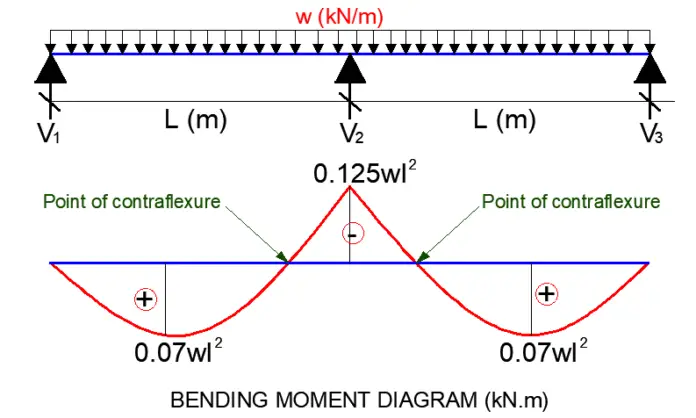
A point of contraflexure in a structure is the point where the bending moment changes signs from positive to negative (and vice versa). In other words, it is a point where the nature of the bending moment transitions from sagging to hogging. The value of the bending moment at any point of contraflexure is zero.

For a section under a sagging moment, the bottom fibre of the member is under tension, therefore, reinforcements should be provided at the bottom of the section. For a section under a hogging moment, the top fibre is in tension, and reinforcement should be provided at the top. Therefore, the point of contraflexure provides good information on how reinforcements should be arranged in reinforced concrete structures.

There is no predetermined formula for determining the exact location where the point of contraflexure will occur in a structure. The location of the point of contraflexure on a structure depends on the type of load, loading arrangement, location of supports, and types of members. The easiest way to determine the point of contraflexure in any structure is to determine the equation for the bending moment, and equate it to zero. When the x-term (distance) in the equation is solved, the point of contraflexure is readily obtained.

[themoneytizer id=”98693-1″]

Contraflexure in beams

In simply supported beams, there is no point of contraflexure since the entire beam is expected to be sagging when subjected to any lateral load. However, when an overhang is introduced to a simply supported beam, a point of contraflexure will be developed as the bending moment transitions from hogging at the cantilever area, to sagging in the span area. Once again, the loading configuration and loading locations affect how the point of contraflexure will behave.

Let us consider the simply supported beam with overhang loaded as shown below;

image 40

∑MB = 0
6VA – (15 × 62)/2 + (15 × 1.52)/2 = 0
VA = 42.1875 kN

∑MA = 0
6VB – (15 × 7.52)/2 = 0
VB = 70.3125 kN

If we cut a section x-x along the span, the bending moment equation along the span is given by;

image 42

Mx = 42.1875x – 15x2/2 = 42.1875x – 7.5x2

We can obtain the point of contraflexure by equating the above equation to zero;

Mx = 42.1875x – 7.5x2 = 0

Solving quadratically;
x = 5.625 m

Therefore, the point of contraflexure occurs at 5.625m from support A.

The maximum bending moment can be obtained by differentiating the bending moment equation (to obtain the equation for shear), and equating it to zero;

N/B: The maximum bending moment occurs at the point of zero shear.

∂Mx/∂x = 42.1875 – 15x = 0

Therefore; x = 2.8125 m
Mmax = 42.1875(2.8125) – 7.5(2.8125)2 = 59.3 kNm

Bending moment at support B;
MB = 42.1875(6) – 7.5(6)2 = -16.875 kNm

image 43

For continuous beams that are supported on pinned supports, it is expected that the hogging moments will occur at the intermediate supports, while the sagging moments will occur at the spans. Therefore, the points of contraflexure occur very close to the intermediate supports.

image 39

When a beam is fixed at one end, it is also expected that a point of contraflexure occurs close to the fixed support, as the bending moment transitions from hogging at the fixed support, to sagging in the span.

Contraflexure in frames

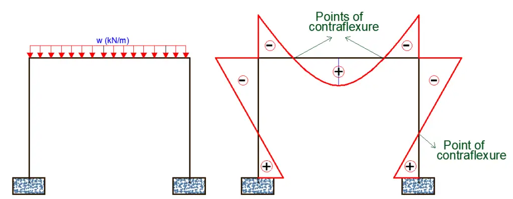
The point of contraflexure in frames is more complex than in beams. When the column of a frame is supported on a fixed support, a point of contraflexure is expected on the column. However, if the column is supported on a pinned support, there may be no point of contraflexure unless there is a lateral load on the column.

point of contraflexure in frame

On the beams of a frame, points of contraflexure are also expected because of the inherent hogging moment that exists at the beam-column junctions of rigid frames. When the bending moment transitions from hogging at the beam-column junction to sagging at the beam spans, a point of contraflexure develops.

When carrying out approximate analysis of framed structures, the point of contraflexure for columns is usually assumed to occur at the mid-point, as a known point of zero bending moment.

Significance of the point of contraflexure

Points of contraflexure are very significant in the design of steel structures and reinforced concrete structures.

Reinforced Concrete Structures

In reinforced concrete structures, the points of contraflexure provide information on where the top reinforcements should be curtailed. For instance, it is reasonable to stop the top reinforcement at the support of beams at the point of contraflexure. In the detailing guidelines of beams, this is taken as 0.25L, while in the detailing of slabs, this is taken as 0.3L, where L is the length of the span.

Furthermore, since the bending moment at the point of contraflexure is zero, it could serve as a very good point where tension bars could be lapped without any serious consequences. This however should be used with caution since the actual loading in real-life structures can vary considerably. It is advisable to follow the detailing guidelines in the code of practice.

Steel Structures

The point of contraflexure also plays an important role in the design of steel structures. For instance, in the design of portal frames, the point of contraflexure can provide the needed information for the length of the haunches, which provides increased stiffness at the column-rafter junction. It may also be desirable to locate splices and joints at the point where the bending moment is zero, so as to have more economical joints.

The point of contraflexure and the shape of the moment diagram plays an important role in the design of steel structures for lateral torsional buckling.